Vehicle Speed Warning Relay (PartTerminologyID 3792): Diagnosis, Return Prevention and Listing Guide
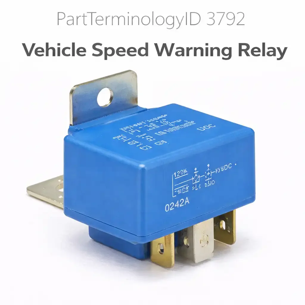
The Vehicle Speed Warning Relay, cataloged under PartTerminologyID 3792, is the combined relay and audible buzzer unit that produces an alerting sound when the driver's road speed exceeds a self-selected warning threshold. The relay is the central component of the factory speed warning option, designated RPO code U15 by General Motors, which was offered on passenger cars and personal luxury vehicles primarily during the mid-1960s through the end of the 1960s. On GM applications, the system appeared on the Corvette, Camaro, Chevelle, Impala, Caprice, Nova, Firebird, and related platforms. The relay unit is not a conventional pass-through relay that silently closes a circuit for another device; it is an electromechanical unit that both closes its contacts and produces its own audible buzzing sound through housing vibration when it is energized. The buzzing is the alert.
The Vehicle Speed Warning Relay is a restoration-era component. Production of the factory U15 system ended in the early 1970s as the emissions-era platform changes consolidated instrument clusters and eliminated many optional accessory features. The buyer population for PartTerminologyID 3792 consists almost entirely of collectors and restorers returning a factory-original vehicle to complete working condition, or enthusiasts who are correct-code matching a vehicle to its original build sheet options. New old stock units are rare and expensive. Reproduction units from specialty suppliers cover the major GM applications. The diagnostic and fitment disciplines for this PartTerminologyID are shaped by the restoration context: the speedometer head, the instrument cluster ground, and the wiring harness are more commonly the fault source than the relay unit itself, and the buyer population is experienced enough to appreciate content that addresses the whole system rather than just the relay.
What the Relay Does
System Architecture: Speedometer, Relay, and Harness
The factory speed warning system consists of three elements: a specially equipped speedometer head, the relay/buzzer unit, and a two-wire harness connecting them. The speedometer head used with the speed warning option includes a second adjustable needle, distinct from the main speed indicator needle, that the driver sets to their desired alert speed by rotating a knob or cable mechanism accessible beneath or beside the instrument cluster. This warning needle is connected to a circuit that provides a ground path when the main speed indicator needle reaches and contacts it.
The relay/buzzer unit receives ignition-switched battery voltage through one terminal, typically from a pink wire connected to an ignition-fused circuit in the fuse panel. The second terminal connects to the speedometer head's warning needle contact through a white wire. As long as the vehicle is traveling below the set warning speed, the warning needle contact is open and no circuit is completed. When the main speedometer needle reaches the set warning speed and physically contacts the warning needle, the ground path closes through the speedometer cable drive and instrument cluster chassis ground. Current flows from the fuse panel through the pink wire, through the relay/buzzer coil and contacts, through the white wire to the speedometer, and to chassis ground through the cluster. The energized relay vibrates against its mounting bracket, producing the audible buzz. The buzzing continues as long as the main needle remains in contact with the warning needle, meaning it sounds for as long as the vehicle is at or above the set speed.
The Relay as Buzzer: A Combined Function Unit
The vehicle speed warning relay is not a pure relay that silently switches another device. The relay's own vibration against its mounting surface produces the audible alert. When the coil is energized by the speedometer contact closing, the armature oscillates rapidly, creating the characteristic buzzing tone. The quality and volume of the sound depends on the relay being properly mounted to a solid surface that can conduct the vibration. A relay that is not firmly mounted, or that is mounted in a location isolated from the instrument panel structure, may produce a weak or inaudible buzz even when the electrical circuit is fully functional.
On early GM applications, the relay unit mounts on the left side of the instrument cluster or on the firewall near the steering column, with a bracket that contacts the vehicle's body structure. The mounting location is part of the system's acoustic design. A restorer who mounts a reproduction relay in a location that differs from the original bracket position may experience a working relay that buzzes inaudibly because it is not coupled to the instrument panel or firewall mass that the original mounting relied on for resonance.
Terminal Identification and Wiring
The speed warning relay unit has two active terminals and on some versions a third terminal that serves only as a mechanical alignment guide for the connector, with no electrical function. The two active terminals accept the ignition supply wire and the speedometer ground trigger wire. The physical arrangement of these terminals has varied between production runs and between reproduction units from different suppliers, and a reproduction relay that has different terminal positions than the OEM unit requires wire re-routing at the connector rather than a direct plug-in replacement.
The unit's chassis ground is typically established through the metal mounting bracket and the bracket's contact with the instrument panel or firewall metalwork. The relay does not have a dedicated ground wire on most applications; it relies on the mechanical mounting for its ground return. A relay that receives power and trigger signal but does not buzz, or buzzes only intermittently, has a high probability of a chassis ground problem at the mounting bracket rather than an internal relay failure.
Top Return Scenarios
Instrument Cluster Ground Fault Misidentified as Relay Failure
The most common cause of a non-functioning speed warning system on a vehicle where the relay is confirmed present and the wiring harness is intact is a bad instrument cluster ground. The speedometer warning contact circuit depends on a clean ground path from the speedometer needle contact, through the speedometer frame and drive mechanism, to the instrument cluster chassis ground, and from there to the vehicle's body ground. Instrument clusters on 1960s GM vehicles are notorious for developing high-resistance ground connections as the cluster mounting hardware corrodes and the cluster loses its electrical connection to the instrument panel structure.
A clean instrument cluster ground can be verified by measuring resistance between the cluster's metal housing and a known good chassis ground. Anything above approximately one ohm suggests an inadequate ground that will prevent the speed warning contact from completing the circuit even when the needles are in physical contact. Cleaning the cluster mounting screw locations, adding a dedicated ground strap from the cluster to chassis ground, and verifying continuity from the speedometer housing through the cluster ground path before ordering any relay is the correct diagnostic sequence. A buyer who replaces the relay without establishing that the cluster ground is sound may return a functional relay after cleaning the ground corrects the fault.
Speedometer Warning Contact Failure Misidentified as Relay Failure
The adjustable warning needle inside the speedometer head contacts the main speed indicator needle to complete the trigger circuit. This contact depends on the warning needle being correctly positioned, on the contact surfaces being clean enough to conduct current, and on the speedometer needle reaching the set warning speed to make physical contact. On instruments that have been sitting unused for decades, the internal contact surfaces can oxidize, the warning needle adjustment mechanism can seize, or the connection between the warning needle's electrical terminal and the wire at the back of the speedometer housing can corrode and open.
A simple bench test isolates the relay from the speedometer contact. Disconnect the white trigger wire at the speedometer. Apply ignition voltage to the relay's pink terminal and connect the relay's chassis ground to a known good ground. Then briefly connect the white trigger wire terminal directly to chassis ground, bypassing the speedometer contact entirely. If the relay buzzes when the white wire is directly grounded but does not buzz when connected to the speedometer, the fault is inside the speedometer head: either the warning needle contact surfaces are corroded, the warning needle position is not reaching the main indicator needle at any achievable speed, or the speedometer's internal ground path has failed. A buyer who performs this test determines whether to order the relay or the speedometer before placing any order.
Wire Condition Between Relay and Speedometer
The single white wire running between the relay unit and the brass terminal on the back of the speedometer head is a low-current, signal-level wire that sees no mechanical protection on most applications. After decades, this wire can develop breaks from chafing against the instrument panel structure, corrosion at the terminal where it connects to the speedometer, or poor contact at the relay terminal if the connector blades have spread or corroded. A broken wire between the relay and the speedometer produces the same symptom as a failed speedometer contact or a failed relay: no buzz at any speed.
The wire should be inspected for continuity before any component is ordered. Measuring resistance between the relay's trigger terminal and the speedometer brass terminal, with the connector disconnected from both ends, confirms wire integrity. If resistance is measurably above zero or infinite, the wire is the fault. Replacing the entire harness, if a reproduction harness is available for the application, is often more reliable than attempting to splice a decades-old original harness.
Reproduction Relay Terminal Mismatch
Reproduction speed warning relay units sold across multiple GM applications do not always have terminal positions that match every application's harness connector. The OEM relay had specific terminal positions, and aftermarket reproductions built to fit the most common applications may have the power and trigger terminals in a different positional order than the OEM unit for a specific model year or platform variant. A buyer who installs a reproduction relay and finds the buzzer sounds immediately at key-on and never stops has connected the terminals in reverse: the ignition supply is on the trigger terminal and the speedometer ground wire is on the supply terminal.
Reversing the wires at the connector corrects this problem and requires no relay replacement. However, a buyer who does not identify this as the cause may interpret the continuous buzzing as a relay fault and return the unit. Listing content that alerts buyers to verify terminal positions against their application's factory wiring diagram before connecting the relay prevents this category of return.
Weak or Inaudible Buzz From Improper Mounting
A relay that buzzes but cannot be heard from the driver's seat is not a failed relay. The buzzing is produced by the relay's physical vibration and depends on the mounting bracket being securely fastened to a surface that couples the vibration to the vehicle's interior structure. A reproduction relay installed on a makeshift bracket, or on a bracket that is only loosely attached to the instrument panel, may buzz quietly enough to be inaudible over vehicle noise.
The OEM mounting position, documented in the factory assembly instruction manual for each application, positions the relay in firm contact with the instrument panel metalwork or a firewall bracket. If a reproduced or restored relay buzzes when held in hand but cannot be heard when installed in the vehicle, the mounting bracket and its contact with the instrument panel structure should be examined before the relay is returned. Tightening the mounting hardware and verifying that the bracket makes solid metal-to-metal contact with the instrument panel typically restores audibility.
Listing Requirements
Every listing for PartTerminologyID 3792 should include:
ACES fitment data restricted to vehicle makes, models, and model years where the factory speed warning option was available as original equipment, with fitment qualified by the option code (U15 on GM applications) where possible, since not all vehicles of an applicable model year were built with the option
A clear statement that the system requires a speed-warning-equipped speedometer head in addition to the relay, and that a standard speedometer without the adjustable warning needle cannot trigger the relay regardless of relay condition
A note on the combined relay-and-buzzer function of the unit, clarifying that the relay itself produces the buzz sound rather than triggering a separate buzzer
A note on terminal position verification required for reproduction units before wiring, with a reference to the factory assembly manual for the specific application
An advisory that instrument cluster ground quality must be verified before ordering, as cluster ground faults produce no-buzz conditions identical to a failed relay
Frequently Asked Questions
My speed warning system does not buzz at all. Where should I start?
Start with the instrument cluster ground, not the relay. Apply ignition voltage to the relay's power terminal, connect the relay to a solid chassis ground, then manually ground the white trigger wire. If the relay buzzes in this bench-connected state, the relay unit is functional and the fault is in the speedometer contact, the white trigger wire, or the cluster's internal ground path. If the relay does not buzz when the white wire is manually grounded, the relay unit is the fault. This two-minute test isolates the relay from the rest of the system and determines whether ordering a relay will correct the complaint.
Does the speed warning system require a special speedometer?
Yes. A standard speedometer without the speed warning option does not have the adjustable warning needle or the internal contact that triggers the relay circuit. Substituting a standard speedometer into a vehicle equipped with the speed warning relay, or installing the relay in a vehicle that does not have the speed warning speedometer, produces a non-functional system regardless of the relay's condition. Both the relay and the speed-warning-equipped speedometer must be present for the system to operate. The speedometer is identified by the presence of a second needle with an adjustment mechanism and a brass electrical terminal on the back of the speedometer housing.
The relay buzzes constantly from the moment the ignition is turned on. What is wrong?
Constant buzzing from key-on typically means the relay is receiving a permanent ground signal on its trigger terminal rather than a switchable ground from the speedometer contact. The most likely cause is reversed terminal connections on the relay connector: the white speedometer trigger wire has been connected to the relay's power terminal and the ignition supply wire has been connected to the trigger terminal. This places the relay's coil directly across battery voltage and chassis ground at all times. Swap the two wires at the connector and verify the system behavior. If the constant buzzing persists with the wires in the correct positions, inspect the white trigger wire for a short to chassis ground at any point between the relay and the speedometer.
Can a standard automotive relay be substituted for the original speed warning relay?
Electrically, a standard relay will close its contacts when the trigger circuit is completed, but it will not produce the audible buzz that the original unit generates through its own vibration. The original speed warning relay unit is intentionally designed to oscillate and produce sound when energized. A standard relay simply closes silently. A five-terminal SPDT relay wired in a self-oscillating configuration, as has been documented in restoration community discussions, can be made to buzz through a specific wiring arrangement that causes rapid make-and-break cycling, but this is an improvised substitute rather than a direct replacement. Correct-code restorations require the original-style relay/buzzer unit.
My relay buzzes when I test it on the bench but is inaudible in the car. Is the relay defective?
No. The relay is functional if it buzzes on the bench. The audibility problem in the vehicle is a mounting issue. The relay must be firmly secured to its original bracket position with the bracket in solid metal-to-metal contact with the instrument panel structure or firewall. The relay's buzz is conducted through the mounting surface to the instrument panel, which amplifies the sound enough to be heard over vehicle noise. A relay mounted loosely, or mounted on a rubber-isolated bracket, produces an inaudible buzz even when electrically functional. Inspect and tighten the bracket mounting hardware and verify metal-to-metal contact between the bracket and the panel before concluding that the relay is inadequate.
What Sellers Get Wrong
Not requiring option code qualification in fitment data
The speed warning system was a dealer or factory option, not standard equipment, on all applicable platforms. A 1969 Camaro without the U15 speed warning option has no relay socket, no speed-warning speedometer, and no harness. Including all 1969 Camaro production in the fitment data without option code qualification generates orders from owners of non-U15 vehicles who find no harness or socket and return the part. Fitment entries should be qualified by option code or by the explicit note that the vehicle must be equipped with the factory speed warning option.
Not explaining that the relay produces the sound itself
Many buyers in this category are discovering the speed warning system for the first time while researching a recently acquired classic vehicle. A listing that describes the relay as "controlling the speed warning buzzer" implies there is a separate buzzer elsewhere in the system. When the buyer cannot find a separate buzzer and concludes a component is missing, they may order the relay as a replacement for the presumed missing buzzer and then return it when they discover the relay is both parts in one. Explicit language in the listing that the relay unit itself is the buzzer, and that no separate buzzer exists in the system, prevents this confusion.
Not warning about speedometer head requirements
A listing that does not state the requirement for a speed-warning-equipped speedometer head generates orders from buyers who have a standard speedometer and a non-functioning speed warning system. These buyers assume the relay is the missing or failed component, order it, find they have no speedometer terminal to connect the trigger wire to, and return it. The speedometer requirement is the single most important contextual note in the listing because the speedometer is a more expensive and harder-to-find component than the relay.
Not addressing reproduction terminal position variations
The market for reproduction speed warning relays includes multiple suppliers with units that fit the bracket but do not always have terminals in the same positions as the OEM unit for every application. A listing that does not warn buyers to verify terminal positions against the factory assembly manual will generate orders that result in connected-incorrectly returns with the buyer believing the part is defective when it is actually wired backwards.
Cross-Sell Logic
Speed-warning-equipped speedometer head for the applicable platform (the upstream component without which the relay cannot function; buyers who have the relay but a standard speedometer must find this before the system will work; significantly more difficult to source than the relay and often available only through restoration suppliers or instrument specialists)
Speed warning option wiring harness (the two-wire harness connecting the relay to the speedometer terminal and the fuse panel; decades-old original harnesses are prone to wire brittleness, terminal corrosion at the speedometer connection, and broken conductors from chafing; a correct reproduction harness from a restoration supplier is often a more reliable solution than attempting to repair the original)
Speed warning needle adjustment cable or knob (the mechanism used to position the warning needle inside the speedometer head to the desired alert speed; the adjustment cable runs from the speedometer head to a knob accessible beneath the instrument panel; seized or broken adjustment cables are a common complaint on vehicles returning to service after extended storage)
Instrument cluster ground strap or hardware (critical for correct system operation; a cluster ground fault prevents the speedometer contact from completing the trigger circuit to the relay; a dedicated ground strap from the cluster housing to a known good chassis ground point is a reliable corrective measure for clusters with high-resistance mounting connections)
Speedometer restoration or calibration service (for buyers whose speedometer head is present but non-functional or inaccurate; instrument restoration specialists can clean and recondition the internal contacts, verify the warning needle contact operation, and calibrate the needle to read accurately across the speed range)
Final Take
PartTerminologyID 3792 serves a narrow but clearly defined buyer population: restorers and collectors returning a factory-option speed warning system to working condition on a 1960s-era American passenger car. The application boundary is the first discipline, because the system was optional rather than standard, and every platform fitment entry must be qualified by the option code to prevent orders from non-equipped vehicles. The second discipline is the system-level diagnosis, because the relay is the least likely failure point in a non-functional system. The instrument cluster ground, the speedometer warning contact, and the two-wire harness all fail more commonly than the relay unit itself after six decades of service, and a buyer who replaces the relay without verifying these upstream elements will return it.
The listing content that earns confidence from this category's buyer population is content that demonstrates understanding of the complete system: the speedometer head requirement, the relay-as-buzzer function, the mounting-dependent acoustics, and the terminal position variation in reproduction units. A restorer who has done the bench test, confirmed the cluster ground, and verified the speedometer contact is the buyer who has correctly isolated the relay as the fault and will be satisfied when a functioning reproduction unit solves the complaint.