Power Brake Relay (PartTerminologyID 3652): Diagnosis, Return Prevention and Listing Guide
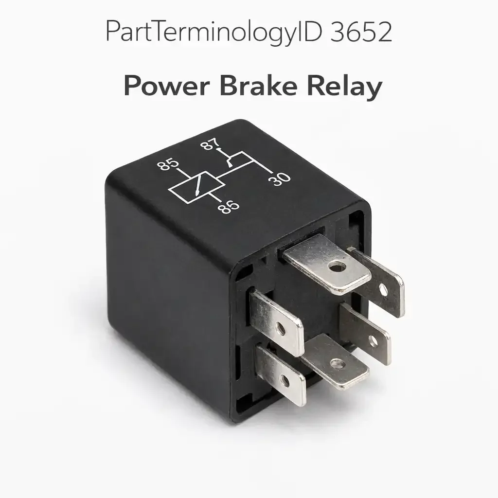
The Power Brake Relay, cataloged under PartTerminologyID 3652, supplies switched power to an electric motor that generates brake assist. It appears in two distinct application contexts. The first is OEM electro-hydraulic brake booster systems, where an electric pump motor pressurizes a hydraulic accumulator that supplies boost force to the master cylinder. The second is aftermarket electric vacuum pump installations, where an electric pump motor generates intake vacuum for a conventional vacuum brake booster on engines that do not produce sufficient vacuum on their own. In both contexts, the relay is the high-current switch that sits between the ignition-switched fuse and the pump motor, and in both contexts the relay is controlled by a pressure or vacuum sensing switch rather than directly by the ignition circuit.
Understanding which application a buyer is describing is the first diagnostic requirement, because the circuit architecture, the fault hierarchy, and the diagnostic approach differ between OEM hydraulic systems and aftermarket vacuum pump systems. A relay that serves a GM Powermaster booster is part of a safety-critical hydraulic circuit developed in the mid-1980s. A relay that serves an aftermarket electric vacuum pump kit is a standard ISO relay typically supplied with the kit. Both use the same basic relay function, but the context for diagnosis, fitment, and return prevention is different for each.
What the Relay Does
OEM Electro-Hydraulic Booster Applications
On GM vehicles equipped with the Powermaster brake system, which appeared on the 1985-1987 Buick Regal Turbo and Grand National and on select full-size station wagons from 1986, the power brake relay supplies current to the electric pump motor that maintains hydraulic pressure in the accumulator. The accumulator stores pressurized brake fluid that the booster uses to multiply pedal force at the master cylinder. When the driver applies the brakes, accumulator pressure drops. Once pressure falls below the threshold set by the internal pressure switch, the pressure switch closes a ground circuit for the relay coil, the relay energizes, power reaches the pump motor, and the pump runs until the accumulator is recharged and the pressure switch opens again.
The Powermaster system is self-contained: its pump, accumulator, master cylinder, and pressure switch are integrated into a single unit mounted in the engine compartment. The relay mounts on the fender or nearby and is the primary electrical switching component outside the Powermaster unit itself. On Buick Reatta, Buick Riviera, Cadillac Allante, and related GM front-wheel-drive platforms from the late 1980s that used electro-hydraulic ABS booster systems, a similar pump relay arrangement appears, with the relay controlling the ABS pump motor that simultaneously serves braking assistance and anti-lock function.
On Bosch Hydro-Max systems used on medium-duty trucks, school buses, and motorhomes, an electric backup motor within the Hydro-Max unit provides brake assist if the power steering pump pressure fails. That backup motor circuit also routes through a relay. The Hydro-Max relay is a legitimate replacement part on these platforms and is available as a new component from specialty suppliers even when the truck manufacturer considers the component obsolete.
Aftermarket Electric Vacuum Pump Applications
High-overlap camshafts in performance engines, diesel engine swaps into vehicles originally designed for gasoline engines, and turbocharged or supercharged engines with pressurized intake manifolds all produce insufficient manifold vacuum to operate a vacuum-type power brake booster reliably. The solution is an electric vacuum pump that generates the required vacuum independently of the engine's intake manifold. The relay in these systems switches power to the vacuum pump motor, and the relay's coil is controlled by a vacuum sensing switch mounted in the vacuum line between the pump and the booster.
When vacuum at the booster drops below the switch's threshold, typically around 15 to 18 inches of mercury depending on the booster's requirements and the system design, the vacuum switch closes the relay coil's ground path, the relay energizes, and the pump runs until vacuum is restored and the switch opens. This prevents the pump from running continuously, which would overheat the pump motor and waste electrical system capacity. The relay is almost always a standard four-pin or five-pin ISO relay, and the vacuum switch is the component that determines whether the system operates correctly.
Top Return Scenarios
Pressure Switch Failure on OEM Hydraulic Systems
The pressure switch on the Powermaster and similar OEM electro-hydraulic systems is the component that controls relay operation. It grounds the relay coil when accumulator pressure is low and opens that ground when pressure is adequate. A pressure switch that fails open means the relay coil never receives a ground, the relay never energizes, the pump never runs, and the driver loses power brake assist after the first few pedal applications deplete accumulator pressure. The symptom is a progressively hardening brake pedal that eventually requires full leg force to stop the vehicle.
A buyer experiencing this symptom often replaces the relay first because it is more accessible and less expensive than the integrated Powermaster unit or the pressure switch, which on these platforms may be internal to the unit. Confirming whether the relay coil receives its ground signal when pressure should be low, by probing the coil's ground terminal with the accumulator depressurized, separates a relay fault from a pressure switch fault. If no ground appears at the coil with the accumulator empty, the pressure switch circuit is the fault. If ground is present and the relay still does not energize, the relay coil has failed.
Pump Motor Failure Misidentified as Relay
On Powermaster systems and aftermarket vacuum pump kits alike, the pump motor can fail to run even when the relay is energizing correctly. A relay that clicks audibly when the coil is energized and delivers supply voltage to the motor output terminal has done its job. If the motor does not respond to that voltage, the motor has failed. The relay's contacts and coil are functional. Replacing the relay in this scenario produces a relay that also clicks and delivers voltage and a motor that also fails to run, and the relay is returned.
Confirming motor supply voltage at the motor's positive terminal, with the relay energized and the motor failing to run, identifies motor failure as the fault before the relay is ordered. On Powermaster systems, motor failure is a known failure mode, and the motor is integrated into the Powermaster unit itself, meaning the entire unit typically requires replacement or rebuilding rather than motor-level replacement. On aftermarket vacuum pump kits, the motor is within the pump assembly and is also typically replaced as a complete pump unit.
Vacuum Switch Failure on Aftermarket Systems
On aftermarket electric vacuum pump installations, the vacuum switch is the component most likely to fail. These switches are inexpensive and sourced from a variety of suppliers, and quality varies widely. A vacuum switch that fails open means the relay coil never receives its ground signal, the relay never energizes, and the pump never runs. A vacuum switch that fails closed means the relay coil receives a constant ground signal, the relay is always energized, the pump runs continuously, and the pump motor overheats.
A buyer with a pump that will not run at all, or a pump that runs continuously and has overheated, may replace the relay before the vacuum switch because the relay is a more familiar component. On aftermarket systems, the relay is a standard ISO unit that can be bench-tested by applying coil voltage and checking contact continuity. If the relay tests functional on the bench, the vacuum switch is the fault. Confirming this before ordering a relay saves the return.
Accumulator Failure Causing Continuous Pump Operation
On Powermaster and similar OEM systems, a failed accumulator causes the pump to run constantly even when no brake application is occurring. The accumulator stores pressurized fluid that maintains system pressure between brake applications. A failed accumulator cannot hold pressure, so the pressure switch's threshold is never reached and the relay coil is continuously grounded. The pump runs without stopping until it overheats, and the relay contacts see continuous current that accelerates contact wear.
A buyer whose pump runs constantly and whose relay has visibly overheated or failed may attribute the relay failure to the relay itself rather than to the upstream cause that forced the relay to carry continuous current. Replacing only the relay without addressing the accumulator failure will produce another failed relay within a short period. Explaining this relationship in listing content, so buyers understand that a failed relay after continuous pump operation is a symptom of accumulator failure rather than an isolated relay fault, prevents the second return when the replacement relay also fails.
Listing Requirements
Every listing for PartTerminologyID 3652 should include:
ACES fitment data distinguishing between OEM electro-hydraulic booster applications and aftermarket electric vacuum pump applications, because the relay specifications differ between these contexts
A clear description of the relay's role: it switches power to the pump motor on command from a pressure switch or vacuum switch, and it is not the component that directly senses system pressure or vacuum
The relay's coil voltage, contact current rating, and body format for each application, because power brake pump motors can draw 10 to 30 or more amperes and relay contact rating is safety-critical in this application
A note that pressure switch or vacuum switch failure is a higher-probability fault source than the relay when the pump fails to run
A note that continuous pump operation before relay failure indicates accumulator failure rather than isolated relay failure, and that accumulator condition should be addressed before relay replacement on OEM hydraulic systems
A statement that this relay is sold as a standalone component and does not include the pump, accumulator, pressure switch, vacuum switch, or wiring harness
Frequently Asked Questions
My power brakes suddenly stopped working and the pump is not running. Is the relay the problem?
Check whether the relay coil is receiving its ground signal from the pressure switch or vacuum switch before ordering a relay. With the accumulator depressurized or the booster vacuum depleted, probe the relay coil's control terminal for a ground signal. If no signal is present, the pressure switch or vacuum switch is the fault. If the signal is present and the relay still does not energize, the relay coil has failed. If the relay energizes and delivers voltage to the motor but the motor does not run, the motor is the fault.
My pump runs constantly and won't stop. Is the relay stuck closed?
A relay with stuck or welded contacts is one possibility, but the more likely explanation on OEM hydraulic systems is accumulator failure. A failed accumulator cannot store pressure, so the pressure switch never reaches its cutoff threshold and the relay coil remains grounded. The pump runs continuously until the motor overheats. On aftermarket vacuum pump systems, a vacuum switch that has failed closed produces the same continuous run symptom. Test the relay independently by removing it and checking whether the contacts open when no coil voltage is applied before assuming the relay is at fault.
Can I use any standard ISO relay in this application?
Contact current rating matters more in this application than in many others. Power brake pump motors can draw substantial current, especially at startup, and a relay with inadequate contact ratings will fail quickly under the load or generate enough heat to degrade nearby components. Confirm the contact rating of any substitute relay meets or exceeds the original specification before substituting. On OEM applications, using the specified relay is preferred.
What Sellers Get Wrong
Listing without specifying contact current rating
A listing that omits the relay's contact current rating leaves buyers without the information they need to confirm they are ordering a relay that can handle the pump motor's electrical load. Power brake pump motors are among the higher-current relay loads in the passenger vehicle fuse block. A relay installed with insufficient contact rating will fail prematurely under load, generate heat at the socket, and potentially damage the socket terminals. Specifying the contact rating for each application in the listing prevents this failure mode.
Not acknowledging the pressure or vacuum switch as the primary fault source
The most common reason a power brake relay is ordered is a pump that has stopped running, and the most common reason a pump stops running is that the pressure switch or vacuum switch controlling the relay's coil has failed. Listing content that presents the relay as the solution to pump-not-running complaints without mentioning the sensing switch drives orders from buyers whose sensing switch is the actual fault. Those buyers replace the relay, observe that the pump still does not run because the switch provides no coil ground, and return the relay.
Mixing OEM and aftermarket applications without distinguishing them
A catalog that groups OEM electro-hydraulic booster relay applications alongside aftermarket electric vacuum pump relay applications without distinguishing between them invites fitment errors. The relay specifications, circuit architecture, and fault diagnosis approach differ between these contexts. Buyers shopping for a Powermaster system relay on a 1986 Grand National and buyers shopping for a replacement relay for an aftermarket vacuum pump kit are solving different problems. Organizing the listing to make this distinction clear serves both buyer populations without confusion.
Cross-Sell Logic
Pressure switch or brake booster pressure switch (the component that grounds the relay coil on OEM hydraulic booster systems and the highest-probability fault source when the pump fails to run on these platforms)
Vacuum switch or vacuum sensing switch (the component that grounds the relay coil on aftermarket electric vacuum pump installations and the highest-probability fault source when the pump fails to run or fails to stop)
Powermaster unit or brake booster pump assembly (the complete unit that integrates the pump, accumulator, and master cylinder on GM Powermaster applications, required when internal failure within the unit is the fault rather than the relay or external switching components)
Accumulator (on OEM hydraulic systems, accumulator failure causes continuous pump operation that stresses the relay; on platforms where the accumulator is a serviceable external component, it should be evaluated whenever the relay has failed from overheating)
Relay socket and wiring pigtail (on older vehicles where relay socket corrosion has compromised contact with the relay terminals, a corroded socket can produce the same no-power-to-motor symptom as a failed relay coil)
Final Take
PartTerminologyID 3652 covers relay applications where the downstream load is a safety-critical brake assist motor. The consequences of a failed relay in this circuit are a hard brake pedal and degraded stopping ability, which means buyers arrive with urgency and sometimes with less diagnostic patience than the situation calls for. The relay is a legitimate fault source, but the pressure switch on OEM hydraulic systems and the vacuum switch on aftermarket installations are more probable faults in a non-running pump complaint, and accumulator failure is the explanation that sellers must address when a relay has failed after sustained continuous pump operation.
The listing that serves this buyer best is the one that makes the relay's role in the circuit clear, explains the sensing switch's role in controlling the relay, and gives the buyer the one-step test that tells them whether the relay coil is receiving its trigger before they order. That buyer arrives knowing the relay is their fault, installs it, and has power brakes again. That is the only outcome that prevents a return in this category.