Multi-Purpose Relay (PartTerminologyID 3608): Diagnosis, Return Prevention and Listing Guide
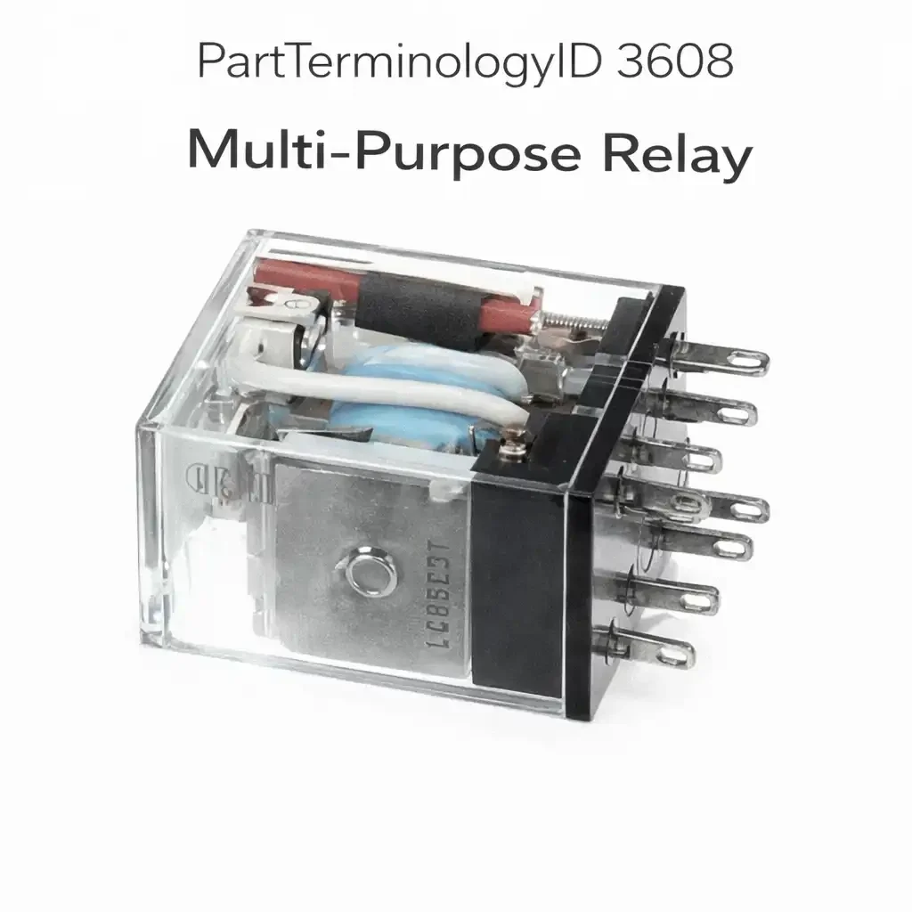
The Multi-Purpose Relay, cataloged under PartTerminologyID 3608, is the designation OEM engineers assign to a standard ISO electromechanical relay that a manufacturer has chosen not to dedicate to a single named circuit function. Where the fuel pump relay carries a dedicated PartTerminologyID for fuel pump circuits and the cooling fan relay carries a dedicated PartTerminologyID for fan circuits, the multi-purpose relay is the relay a manufacturer has designed into its fuse block in a socket position that may serve different circuit functions depending on vehicle trim level, option package, regional market, or model year revision. It uses the same underlying relay technology as every other ISO plug-in relay in the fuse block. The coil energizes when a control signal is applied, the armature closes the contacts, and the load circuit is completed. What makes this relay category distinct is not its internal mechanism but the cataloging decision behind it: the relay serves multiple possible purposes across applications, and the part number that describes it is defined by its physical and electrical specifications rather than by the single circuit function it governs.
In practice, a multi-purpose relay position in an OEM fuse block is a standardized socket that the vehicle manufacturer populates with a relay meeting a specific coil voltage, contact rating, body format, pin count, and suppression specification for whichever circuit occupies that socket position on a given vehicle. On a base-trim vehicle without certain options, the socket may be empty. On the fully equipped version of the same model, the socket may carry a relay governing the heated seat circuit. On a fleet version of the vehicle built for a specific market, the same socket position may govern an auxiliary lighting relay. The relay itself is identical across all of these applications in its physical specification, which is why it is sold under a multi-purpose description rather than a circuit-specific one. Sellers who understand this distinction build better listings, reduce returns, and support buyers who are working from fuse block diagrams that label a position simply as "Multi-Purpose Relay" without naming the specific function it serves on their vehicle.
What the Relay Does
Electromechanical Switching Fundamentals
The multi-purpose relay operates on the same fundamental principle as every other electromechanical relay in a vehicle's fuse block. A low-current control circuit energizes a wound coil around a ferromagnetic core. The resulting magnetic field pulls a hinged armature toward the core against the resistance of a return spring. The armature movement closes the load circuit contacts, allowing current to flow from the relay's common terminal through the normally-open contact to the downstream load. When the control circuit de-energizes, the return spring pulls the armature back to its resting position, the contacts open, and the load circuit is interrupted.
The electrical isolation between the control circuit and the load circuit is the relay's defining advantage. A control signal that might carry only a few milliamps from a module output driver, a switch, or a BCM pin can switch a load circuit carrying ten, twenty, thirty, or more amps without the high-current path ever touching the low-current control path. This allows vehicle engineers to protect sensitive module output drivers from the inrush current and arc energy of high-current loads, to route high-current wiring efficiently within the engine bay or body, and to allow a single module output to control a load that exceeds the module's direct switching capability.
Multi-Purpose Socket Positions in Fuse Block Architecture
Modern vehicle fuse blocks, whether located in the engine compartment power distribution center or in the body fuse panel inside the passenger compartment, are designed with a mix of dedicated relay positions and multi-purpose relay positions. Dedicated positions are wired directly to specific circuits during vehicle assembly and carry unique electrical connections determined by the circuit function they serve. Multi-purpose positions are wired to generic circuit paths that can serve different functions depending on which harness variant is installed during assembly, or which software calibration is loaded into the BCM.
From a manufacturing efficiency standpoint, using a standardized relay in a multi-purpose position allows a single relay SKU to be shared across multiple vehicle variants and option combinations. Rather than designing a unique relay for every circuit function on every trim level, the manufacturer designs a relay position to a standard electrical specification: typically a twelve-volt coil, a thirty-amp or forty-amp contact rating, a four-pin or five-pin ISO body, and a resistor or diode suppression component. Any relay meeting that specification can populate any multi-purpose socket position on any variant of that platform. The fuse block cover legend on a specific vehicle then names the function assigned to that position on that vehicle, whether it is a rear window defogger relay, a trailer brake relay, a heated mirror relay, an accessory power relay, or any other moderate-current switched supply.
Coil Operation and Control Signal Sources
The multi-purpose relay coil in a fuse block position is triggered by one of several possible control signal sources depending on the circuit it serves. Direct ignition switch outputs supply coil voltage for relays that must be active whenever the ignition is in the run position. BCM or body module output pins control relays for functions the vehicle's body electronics govern, such as door locks, interior lighting control, accessory power sequencing, and driver personalization features. Switched ground paths from module outputs complete coil ground circuits for relays where the coil positive terminal is connected to a continuous battery supply and the module pulls the ground side of the coil to switch the relay. Manual switches or momentary pushbutton inputs from the driver or passenger supply control signals for relays governing user-controlled accessories.
The coil voltage and coil resistance specification of the multi-purpose relay must match the electrical design of the control circuit it serves. A coil that draws more current than the module output driver can safely supply will stress the driver transistor and potentially cause module damage over time. A coil that draws significantly less current than the driver was designed to supply will still function but may be more susceptible to voltage spikes causing false triggering. OEM engineers specify coil resistance with the module output driver's current capacity in mind, which is why a generic multi-purpose relay that appears identical to the OEM part may have a coil resistance outside the specified range for a given application.
Load Circuit Functions and Current Ratings
The load circuit of a multi-purpose relay supplies battery voltage or switched ignition voltage to the downstream component or circuit that the relay controls. For fuse block positions carrying the multi-purpose designation, the load circuit function varies by vehicle and by the specific option content of that vehicle. Common circuits served by multi-purpose relay positions include auxiliary power outlets that remain active for a defined period after ignition off, rear window defogger grid supply circuits, heated seat element supply circuits, power running board motor supply circuits, trailer tow accessory supply circuits, secondary horn relay positions, occupant detection module supply circuits, satellite radio module supply circuits, fuel pump relay positions on platforms where the fuel pump relay is shared across multiple engine variants, and secondary cooling fan relay positions.
The contact rating of the relay must be appropriate for the sustained current draw of whatever load occupies that multi-purpose socket position. A relay specified at thirty amps continuous can serve circuits drawing up to approximately thirty amps without contact overheating and pitting. Installing a relay rated below the circuit's actual sustained current draw produces contact wear that shortens relay life and eventually causes intermittent or complete circuit failure. Installing a relay rated above the specified current does not harm the circuit but may conflict with the physical specification of the OEM relay if the higher-rated version uses a larger body format. The aftermarket buyer ordering a multi-purpose relay must confirm the contact rating specified for their vehicle's fuse block position rather than assuming any relay with the correct body format is acceptable.
Normally-Open, Normally-Closed, and Changeover Configurations
The vast majority of multi-purpose relay positions in modern vehicle fuse blocks use normally-open four-pin relay configurations where the load circuit is open at rest and closes when the coil is energized. This is the default configuration for relays governing switched accessory circuits, fuel pump circuits, cooling fan circuits, and most body electrical load circuits. The load is off until the relay is commanded on, which is the expected behavior for accessories that should not energize without a deliberate control signal.
A smaller number of multi-purpose relay positions use five-pin changeover configurations where the relay switches between a normally-closed output and a normally-open output simultaneously. These positions appear in circuits requiring direction reversal logic, default-state power paths, or interlock logic where one circuit must be active when the relay is at rest and a different circuit must be active when the relay is energized. Installing a four-pin normally-open relay in a position that calls for a five-pin changeover relay will cause the circuit to function only in the energized state and will leave the circuit path that depends on the normally-closed output permanently open.
Top Return Scenarios
Wrong Body Format for the Fuse Block Socket
The most frequent return in the multi-purpose relay category results from a buyer who selects a relay based on coil voltage and contact rating without verifying that the relay's physical body format matches the socket in the target fuse block. Multi-purpose relay positions appear in mini relay sockets, micro relay sockets, and in some platforms, Micro 280 format sockets that differ in pin blade width from standard ISO mini and micro formats. A relay that matches the circuit specification exactly but comes in the wrong body format cannot be correctly installed. Because multi-purpose relay listings often aggregate broad applications under a single SKU to maximize reach, buyers on micro relay applications order mini relay parts and vice versa. The return is processed as incorrect fitment, but the root cause is a listing that did not require the buyer to confirm body format before ordering.
Preventing this return requires that every multi-purpose relay listing explicitly state the body format in the product description and require the buyer to confirm it during the ordering process. A listing that describes the part as a thirty-amp four-pin ISO relay without stating whether that relay is a mini or micro format will generate format mismatch returns from a predictable proportion of buyers on every application where both formats exist.
Incorrect Pin Count for the Socket Position
A four-pin relay installed in a five-pin changeover socket leaves the normally-closed output terminal unconnected, producing a circuit that fails to deliver its default-state behavior. A five-pin relay inserted into a four-pin socket cannot seat fully because the fifth pin has no cavity in the socket base. Both scenarios produce a return. The buyer who installs a four-pin relay in a five-pin socket may not immediately recognize the problem if the normally-closed path failure mode is subtle, for example if the circuit in question is a backup power path that is only critical under specific operating conditions. The buyer who discovers the five-pin relay won't seat returns the part immediately.
Multi-purpose relay listings that cover mixed four-pin and five-pin applications in a single listing without requiring the buyer to select pin count before purchase will generate pin count mismatch returns consistently. Separating four-pin and five-pin applications into distinct listings, or using a mandatory option selector that forces the buyer to choose pin count, eliminates this return category.
Suppression Component Mismatch on Module-Driven Positions
Many multi-purpose relay positions in modern vehicle fuse blocks are controlled directly by BCM output pins, PCM auxiliary output drivers, or other module output transistors. Module output drivers have defined maximum current capacities, and the relay coil must draw within that capacity to avoid stressing the driver. More importantly, when the module de-energizes the relay coil by removing the control signal, the collapsing magnetic field in the coil generates a voltage spike that, if not suppressed, returns through the control circuit and can damage the module output transistor over many switching cycles.
The OEM relay for a module-driven multi-purpose position almost always includes an internal suppression component. This component is either a resistor in parallel with the coil terminals, which clamps the inductive kick to a level the module can tolerate, or a diode across the coil terminals, which shorts the reverse voltage spike before it can propagate back to the module. A generic multi-purpose relay that lacks the specified suppression component, or that includes a different suppression type than the OEM relay, can cause cumulative damage to the controlling module even though the relay itself functions correctly in the short term. The module failure that appears months later will not be connected to the relay replacement by the buyer or by the technician who subsequently diagnoses the module fault, which means this mismatch does not produce a relay return but does produce a significant downstream consequence.
Listing content that identifies the suppression component type for each application, and that warns buyers not to substitute an unsuppressed relay in any position described as module-controlled, prevents this consequence. For diode-suppressed relays, the installation polarity requirement must also be stated: a diode-suppressed relay installed with reversed coil polarity will forward-bias the diode continuously, damage the diode, and potentially damage the module.
Inoperative Circuit That Is Not the Relay
Buyers who are working through a circuit diagnosis and have arrived at the relay as the presumed fault frequently purchase and install a replacement relay, discover the circuit remains inoperative, and return the relay as defective. In many of these cases, the relay is functioning correctly and the fault is elsewhere: a blown fuse in the load circuit, an open in the wiring harness between the relay output and the load, a failed downstream component, an absent or incorrect control signal at the relay coil, or a corroded relay socket that prevents the relay contacts from making a reliable connection with the circuit even after the relay body is replaced.
A listing that includes a brief diagnostic sequence before and after relay replacement reduces these returns by setting buyer expectations and steering buyers toward root cause diagnosis rather than direct relay replacement. Buyers who confirm that the relay coil terminal is receiving a control signal, that the load terminal is fused and the fuse is intact, and that the relay socket pins are clean and making solid contact before ordering are less likely to return a part that was never the fault.
Contact Welding from Persistent Downstream Fault
A multi-purpose relay whose load circuit is subject to a recurring short circuit or sustained overcurrent condition will fail through contact welding, where the arc energy during repeated contact closure and interruption under fault current causes the contact surfaces to fuse together. A welded relay contacts in the closed position, producing the symptom of a circuit that cannot be switched off: a fuel pump that runs with ignition off, headlights that stay on after the switch is opened, or an accessory that remains powered when it should have been de-energized. The buyer replaces the relay, the new relay welds shut within a short time because the downstream fault has not been corrected, and the second relay is returned as defective.
Listing content that warns buyers of contact welding as a symptom of a downstream fault rather than a standalone relay defect, and that instructs buyers to confirm fuse continuity and test for wiring shorts before installing the replacement relay, reduces these double-failure returns. Any relay returned with welded contacts should be flagged in the return process: welded contacts indicate that a downstream fault caused the failure, not an internal relay manufacturing defect, and that the replacement relay will fail in the same manner unless the downstream fault is diagnosed and corrected.
Listing Requirements
To meet minimum catalog accuracy standards for PartTerminologyID 3608, every listing should confirm and include the following:
ACES vehicle fitment data populated at the year, make, model, and sub-model level, with the fuse block position confirmed against OEM fuse block documentation identifying the specific socket as a multi-purpose relay position on that vehicle variant
Physical body format explicitly stated as ISO mini, ISO micro, Micro 280, or other format applicable to the target application, with a clear note that the relay body format must match the socket format and that different formats are not interchangeable
Pin count specified as four-pin make-and-break or five-pin changeover for each application, with the contact configuration stated as normally-open, normally-closed, or changeover
Rated coil voltage confirmed as 12V DC for passenger vehicle 12-volt platforms or 24V DC for commercial vehicle 24-volt platforms, with the rated operating voltage range noted where applicable
Rated contact current stated as both the continuous contact rating and, where applicable, the maximum inrush current rating for motor or lamp circuits
Suppression component type identified for each application: no suppression, resistor suppression, or diode suppression, with polarity installation requirement stated for diode-suppressed variants
Coil resistance value or range stated where available for module-driven applications where coil draw must fall within the module output driver's current capacity
OEM part number cross-references and aftermarket equivalent numbers included where available and verified
Explicit statement that the relay is sold as a standalone component without socket, harness pigtail, or fuse block
A note advising buyers to verify the fuse supplying the relay load circuit and the control signal at the coil terminals before installation, to avoid attributing an upstream or downstream fault to the relay
Frequently Asked Questions
How do I find out what circuit my multi-purpose relay position actually controls on my specific vehicle?
The fastest source is the fuse block cover diagram, which lists every relay and fuse position with its circuit assignment for the specific vehicle. If the cover diagram is missing or illegible, the owner's manual contains a fuse and relay identification section with the same information. For vehicles where the cover diagram labels a position as "Multi-Purpose" without naming the circuit, the service manual wiring diagrams for the specific model year and trim level will show the circuit assignment for every relay position in the fuse block. A VIN-specific parts catalog from an OEM dealer parts department can also identify the relay's circuit assignment by cross-referencing the relay position to the harness connector that serves that socket on the specific vehicle. Understanding which circuit the relay controls is the first step in diagnosing whether a relay failure is actually the root cause of the symptom the buyer is experiencing.
Can I use a multi-purpose relay to replace a dedicated relay with the same specifications?
In most cases, yes, provided the multi-purpose relay matches the dedicated relay in every relevant specification: body format, pin count, coil voltage, contact rating, and suppression component type. The PartTerminologyID distinction between a multi-purpose relay and a fuel pump relay or cooling fan relay reflects the cataloging approach used to organize the part, not a difference in the relay's internal construction. An ISO mini four-pin normally-open relay with a 12V coil and a 30-amp contact rating is electrically and mechanically the same component whether it is cataloged as a multi-purpose relay or as a fuel pump relay, provided it includes the same suppression component. The buyer should confirm that every specification matches before substituting a multi-purpose relay part number for a function-specific relay part number, and should be aware that the suppression component specification is the most commonly overlooked detail in this comparison.
My multi-purpose relay clicks when I apply 12V to the coil terminals on the bench, but the circuit still does not work after installation. What should I check?
A relay that clicks on the bench is confirming coil function: the armature is moving. The click does not confirm that the contacts are closing completely or that they are making a reliable connection with the socket terminals after installation. After confirming that the relay clicks and that it tests good for contact continuity on the bench, the in-vehicle diagnostic should check four things in sequence. First, confirm that the coil trigger terminal is receiving the control signal when the circuit is commanded on. Second, confirm that the relay load terminal's fuse is intact and that battery voltage is present at the common input terminal of the relay socket. Third, confirm that the relay is fully seated in the socket, since a partially seated relay may not make contact at all pins despite appearing flush with the socket surface. Fourth, check the socket terminals themselves for corrosion, deformation, or pushed-back pins that prevent the relay blade terminals from making contact even when the relay is properly seated.
How do I test a multi-purpose relay without removing it from the vehicle?
The most practical in-vehicle test uses a relay test adapter that allows voltage measurement at each relay socket terminal while the relay remains installed. Probe the coil terminals with a voltmeter to confirm that the control signal is present when the circuit is commanded on. Then probe the load output terminal to confirm that voltage is present after the relay energizes. If the control signal is confirmed but output voltage is absent and the fuse is intact, the relay contacts have failed. An alternative test is the swap test: if the fuse block contains another relay of identical specification in a different socket position, swapping the suspect relay with the known-good relay determines whether the fault follows the relay body or stays with the socket and wiring. The swap test must only be performed between sockets of identical relay specification to avoid damaging either circuit.
What Sellers Get Wrong
Building a Single Catch-All Listing Without Format Differentiation
The most pervasive error in the multi-purpose relay category is building a single listing that covers every application where a multi-purpose relay is used, without requiring the buyer to select body format or pin count before purchase. Because the PartTerminologyID 3608 designation cuts across mini relay, micro relay, four-pin, and five-pin applications, sellers are tempted to aggregate all of these applications under one listing in the hope of maximizing search coverage. The result is a listing that attracts orders from buyers across all format and pin count variants, a significant portion of whom receive the wrong physical relay for their socket, and a return rate that reflects the full breadth of the catalog gap rather than any quality problem with the relay itself.
The correct approach is to differentiate listings by body format and pin count as the primary catalog attributes, and then to apply fitment data within each listing to the vehicles whose multi-purpose relay positions use that specific format and pin count combination. A seller with mini four-pin, mini five-pin, micro four-pin, and micro five-pin multi-purpose relay applications should build at minimum four listings, each with fitment data covering only the applications appropriate to that format and pin count. The additional listing overhead is justified by the elimination of the format and pin count mismatch returns that a single aggregated listing inevitably generates.
Omitting the Suppression Component Specification
Sellers who list multi-purpose relays without identifying the suppression component type are creating a gap that will not show up immediately in return rates but will surface in downstream consequences for buyers whose applications require suppression. A generic multi-purpose relay sold without suppression component information to a buyer on a BCM-controlled circuit position will produce either a BCM output driver failure over time, if the OEM relay required a suppressed relay and the replacement lacks suppression, or a relay that fails to release promptly after the control signal is removed, if the OEM relay lacked a suppression diode but the replacement includes one. Neither consequence produces an immediate return on the relay, but both produce customer dissatisfaction and potentially expensive downstream repairs that the buyer may attribute to the part seller.
Suppression component type should be treated as a mandatory specification field in every multi-purpose relay listing for every application. For applications where the OEM relay includes a diode, the listing must note the polarity requirement for correct installation. For applications where the OEM relay uses a resistor, the listing should note that the relay is polarity-insensitive at the coil terminals. For applications where no suppression is required, stating that explicitly helps technically informed buyers confirm they are not installing a suppressed relay in a position where suppression would alter the circuit's timing behavior.
Neglecting Coil Resistance Tolerance for Module-Controlled Applications
Relay coils are not manufactured to a single precise resistance value. A twelve-volt relay coil with a nominal resistance of approximately 150 ohms may be within manufacturer specification anywhere from 135 ohms to 165 ohms. For most automotive relay applications, this variation is irrelevant. For applications where the relay coil is driven directly by a module output pin with a defined maximum current capacity, a coil on the low end of the resistance range draws more current than a coil at the nominal value, and a coil significantly below the specification range may exceed the module driver's current limit. Module output drivers in modern BCM and PCM designs are generally robust enough to tolerate coil resistance variation within the OEM specification range, but aftermarket relays that use coil assemblies wound to different specifications than the OEM relay may fall outside that range.
The seller cannot always obtain coil resistance specifications for every application, but for multi-purpose relay applications that are explicitly identified in service documentation as BCM-controlled or PCM-controlled relay positions, including the nominal coil resistance value in the listing content gives technically competent buyers the information they need to verify that the aftermarket relay meets the specification. It also signals to professional buyers that the seller has done the technical work to understand the application, which builds confidence in the listing overall.
Treating the Multi-Purpose Label as an Excuse to Skip Fitment Research
Some sellers assume that because a relay is cataloged as multi-purpose, the fitment data requirements are looser than for function-specific relay categories. This assumption produces listings with thin fitment data that broadly apply to vehicle platforms without drilling down to the trim level, option package, or model year revision that actually determines which relay specification is correct for which position. A multi-purpose relay position on a 2018 pickup platform may use a four-pin mini relay on base trim models, a five-pin mini relay on models equipped with a specific towing package, and a four-pin micro relay on a commercial upfit variant of the same platform. A listing that applies to all three of these variants without differentiation sends incorrect parts to two out of three buyer types.
The multi-purpose relay category demands more fitment research per application than most function-specific relay categories, not less, because the variation in specification across applications within a single fuse block position is typically wider. Sellers who invest in VIN-level fitment verification for their highest-volume applications in this category build a catalog advantage that competitors with loose fitment data cannot easily replicate.
Not Warning Buyers to Diagnose Before Replacing
Multi-purpose relay positions, by virtue of their broad application scope, are frequently ordered by buyers who are working from a vague symptom and have identified the relay as the most accessible part in the circuit. The relay is often ordered and replaced before the buyer has confirmed that the relay is actually the fault, rather than a blown fuse, a corroded socket, a failed downstream load, or an absent control signal. When the relay replacement does not resolve the symptom, the relay is returned as defective. Including a brief diagnostic guidance section in the listing description, covering the three or four most common causes of the symptom associated with the relay's circuit function, filters out buyers who would benefit from a different repair before ordering the relay and reduces returns from buyers who installed a correct relay into a circuit with a non-relay fault.
Cross-Sell Logic
Buyers ordering or returning a multi-purpose relay are candidates for the following related components, which address parallel failure modes, circuit prerequisites, or diagnostic tools relevant to the multi-purpose relay category.
Fuse for the relay load circuit (the fuse protecting the circuit that the multi-purpose relay controls is the first component to check before attributing an inoperative circuit to the relay; a blown fuse produces an identical symptom to a failed relay and is the more common fault; the correct fuse amperage must match the circuit specification)
Relay socket or socket pigtail (corrosion, heat damage, or mechanically deformed terminal cavities in the relay socket produce intermittent or absent contact between the relay blade pins and the socket terminals regardless of relay condition; a socket that shows discoloration, melted plastic, pushed-back terminals, or heavy green-white oxidation should be replaced alongside the relay)
Relay tester or test adapter (a bench relay tester that applies 12V to the coil terminals and tests contact continuity across the load terminals allows the buyer to confirm relay function before and after installation and to verify that a returned relay is genuinely defective rather than victim of a misdiagnosis; including this as a cross-sell item serves technically motivated buyers and reduces the reflexive return that follows a non-relay fault diagnosis)
Body control module or BCM (on multi-purpose relay positions that are identified as BCM-controlled, persistent relay failure despite correct relay specification may indicate that the BCM output driver governing the coil circuit has failed and is either failing to energize the coil or applying continuous voltage that causes the relay to remain energized; a replacement BCM is appropriate when relay replacement with a correctly specified part fails to restore correct circuit operation and the control signal at the coil terminal is confirmed absent or always present)
Wiring harness repair kit or pigtail connector (an open or high-resistance condition in the wiring between the relay socket and the downstream load, or between the relay socket and the control module, produces a symptom identical to relay failure; buyers who have confirmed the relay functions correctly on the bench but whose circuit remains inoperative after relay replacement need wiring diagnosis and potentially a harness repair pigtail for the affected segment)
Dielectric grease or electrical contact cleaner (cleaning oxidized relay socket terminals and applying a thin film of dielectric grease at installation prevents corrosion from forming at the blade pin contacts and extends the service life of both the relay and the socket; this is a particularly important recommendation for multi-purpose relay positions in underhood fuse blocks where heat cycling and moisture exposure accelerate terminal corrosion)
Final Take
PartTerminologyID 3608 is a category built on a cataloging decision rather than a circuit function, and that distinction creates both the main challenge and the main opportunity for sellers who work this part number seriously. The challenge is that without a single defined circuit function to anchor fitment research, the specification variation across applications is wide and the consequences of misapplication are spread across format mismatches, pin count errors, suppression omissions, and contact rating mistakes in ways that a function-specific relay category tends to concentrate into fewer error types. The opportunity is that most competitors in this category treat the multi-purpose designation as permission to build loose, undifferentiated listings, which means the seller who does the fitment work correctly stands out in a crowded field.
The seller who builds the strongest catalog for PartTerminologyID 3608 structures their listings by body format and pin count first, populates verified fitment data at the trim and option package level for each format variant, specifies suppression component type and coil polarity requirements for every application, and equips the listing description with enough diagnostic guidance to filter buyers who have not yet confirmed the relay is the actual fault. That combination of physical specification accuracy, fitment depth, and buyer guidance addresses every major return scenario in the category and builds the kind of customer experience that drives repeat business from technicians and DIY buyers who are capable of recognizing when a seller has done the technical work that most in the market have not.
The multi-purpose relay is fundamentally an ordinary relay sold under a label that acknowledges its versatility. The seller's job is to translate that versatility into precision: every buyer who lands on a listing for PartTerminologyID 3608 should leave knowing exactly which relay they need for their specific application, why it is the correct specification, and what to check in their vehicle before and after installation to confirm the relay is the actual fault they are resolving.