Engine Intake Manifold Heater Relay (PartTerminologyID 3580): Diagnosis, Return Prevention and Listing Guide
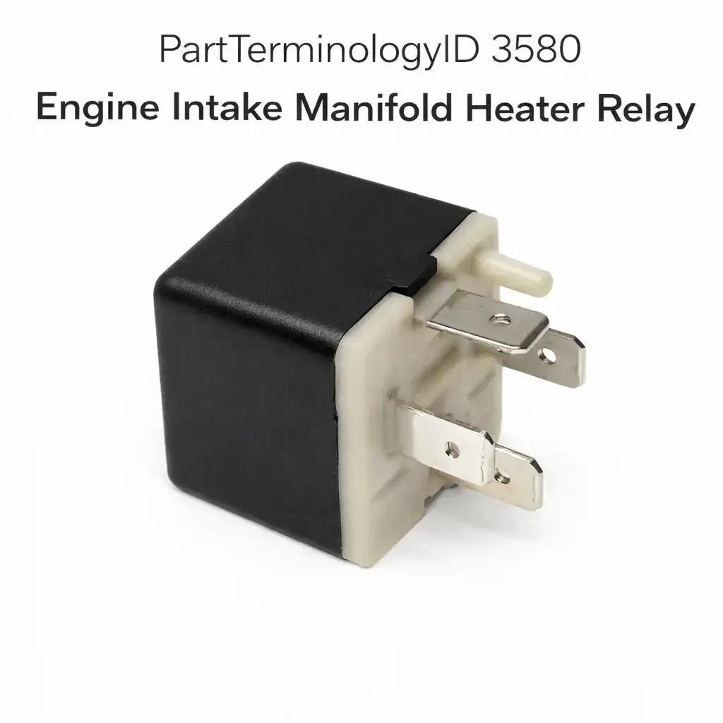
The Engine Intake Manifold Heater Relay, cataloged under PartTerminologyID 3580, is the high-current switching device that delivers battery voltage to the intake air heater element or heater grid assembly mounted at the intake manifold air inlet. On diesel engines that use this system, the heater element sits directly between the air horn and the intake manifold and heats incoming air before and during cold cranking to improve ignition quality, shorten crank time, and reduce white smoke during warm-up. The relay handles the full current load of the heater element, which typically ranges from 100 to 200 amps depending on element rating, and is controlled by a low-current signal from the engine control module or a dedicated heater timer module that monitors intake manifold temperature and coolant temperature to determine when and how long heating is required.
The intake manifold heater relay is primarily a diesel engine component. Gasoline engines achieve adequate cold-start mixture preparation through enrichment strategies managed by the fuel system, so they have no need for intake air heating. Diesel engines, by contrast, depend on compression heat alone to ignite fuel, and in cold conditions the incoming air temperature at top dead center may not reach the threshold required for reliable ignition without supplemental heat. The relay is what allows the ECM to switch the high current required by the heater element without routing that current through the ECM's own output circuits. Sellers building ACES fitment data for PartTerminologyID 3580 are working primarily with diesel truck, van, commercial vehicle, and heavy equipment platforms, and must account for meaningful variation in relay rating, configuration, and control architecture across those applications.
What the Relay Does
Intake Air Heating for Cold Start and White Smoke Control
The heater element energized by this relay serves two distinct operational phases. During the pre-heat phase, which corresponds to the wait-to-start lamp illumination period on equipped vehicles, the ECM or timer module energizes the relay before the driver cranks the engine. The element heats incoming air so that when fuel is injected and the piston reaches top dead center, the air charge temperature is high enough to support reliable ignition even in extreme cold. On applications where the ECM controls the relay directly, it calculates preheat duration from intake manifold temperature and sometimes coolant temperature, with longer preheat times at lower temperatures. The wait-to-start lamp extinguishes when the ECM determines that preheat is complete and the engine is ready to crank.
During the post-start phase, the ECM may continue to cycle the relay on and off after the engine fires and begins to warm up. This post-start heating reduces unburned fuel in the exhaust stream, which is the cause of the characteristic white smoke that diesel engines produce during cold warm-up. On platforms where the relay cycles during warm-up, the driver may notice voltage gauge fluctuations as the high current draw of the heater element loads the charging system during each on cycle. This behavior is normal and does not indicate a relay or charging system fault.
ECM Temperature-Gated Control Logic
The ECM activates the intake manifold heater relay only when intake manifold temperature falls below a calibrated threshold, typically around 19 degrees Celsius or 66 degrees Fahrenheit depending on the platform. Above that threshold, the ECM determines that incoming air is warm enough for reliable ignition without supplemental heating and does not energize the relay regardless of ignition key position. A vehicle that shows no wait-to-start lamp illumination on a mild day is functioning correctly, not exhibiting a heater relay fault. This temperature-gating behavior is one of the most common sources of misdiagnosis in this category, because buyers who have never observed the wait-to-start lamp during warm weather assume the system has failed and order replacement parts that are not needed.
On mechanically injected diesel platforms without an ECM, a standalone timer module performs the same gating function using input from a temperature sensor mounted on the intake manifold. These timer-based systems were common on pre-electronic diesel trucks and continue to appear in the aftermarket catalog as replacement parts for older fleet vehicles and equipment. The timer module, not a relay coil signal from an ECM, provides the control voltage to the relay on these platforms, and a failed timer module produces an identical symptom to a failed relay from the driver's perspective.
High-Current Circuit Architecture and Dual-Relay Configurations
The heater element draws substantially more current than most automotive relays are rated to handle, which is why intake manifold heater relays are typically larger and more robustly constructed than standard ISO mini relays used elsewhere in the vehicle. On 12-volt systems with high-output heater elements, some platforms split the load across two relays wired in parallel or in sequence, with each relay handling a portion of the total heater element current. On 24-volt commercial vehicle systems, a single relay of appropriate rating may handle the full load. The Freightliner and Cummins ISB architecture is a well-known example of a dual-relay setup on a 12-volt system, where two relays control the heater element together and a fault in either relay produces a heater fault code.
For sellers, this dual-relay architecture means that a listing covering a dual-relay platform must clearly specify whether the part is a single relay for one-relay-at-a-time replacement or a kit covering both relays. Buyers who order a single relay for a dual-relay platform and install only one often find that fault codes persist or that heating performance is degraded, and return the relay assuming it is defective. Specifying the relay count required for the application and selling in matched pairs where appropriate prevents this return scenario.
Wait-to-Start Lamp Relationship
On vehicles equipped with a wait-to-start indicator, the lamp is controlled by the same timer module or ECM output that governs the relay, and it illuminates for the same duration as the pre-heat cycle. A failed relay that allows no current to reach the heater element does not affect the wait-to-start lamp circuit on most platforms, because the lamp is driven directly by the timer module or ECM output rather than by relay contact closure. This means the wait-to-start lamp can illuminate normally while the heater element is receiving no current due to a failed relay. Buyers who observe the wait-to-start lamp functioning correctly and assume the heater system is intact may not connect cold-start difficulty to a relay fault. Listing content that explains this lamp-independent relay failure mode helps buyers understand why the wait-to-start lamp is not a reliable indicator of relay health.
Top Return Scenarios
Warm-Weather Purchase Based on Assumed Year-Round Symptom
The most consistent return scenario for PartTerminologyID 3580 is a buyer who purchases the relay during warm weather after observing that the wait-to-start lamp does not illuminate and concludes the heater system has failed. Because the ECM gates relay activation on intake manifold temperature, the wait-to-start lamp does not illuminate and the relay does not energize on warm days regardless of component condition. The buyer installs the relay, observes no change in wait-to-start lamp behavior on the next warm-day startup, and returns it. The original relay was functional throughout. Listing content that explains the temperature threshold for heater activation and explicitly states that no wait-to-start illumination on warm days is correct system behavior, not a relay fault, eliminates this return category entirely. It is the highest-volume preventable return for this part number.
Timer Module or ECM Output Failure Producing Relay-Like Symptom
A functioning relay receives no activation signal when the timer module or ECM that is supposed to energize the relay coil has failed. In cold conditions where the heater should activate, a failed timer module produces no coil voltage at the relay socket, the relay does not close, the heater element receives no current, and the engine exhibits hard cold starts. This symptom is identical in driver experience to a failed relay. Buyers who do not test for coil activation voltage at the relay socket before ordering will return the relay when installation produces no improvement in cold-start behavior. Testing for coil voltage at the relay socket in cold conditions, or commanding the heater circuit with a scan tool, identifies the correct fault before the relay is ordered.
Failed Heater Element Misidentified as Relay Fault
A relay that is energizing correctly but whose heater element has failed open or shorted produces a cold-start problem that the buyer attributes to the relay because the two components sit near each other in the same circuit. The relay is closing and delivering voltage to the element terminals, but no current flows because the element's resistance has gone out of specification. Measuring element resistance, which should typically fall between 0.5 and 2 ohms depending on element design, rules out element failure before the relay is ordered. A buyer who skips this step and replaces the relay will return it when cold starts remain unchanged after installation. Element resistance testing is a thirty-second check with a multimeter and should be named explicitly in listing diagnostic guidance.
Relay Contact Damage from Sustained Overload
Intake manifold heater relays fail more frequently at their contacts than in their coil circuits because the load side of the circuit carries extremely high current on every activation cycle. Contacts that have been subjected to voltage spikes from inductive kickback, sustained activation beyond their rated duty cycle, or operation with a partially shorted heater element will develop pitting and resistance that causes intermittent or complete contact failure. A buyer who installs a replacement relay on a circuit with a partially shorted element that is drawing above-rated current will burn out the replacement relay contacts in a short period and return it as defective. The correct repair sequence is to test element resistance, confirm it is within specification, and then replace the relay. If element resistance is low, replace the element before installing a new relay.
Fuse or Fusible Link Failure Upstream of the Relay
The heater circuit is typically protected by a fuse or fusible link rated for the high current of the heater element. A blown fuse or failed fusible link produces a no-heat symptom that is identical to relay failure because the relay has no load-side supply voltage to switch. Buyers who check for coil activation signal at the relay but do not check for supply voltage on the load side of the relay socket will diagnose the circuit incompletely and order the relay when the fuse was the fault. The heater circuit fuse is the first check in any no-heat diagnosis and should be named explicitly in listing content before relay replacement is suggested.
Listing Requirements
To meet minimum catalog accuracy requirements for PartTerminologyID 3580, sellers should confirm and include the following:
ACES vehicle fitment data with year, make, model, engine type, and displacement confirmed against OEM service documentation identifying the heater relay specification for the target application
Relay contact current rating confirmed against the heater element load specification for the target application, with particular attention to platforms using high-output dual-element heater assemblies
Identification of whether the target application uses a single relay or a dual-relay configuration for the heater element circuit, with listing content specifying how many relays the vehicle requires
Relay coil control source identified as ECM output, standalone timer module, or temperature-switch direct control
Confirmation of relay mounting style: bolted heavy-duty relay with stud terminals versus socketed relay format, as these are not interchangeable
OEM cross-reference part numbers where available
Model year range bounded to exclude platform transitions where the heater relay type or element rating changed within the same engine family
Diagnostic pre-purchase guidance directing buyers to confirm activation conditions are met (intake manifold temperature below threshold), check the heater circuit fuse and fusible link, measure heater element resistance, and test for relay coil activation voltage before ordering
Notation that relay replacement will not resolve timer module or ECM output faults, failed heater elements, blown fuses, or open wiring in the heater supply circuit
Confirmation that the relay is sold as a standalone component without heater element, timer module, or wiring harness
Frequently Asked Questions
My wait-to-start lamp lights up but the engine still cranks hard in cold weather. Does that mean the relay has failed?
Not necessarily. The wait-to-start lamp illumination confirms that the timer module or ECM is producing the preheat command signal, but it does not confirm that the relay closed or that the heater element received current. Test for voltage at the heater element terminals during the preheat interval with the ignition on. If voltage is present at the element terminals during preheat but the element is not heating, the element has failed open and must be replaced rather than the relay. If voltage is absent at the element terminals during preheat despite the wait-to-start lamp illuminating, the relay is not closing and is the likely fault, provided the heater circuit fuse and element resistance have been confirmed good.
How do I know if my platform uses one relay or two for the heater circuit?
The most reliable method is the factory service manual for your specific engine and vehicle combination. The wiring diagram for the intake air heater circuit will show whether one or two relays are present in the circuit. On Cummins ISB and ISC engines installed in Dodge Ram and commercial vehicles, two relays are common. On older Cummins 5.9 12-valve mechanical engines, a single relay typically controls the heater element. On International DT466 and similar heavy-duty engines, the configuration varies by vehicle manufacturer and build date. If you are unsure, trace the heavy-gauge wiring from the heater element toward the battery and count the relay mounting points along that wire path.
The relay energizes and I can hear it click during preheat, but I still have white smoke on cold starts. Is the relay at fault?
A relay that clicks is closing its contacts. The question is whether the heater element is drawing current after the contacts close. Connect an amp clamp around the heavy cable that feeds the heater element and observe current draw during the preheat cycle. A functioning heater element will draw 100 amps or more depending on its rating. No current draw despite the relay closing indicates an open element or an open connection between the relay and the element. Low current draw indicates a partially failed element with elevated resistance. White smoke during warm-up after a successful preheat cycle is normal diesel behavior in cold ambient conditions and diminishes as the engine reaches operating temperature. Persistent white smoke at operating temperature is an injection timing or fueling issue, not a heater relay fault.
Can a failed intake manifold heater relay cause engine damage?
Not directly. The heater relay controls a supplemental air heating system, not a primary engine function. A failed relay that prevents heater activation causes hard cold starts, extended cranking, and elevated white smoke during warm-up, all of which increase starter wear and may affect cold-start injection timing. None of these represent internal engine damage risk in the short term. However, repeated extended cranking in very cold conditions without heater function can wash cylinder walls with unburned fuel, diluting oil and causing accelerated wear over time. The relay should be repaired promptly, but a failed heater relay does not constitute an immediate engine safety concern the way a failed oil pressure relay or cooling fan relay would.
What Sellers Get Wrong
Applying fitment without confirming relay current rating matches the heater element
Intake manifold heater elements vary significantly in current draw across engine families and model years. An element designed for a high-output heater assembly may draw 150 or more amps, while a lower-output element on the same engine in a different market or application may draw 80 amps. A relay rated for the lower-output application will fail prematurely under the load of a high-output element even though the physical connector and mounting may be identical. Sellers who build fitment based on engine type and model year without confirming element current draw and relay contact rating will produce returns from buyers on high-output applications whose relays burn out under sustained use. Contact rating verification against element specification is a required step in fitment development for this category, not an optional refinement.
Not explaining temperature-gated activation in symptom descriptions
The most preventable return in this category comes from buyers who misinterpret correct system behavior as a fault. A listing that describes the relay fault symptom as no wait-to-start lamp illumination, without qualifying that this is only a fault symptom when ambient temperature is below the activation threshold, will attract buyers who diagnose their correctly functioning system as failed on a warm day. Every listing for PartTerminologyID 3580 should include an explicit statement that the system only activates below a defined temperature threshold and that the absence of wait-to-start lamp illumination in mild weather is normal. This single piece of content eliminates what is otherwise the most consistent and most preventable return this part generates.
Not distinguishing relay fault from timer module fault in diagnostic guidance
A timer module that has failed produces no coil activation signal at the relay socket, and the resulting symptom is hard cold starts with no wait-to-start lamp illumination in cold conditions, which is diagnostically identical to a failed relay from the buyer's perspective. A listing that names the relay as the diagnosis for this symptom without directing buyers to test for coil activation voltage at the relay socket will generate returns from buyers whose timer module was the fault. The distinction between relay fault and timer module fault requires one test, confirmation of coil activation voltage at the relay socket with intake manifold temperature below threshold, and that test should be described in the listing before relay ordering is suggested.
Omitting the heater element resistance check from pre-purchase guidance
The heater element is the component that most commonly fails in the intake air heater circuit on high-mileage diesel vehicles, and its failure produces a no-heat symptom that is identical to relay failure. An element that has failed open draws no current even when the relay closes correctly, producing no heat and no improvement in cold-start behavior. A buyer who installs a new relay without measuring element resistance will return the relay when cold starts remain unchanged. An element that has partially shorted draws above-rated current, which damages relay contacts and causes premature relay failure. Both failure modes are identifiable with a multimeter before any part is ordered. A listing that names element resistance measurement as the mandatory first diagnostic step after confirming the fuse is intact prevents returns from both of these buyer categories.
Cross-Sell Logic
Buyers diagnosing a hard cold-start or no wait-to-start lamp condition who have confirmed the relay as the cause are candidates for the following related components, which share diagnostic overlap or represent the next logical step if relay replacement does not fully restore heater system function.
Intake manifold heater element or grid assembly (the most common actual cause of no-heat symptoms on high-mileage diesel engines; if relay replacement restores switching function but element resistance is out of specification, the element must also be replaced)
Heater circuit fuse or fusible link (the first circuit check before relay ordering and an appropriate low-cost add-on for any heater circuit repair)
Intake air heater timer module (on mechanical diesel and older electronic platforms where the timer module provides the relay coil trigger; a failed timer module produces a symptom identical to relay failure and is the fault when coil activation voltage is absent at the relay socket)
Intake manifold temperature sensor (the sensor input that determines whether the ECM or timer module activates the heater circuit; a failed sensor that reads falsely warm will prevent heater activation in conditions that should trigger it)
Heavy-gauge heater supply cable (the cable between the relay and the heater element carries the full element current and is subject to terminal corrosion and conductor fatigue on high-mileage vehicles; a high-resistance cable connection causes intermittent heating and relay contact arcing)
Battery and charging system components (the heater element draws 100 or more amps during activation and will expose a weak battery or marginal alternator; buyers replacing the relay on a vehicle with a degraded battery may find that heater activation causes voltage dropout symptoms that persist after relay replacement)
Final Take
PartTerminologyID 3580 is one of the more technically demanding relay categories in the diesel aftermarket because the relay sits at the intersection of high-current power switching, ECM temperature logic, and a cold-start system that only operates in conditions that are difficult to replicate for diagnosis. The temperature-gated activation behavior that makes the system invisible in warm weather is the single largest source of preventable returns in this category, and addressing it directly in listing content produces an immediate and measurable reduction in return volume.
Sellers who perform best on 3580 combine accurate current-rating-verified fitment data with diagnostic content that walks buyers through the temperature threshold explanation, the fuse check, the element resistance test, and the coil activation voltage test in that order before relay replacement is suggested. That sequence rules out every more-common cause of the buyer's symptom before the relay is implicated, and it makes the listing a diagnostic reference that experienced diesel technicians and fleet maintenance managers trust. That trust is worth more than any short-term return reduction, because it is what produces repeat orders when the relay does turn out to be the correct diagnosis.