Instrument Panel Dimmer Relay (PartTerminologyID 3512): Diagnosis, Return Prevention and Listing Guide
The Instrument Panel Dimmer Relay, cataloged under PartTerminologyID 3512, is an electromechanical switching device that controls the supply of voltage to the instrument panel dimmer circuit, enabling brightness adjustment of dashboard backlights and gauge illumination. On applications that use this relay, the dimmer relay acts as the enabling switch for the entire dimmer circuit: without it closed, the dimmer control has no load-side voltage to modulate, and the dashboard backlight operates at either full brightness or no brightness depending on the failure mode. The relay is distinct from the instrument panel illumination relay (PartTerminologyID 3500), which simply switches panel lights on and off with headlamp activation. PartTerminologyID 3512 specifically governs the circuit that allows variable brightness control, making it a functionally critical component on any vehicle where the driver relies on the dimmer for comfortable nighttime driving.
This relay is most commonly found on older and mid-generation vehicle platforms where the dimmer circuit uses a rheostat or potentiometer to vary voltage to incandescent panel lamps. On more recent platforms, brightness control has migrated to pulse-width modulation managed by the BCM or instrument cluster itself, which often eliminates the need for a discrete dimmer relay. Sellers listing this part should confirm whether the target application uses a relay-dependent dimmer circuit or a BCM-controlled PWM system before building fitment data.
What the Relay Does
Dimmer Circuit Activation and Headlamp-Linked Switching
On relay-dependent dimmer systems, the instrument panel dimmer relay is activated by the same park lamp or headlamp signal that enables the illumination circuit. When the driver turns on the parking lamps or headlamps, a control signal energizes the dimmer relay coil, closing the relay contact and delivering voltage to the input side of the dimmer rheostat or potentiometer. The driver then uses the dimmer knob or slider to vary resistance in the circuit, which reduces voltage to the panel lamps and dims their output. If the relay fails to close, the dimmer receives no input voltage and the dashboard backlights remain dark regardless of the dimmer control position. If the relay fails in the closed position, the dimmer circuit remains powered whether or not the headlamps are active, which may allow dashboard lights to illuminate with the ignition on even when exterior lamps are off.
The headlamp-linked activation means that diagnosing a dimmer relay fault requires the headlamps or parking lamps to be active during the test. A buyer who attempts to diagnose the dimmer circuit with the exterior lamps off will find no voltage present at the relay output regardless of relay condition and may incorrectly conclude that the circuit wiring is faulty or that the relay is the wrong part.
Rheostat and Potentiometer Load Supply
The primary function of the dimmer relay contact is to supply steady battery voltage to the input terminal of the dimmer control, typically a rheostat or rotary potentiometer mounted in the headlamp switch assembly or on a separate dash-mounted control. The rheostat positions a wiper along a resistive track. As the wiper moves toward the high-resistance end of the track, more resistance is inserted in series with the panel lamp circuit, reducing current flow and dimming the lamps. At the low-resistance position, nearly full battery voltage reaches the lamps and they operate at or near full brightness.
The relay contact must carry the full current load of the panel lamp circuit, which on vehicles with many incandescent backlight bulbs can be several amperes. Contact resistance in a degraded relay adds voltage drop upstream of the rheostat, which shifts the effective dimming range and may make it impossible to achieve full brightness even with the dimmer at its maximum setting. This symptom is distinct from rheostat failure and requires relay replacement to resolve.
BCM-Controlled and PWM-Based Dimmer Architectures
On late-model vehicles, the dimmer relay as a discrete component has largely been replaced by BCM-managed PWM dimming. In these systems, the BCM receives the dimmer control input position over a multiplexed signal circuit, then generates a pulse-width modulated output signal that controls the duty cycle of current delivered to the panel lamp circuit. Higher duty cycle means more on-time per cycle and brighter lamps. Lower duty cycle means more off-time and dimmer output. Because the BCM handles the modulation digitally, no external relay is required to supply voltage to a rheostat.
On these applications, PartTerminologyID 3512 will not appear in the vehicle circuit. Sellers building ACES fitment data for this part should be aware that applying it to PWM-managed vehicles will generate misapplication returns. The diagnostic distinguisher is whether the vehicle's factory wiring diagram shows a discrete dimmer relay in the panel lamp circuit path or routes the dimmer signal through the BCM directly to the cluster or lamp circuit.
Park Lamp Simultaneity and Dimmer Circuit Dependency
On vehicles where the instrument panel dimmer relay is co-activated with the park lamp relay, the dimmer circuit and the park lamp circuit share the same headlamp switch trigger. A failure of the headlamp switch output that activates both relays will affect both the park lamps and the dashboard dimmer simultaneously. This means a buyer who reports no dashboard backlight and no park lamps at the same time is more likely facing a headlamp switch fault than a dimmer relay fault. The dimmer relay governs backlight brightness modulation, not the basic on/off switching of park lamps. Sellers whose listings do not clarify this distinction will receive returns from buyers who replaced the dimmer relay and still had no park lamps.
Top Return Scenarios
Return Scenario 1: Rheostat or Potentiometer Was the Actual Failed Component
The dimmer rheostat and the dimmer relay produce overlapping symptoms when they fail. A failed rheostat that has developed an open circuit in its resistive track prevents brightness adjustment just as a failed relay does, because both conditions result in no working dimmer output. Buyers who do not bench-test or ohm-test the rheostat before ordering the relay will frequently find that replacing the relay does nothing and return it. Listing language should direct buyers to verify that voltage is present at the relay output terminal before ordering a replacement relay, which confirms the relay as the fault rather than the rheostat.
Return Scenario 2: Application Is a PWM System with No Dimmer Relay
This is the most structurally damaging return category for sellers of PartTerminologyID 3512 because it stems from fitment data that covers PWM-managed vehicles. If ACES data is applied to vehicles that eliminated the discrete dimmer relay in favor of BCM-controlled PWM dimming, buyers will order, receive, and install a relay that their vehicle has no socket for. The part is returned as inapplicable. Sellers should audit fitment data for model year cutoffs where target platforms transitioned from relay-based to BCM-managed dimmer circuits.
Return Scenario 3: Headlamp Switch Fault Masquerading as Relay Fault
The dimmer relay coil requires a control signal from the headlamp switch to close. If the headlamp switch output that triggers the relay is open or intermittent, the relay will not close regardless of its condition. Buyers who replace the relay without confirming the presence of a control signal at the coil terminals will find no change in behavior and return the relay as defective. A coil terminal voltage check with the headlamps on, before relay removal, takes less than one minute and eliminates this return category. Listing language should recommend this check.
Return Scenario 4: Dimmer Fuse Blown Rather Than Relay Failed
On vehicles where the dimmer circuit has a dedicated fuse, a blown fuse produces the same no-dimmer symptom as a failed relay. The fuse is upstream of the relay and protects the entire circuit. Buyers who skip the fuse check and proceed directly to relay replacement will find the new relay has no effect and return it. Preventive listing language that names the dimmer circuit fuse as the first item to check before ordering will redirect a meaningful share of these buyers toward the correct repair.
Return Scenario 5: Incorrect Relay Body Installed in Wrong Socket
Many fuse blocks position relays with physically identical ISO mini housings adjacent to each other. The instrument panel dimmer relay may share a fuse block row with the illumination relay, horn relay, or accessory relay. A buyer who identifies the relay by position rather than circuit label can install a functional dimmer relay in the wrong socket, find no improvement, and return the part. Listings should recommend that buyers identify the relay by the fuse box legend or factory wiring diagram label rather than by position alone.
Listing Requirements
To meet minimum catalog accuracy requirements for PartTerminologyID 3512, sellers should confirm and include the following:
• ACES vehicle fitment data with year, make, model, engine, and trim verified against OEM relay specifications and confirmed for relay-based dimmer architecture (not PWM-managed systems)
• Relay coil voltage rating confirmed as 12V DC for standard passenger vehicle applications
• Contact current rating in amperes, confirmed from part specification sheet, to verify adequacy for the panel lamp load on the target application
• Coil activation source identified as headlamp switch output, park lamp relay co-activation, or BCM-controlled trigger where applicable
• Relay housing type and pin configuration confirmed to match the target vehicle socket (4-pin or 5-pin ISO mini relay, or application-specific form factor)
• Model year range accurately bounded to exclude platform generations that transitioned to BCM PWM dimming
• OEM cross-reference part numbers where available to support buyers sourcing by OEM number
• Diagnostic pre-purchase guidance recommending fuse check, headlamp switch output verification, and rheostat continuity test before relay ordering
• Notation of whether the relay is sold with or without a socket or pigtail connector
• Clear statement that the relay governs dimmer circuit power supply and does not resolve BCM faults, PWM output failures, or rheostat mechanical failures
Frequently Asked Questions
Can a failing dimmer relay cause the dashboard lights to stay at full brightness with no dimming response?
Yes, but only if the relay has failed in the closed position, meaning the contact is stuck closed and continuously supplying voltage to the dimmer circuit regardless of the control signal. In this condition the dimmer circuit is always powered, so the lamps illuminate whenever the ignition is on. However, full brightness with no dimming response is also caused by a failed rheostat that has shorted across its resistive track, bypassing resistance entirely and delivering full voltage to the lamps at all dimmer positions. Both failure modes produce the same symptom. Confirming which component has failed requires testing the relay contact continuity with the coil de-energized. If the contact shows continuity with the coil at rest, the relay has failed closed. If the contact is open at rest and closed only with coil voltage applied, the relay is functioning and the rheostat is the more likely fault.
Will a dimmer relay fault set any diagnostic trouble codes?
On older vehicles with discrete relay-based dimmer circuits and no network integration of the panel lamp system, a dimmer relay fault will not set any scan-tool retrievable codes. The circuit has no feedback sensor that reports dimmer status to the PCM or BCM. On late-model vehicles where BCM manages the dimmer and monitors panel lamp circuit integrity, a failed relay in the power supply path may generate a body electrical fault code related to the panel lamp circuit. The presence or absence of codes depends entirely on whether the target application has active monitoring of the dimmer circuit output.
Is PartTerminologyID 3512 the same as PartTerminologyID 3500?
No. PartTerminologyID 3500 is the Illumination Relay, which switches the panel lamp circuit on and off in response to headlamp activation. It functions as an on/off switch for dashboard backlight power. PartTerminologyID 3512 is the Instrument Panel Dimmer Relay, which supplies voltage specifically to the dimmer control circuit, enabling brightness adjustment. On some vehicle platforms both relays are present in the circuit: the illumination relay closes first to activate the lamp circuit, and the dimmer relay supplies the rheostat so the driver can adjust brightness. On other platforms one relay serves both functions. Sellers should confirm which relay configuration the target application uses before building fitment data for either part number.
How do I test the dimmer relay before replacing it?
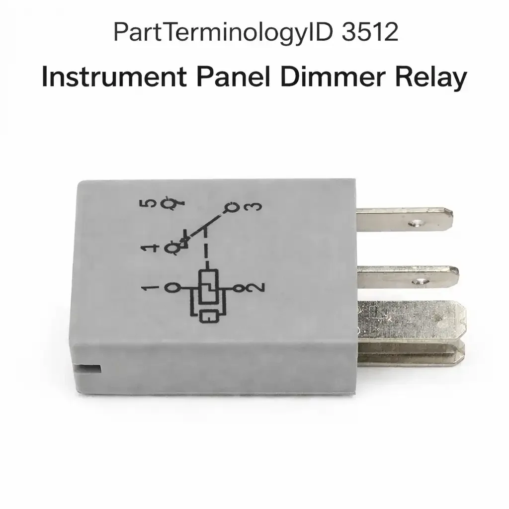
Remove the relay from its socket. Apply 12V DC to the coil terminals, typically pins 85 and 86 on a standard ISO relay. A functioning relay will produce an audible click when the coil is energized and show continuity between the load terminals, typically pins 30 and 87, when tested with a multimeter. With the coil de-energized, the load terminals should show no continuity on a normally open relay. Any deviation from this pattern, including no click, no continuity change, or continuity in the rest state, indicates relay failure. In-vehicle testing should include checking for the presence of the coil trigger voltage at the relay socket with headlamps active and verifying that load-side voltage appears at the relay output when the coil is energized.
What Sellers Get Wrong
Applying fitment data to vehicles that use BCM PWM dimming
This is the single largest source of misapplication returns for PartTerminologyID 3512. Platform transitions from relay-based to BCM-controlled dimming typically happened progressively within a model family across model years. A fitment range that starts in a relay-based generation and extends into a PWM generation without a cutoff will generate steady returns from buyers whose vehicles have no relay socket for this part. Auditing the fitment range against factory service manual circuit diagrams for the transition model year is the correct fix. Applying a blanket fitment based on body style alone is the error.
Listing without distinguishing from the illumination relay
Buyers searching for a no-backlight condition often find both PartTerminologyID 3500 and PartTerminologyID 3512 in search results. If the listings do not clearly explain that 3500 is the on/off switching relay and 3512 is the dimmer supply relay, buyers guess and frequently order the wrong one. Listings for 3512 should explicitly state that this relay controls the dimmer circuit, not the basic illumination circuit, and that a vehicle with no backlight at all rather than non-functioning brightness adjustment may need 3500 instead.
Not directing buyers to check the rheostat before ordering
The rheostat fails more commonly than the relay on high-mileage vehicles because it is a mechanical component with a wiper that experiences wear, carbon tracking, and open-circuit failure over time. A seller who receives a dimmer relay return from a buyer whose rheostat was actually at fault has generated a cost that a single diagnostic note in the listing description would have prevented. The note does not need to be long. Stating that the rheostat should be tested for continuity across its full range of motion before the relay is ordered will redirect the buyer who has the wrong diagnosis.
Omitting the coil trigger source in the listing
The dimmer relay coil requires a specific trigger voltage from the headlamp switch or BCM to close. A listing that does not identify the trigger source leaves buyers unable to verify that the trigger circuit is functional before ordering. Buyers with a failed headlamp switch output will replace the dimmer relay, see no change, and return it. Identifying the coil activation source in the listing sets accurate diagnostic expectations and supports buyers in isolating the fault before purchase.
Cross-Sell Logic
Buyers diagnosing a failed dimmer circuit who have confirmed the relay as the cause are natural candidates for the following components, which share diagnostic overlap or represent the next logical repair step if relay replacement does not fully resolve the symptom.
• Instrument panel dimmer switch or rheostat (most common co-failure with the relay on high-mileage vehicles, often the actual root cause)
• Illumination relay, PartTerminologyID 3500 (buyers with total backlight loss rather than dimming failure may need this relay instead, and listings should cross-reference it)
• Headlamp switch assembly (applications where the dimmer relay coil trigger originates from the headlamp switch and the switch output has failed)
• Instrument panel cluster relay, PartTerminologyID 3508 (buyers replacing backlight components should verify cluster power delivery is also intact)
• Relay socket or pigtail connector (socket corrosion is a parallel failure mode that should be addressed at the same service event)
• Instrument cluster backlight bulb set (buyers restoring dimmer circuit function often discover that individual bulbs have failed during the same repair window)
Final Take
PartTerminologyID 3512 occupies a narrow but well-defined diagnostic position: it governs whether the dimmer control has voltage to work with. When it fails, the symptom is specific enough that a seller who builds the listing correctly can guide buyers to the right diagnosis before they order. The risk is not that the part is hard to understand. The risk is fitment data that reaches into PWM-managed vehicle generations where no relay socket exists, and listings that do not distinguish this relay from the illumination relay clearly enough for buyers to self-sort.
The sellers who minimize returns on 3512 are the ones who bound their fitment data to relay-based platform years, call out the rheostat as the more common failure in the listing description, and make clear in a sentence that this relay controls dimmer circuit supply rather than basic backlight activation. That combination addresses the three largest return categories without requiring a lengthy product description. Short and precise beats long and vague on a relay listing every time.