Ignition Relay (PartTerminologyID 3480): Switched Ignition Supply Circuit, ECM Load Sequencing, Run vs. Crank Contact Configuration, and Contact Current Rating
Written by Arthur Simitian | PartsAdvisory
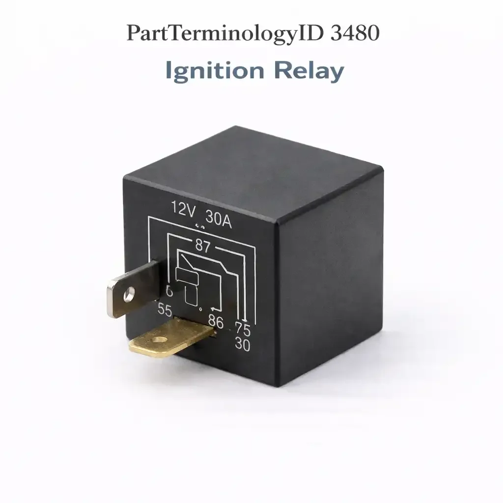
PartTerminologyID 3480, Ignition Relay, is the relay that converts the ignition switch's low-current switched output into a high-current supply feed for the vehicle's ignition-controlled electrical loads, which include the ECM, fuel system components, ignition coils, and a range of other systems that must be powered when the ignition is on and de-powered when the ignition is off. The ignition switch on modern vehicles is a signaling device that carries relatively low current, and the ignition relay amplifies that signal into the supply capacity required by the full aggregate load of the ignition-controlled circuit. The four attributes that determine correct fitment are the contact current rating relative to the total ignition-controlled load the relay supplies; the run versus crank contact configuration on applications where the ignition relay must remain closed during engine cranking as well as during run; the ECM and fuel system load sequencing that occurs in the milliseconds after the relay closes on ignition-on; and the symptom differentiation between a failed ignition relay, a failed ignition switch, and a failed ECM power relay on applications where multiple relays share the ignition-on supply function.
What the Ignition Relay Does
Switched ignition supply and aggregate load current
When the ignition switch is turned to the run or on position, it applies battery voltage to the ignition relay coil terminal through the ignition switch output circuit. The relay coil activates and closes the relay contact, supplying battery voltage from the contact to the ignition-controlled load bus. This load bus distributes ignition supply voltage to every component that requires switched ignition power: the ECM or PCM, the instrument cluster, the fuel pump relay coil, the ignition coil primary circuits, the EVAP purge solenoid, the EGR valve, and a range of other components depending on the vehicle platform. The aggregate current draw of all these components determines the minimum contact current rating for the ignition relay, which typically ranges from 30 to 60 amperes on most passenger vehicle applications. An aftermarket replacement with a contact rating below the aggregate ignition load will run above its thermal rating during normal operation and fail prematurely.
Run versus crank contact configuration
On some applications, the ignition relay contact must remain closed during engine cranking as well as during the run position. On other applications, a separate crank relay or the starter circuit is arranged so that the ignition relay is not required to remain closed while the starter motor is drawing its high inrush current from the battery. The distinction matters because a relay contact that must remain closed during cranking must maintain contact force against the voltage drop produced by the starter motor's heavy current draw reducing battery voltage, sometimes to 9 or 10 volts during cold cranking. A relay contact that opens during cranking due to insufficient coil hold force at reduced battery voltage produces a no-start condition where the engine cranks but does not fire because the ECM, fuel pump, and ignition system lose supply voltage during the cranking event. Confirming whether the application requires a relay with a specified minimum hold voltage during cranking is the critical specification check on applications with intermittent crank-but-no-start complaints.
ECM and fuel system load sequencing
The sequence of events in the milliseconds after the ignition relay closes on ignition-on is the basis for the ECM's initialization and the fuel system's pre-pressurization cycle. When the relay contact closes, the ECM receives its supply voltage and begins its initialization sequence, reading sensor inputs and setting up its operating parameters. Simultaneously, the fuel pump relay coil receives its activation path voltage through the ECM, which commands the fuel pump relay to close and run the fuel pump for a pre-pressurization period before engine cranking begins. A relay contact with elevated resistance that produces a voltage drop to the ECM supply bus can cause ECM initialization faults, intermittent no-start conditions where the ECM does not complete its initialization correctly before cranking begins, or fuel pump pre-pressurization failures if the ECM supply voltage is too low to reliably drive the fuel pump relay coil. Contact voltage drop testing on the ignition relay is the first step when ECM initialization faults or intermittent no-start conditions are present with no other identifiable fault source.
Differentiation from Ignition Accessory Relay (3484) and Ignition Feed Relay (3488)
The Ignition Accessory Relay (PartTerminologyID 3484) supplies the accessory loads that are energized when the ignition is in the accessory position as well as the run position, such as the radio, power windows, and interior lighting. The Ignition Feed Relay (PartTerminologyID 3488) provides an additional ignition supply feed branch for loads that require a separate ignition supply circuit from the main ignition relay output. The Ignition Relay (3480) supplies the core ignition-controlled loads that are required specifically in the run and start positions. On applications with all three relay types, the symptom of no ECM power, no fuel pump activation, and no ignition coil supply on ignition-on points to the Ignition Relay (3480). A symptom of radio and accessories not functioning while the engine starts and runs correctly points to the Ignition Accessory Relay (3484). A symptom of specific secondary loads not functioning while primary ignition loads are correct points to the Ignition Feed Relay (3488).
Top Return Scenarios
Scenario 1: "Engine cranks but does not start, no ECM communication"
A relay contact that fails to close on ignition-on removes supply voltage from the ECM, fuel pump relay coil, and ignition system simultaneously, producing a cranks-but-no-start condition where the scan tool shows no ECM communication because the ECM has no supply voltage. Testing for relay contact output voltage at the ignition-controlled load bus with the ignition on confirms whether the relay contact is supplying the bus. No output voltage with confirmed relay coil activation indicates a failed relay contact. If the relay coil is not receiving activation voltage from the ignition switch, the ignition switch or its output circuit is the fault source upstream of the relay.
Prevention language: "No ECM communication with the engine cranking but not starting is consistent with a failed ignition relay contact removing supply from the entire ignition-controlled load bus. Test for relay contact output voltage at the ignition-controlled bus fuse or connector with ignition on. No output with confirmed coil activation confirms relay contact failure."
Scenario 2: "Engine starts and runs but stalls intermittently with no warning"
An intermittent relay contact that drops out momentarily during operation removes supply voltage from the ECM and fuel system, causing the engine to stall without any prior symptom. This failure mode is difficult to reproduce during diagnosis because the contact resistance is not constant and may pass a static voltage test during a shop visit while still dropping out during vibration or thermal stress during operation. Testing contact voltage drop under ignition load during a road test or with a vibration stimulus to the relay housing identifies a contact with intermittent resistance that a static test would miss. An ignition relay that causes intermittent stalls without any fault codes stored, because the ECM loses power before it can log a fault, is one of the more challenging driveability diagnoses and replacing the relay as a low-cost first step on a high-mileage vehicle with this complaint is reasonable when contact voltage drop testing is not feasible during the visit.
Prevention language: "Intermittent stalls with no fault codes and no warning may indicate an ignition relay contact dropping out momentarily under vibration or thermal stress. Test contact voltage drop under ignition load. An intermittent high-mileage relay with no stored codes is a reasonable low-cost first replacement before more extensive diagnosis."
Scenario 3: "Replaced the ignition relay but the engine still does not start"
Confirm the replacement relay is receiving coil activation voltage from the ignition switch before condemning other components. A failed ignition switch that does not supply the relay coil activation voltage produces the same no-start symptom as a failed relay contact, and replacing the relay does not restore start function if the switch output circuit is open. Test for ignition switch output voltage at the relay coil terminal with the ignition turned on. No voltage at the relay coil terminal confirms the ignition switch or its output wiring is the fault, not the relay. Also confirm the replacement relay part number matches the application's contact current rating requirement, since an undersized replacement may close initially but drop out under the full ignition load current.
Ignition Relay Architecture Across Vehicle Generations
Single ignition relay on early fuel injection systems (1980s through mid-1990s)
Early electronic fuel injection systems used a single main relay, often called the main relay or EFI relay, that supplied the ECU, injector circuits, and fuel pump relay coil simultaneously from one contact. On these applications, the single relay is the equivalent of PartTerminologyID 3480 and its failure produces a complete loss of fuel injection function. Honda and Toyota applications from this era are well-known for main relay failures caused by solder joint cracking on the relay's internal PCB at high ambient temperatures, producing an intermittent no-start condition when the vehicle is hot that resolves after cooling. These platform-specific failure modes are important context for listings targeting these applications.
Multiple ignition supply relays on modern platforms (2000s onward)
Modern vehicle platforms distribute the ignition supply function across multiple relays, each serving a specific subset of ignition-controlled loads. The BCM may command several ignition supply relays in a defined sequence as part of the vehicle's power mode transition from off to run, energizing safety-critical loads before comfort and convenience loads. On these applications, a single relay failure affects only the loads in its supply branch rather than the entire ignition-controlled system. Identifying which relay serves which load branch from the fuse box diagram is the prerequisite for correct relay identification on a partial no-start or partial load-loss complaint on a modern multi-relay ignition architecture.
Relay-less ignition supply on fully BCM-controlled platforms
Some late-model platforms eliminate discrete ignition relays entirely and manage ignition supply distribution through solid-state BCM outputs or smart junction box circuits. On these platforms there is no replaceable ignition relay, and an ignition supply fault is a BCM or smart junction box fault rather than a relay fault. Confirming the application uses a discrete ignition relay before ordering under PartTerminologyID 3480 prevents orders from buyers on relay-less platforms where no relay socket exists for the component.
Listing Requirements
PartTerminologyID: 3480
controlled circuit: ignition-controlled load bus including ECM, fuel pump relay, and ignition coils (mandatory)
contact current rating vs. aggregate ignition load (mandatory)
run vs. crank hold voltage specification where applicable (mandatory)
differentiation from Ignition Accessory Relay (3484) and Ignition Feed Relay (3488) by symptom (mandatory)
relay-less platform application note where no discrete relay is present (mandatory)
OEM part number cross-reference (mandatory)
FAQ (Buyer Language)
My car cranks but will not start. No codes on the scanner. Could this be the ignition relay?
Yes, and no ECM communication on a scan tool during a cranks-but-no-start condition is a strong indicator of an ignition relay fault, since the ECM has no supply voltage to communicate if the relay contact is open. Test for relay contact output voltage at the ignition load bus with the ignition on. No output with the relay coil confirmed active indicates a failed contact. If the scan tool shows no communication with the key on but before cranking, the ECM is not receiving ignition supply power and the relay is the first diagnosis target.
My car stalls randomly with no codes and restarts after a few minutes. Could this be the ignition relay?
Yes, particularly on older applications known for relay PCB solder joint failures at high temperatures. An ignition relay that drops out when the engine compartment reaches operating temperature and then restores function after cooling produces exactly this hot-stall pattern. Check whether the stalls occur more frequently after the vehicle has been running for a while and in warm weather. Testing the relay contact voltage drop under load during the temperature at which stalls occur is the most direct confirmation, but replacing the relay as a low-cost diagnostic step on a high-mileage or high-age vehicle with this pattern is reasonable before more involved diagnosis.
How is the ignition relay different from the ignition accessory relay?
The Ignition Relay (3480) supplies the ignition-controlled loads required to start and run the engine, including the ECM, fuel pump relay activation, and ignition coils. The Ignition Accessory Relay (3484) supplies comfort and convenience loads that are available in the accessory and run positions, such as the radio, power windows, and interior fans. A failed ignition relay prevents the engine from starting or running. A failed ignition accessory relay prevents the radio and convenience features from operating while leaving the engine start and run functions unaffected.
What Sellers Get Wrong About PartTerminologyID 3480
The most common listing error is omitting the contact current rating context. The ignition relay supplies the aggregate current of every ignition-controlled load simultaneously, and this aggregate load is substantially higher than any single component load. An aftermarket replacement listed with a generic contact rating without comparison to the application's aggregate ignition load gives buyers no basis for confirming the replacement is adequately rated. A relay installed below the aggregate load rating will run above its thermal ceiling and fail within one to two seasons, generating a return and a repeat diagnostic visit. The listing must state the contact current requirement for the application and note that aftermarket substitutes must meet or exceed it.
The second most common error is failing to note the relay-less platform exception. Buyers on modern BCM-managed platforms with no discrete ignition relay will find no relay socket when they attempt installation, generating a return that an application confirmation note would have prevented. The listing must identify the application window where discrete ignition relays are present and flag that later platforms may have moved the ignition supply management into the BCM or smart junction box.
The third error is omitting the run-versus-crank hold voltage specification. Buyers on applications with intermittent crank-but-no-start complaints often replace the ignition relay and find that the new relay resolves the complaint, then find it returns on the first cold morning when battery voltage during cranking drops below the relay's coil hold voltage. A relay with an inadequate hold voltage specification for the application's cold-crank battery voltage will drop out during hard cranking. The listing must note the hold voltage specification and recommend confirming it against the application's minimum cranking voltage before ordering.
Cross-Sell Logic
Ignition Accessory Relay (PartTerminologyID 3484): supplies radio, windows, and convenience loads in accessory and run; a failed accessory relay does not affect engine start or run function
Ignition Feed Relay (PartTerminologyID 3488): supplies secondary ignition load branches independently of the main ignition relay; partial load-loss with engine running correctly points here
Ignition Switch: if no relay coil activation voltage is present from the ignition switch when the key is turned to run, the ignition switch output circuit has failed; relay replacement does not restore function when the switch is the fault source
ECM Power Relay (PartTerminologyID 3292 equivalent): on applications where a separate ECM wiring relay supplies the ECM independently of the main ignition relay, ECM communication faults with ignition on may indicate the ECM supply relay rather than the main ignition relay
Final Take for PartTerminologyID 3480
Ignition Relay (PartTerminologyID 3480) is the primary ignition supply relay where aggregate load current rating, run-versus-crank hold voltage, relay-less platform exclusion, and accessory relay differentiation are the four listing attributes that prevent the most common undersized-replacement failures, wrong-platform orders, and wrong-relay orders in the ignition relay category. The aggregate current rating note prevents the most technically consequential wrong-spec installation. The relay-less platform note prevents the most predictable wrong-application order. The run-versus-crank hold voltage note prevents the intermittent cold-start no-start pattern that follows an otherwise correct relay replacement. Sellers who address all four attributes give buyers the complete technical basis to select the correct relay, confirm the correct application, and install a replacement that will perform reliably across the full range of ignition-on and cranking operating conditions.