Horn Relay (PartTerminologyID 3468): Where Horn Coil Current Supply, Horn Button Ground Path, Stuck-Closed Safety Diagnosis, and Dual-Horn Circuit Architecture Determine
Written by Arthur Simitian | PartsAdvisory
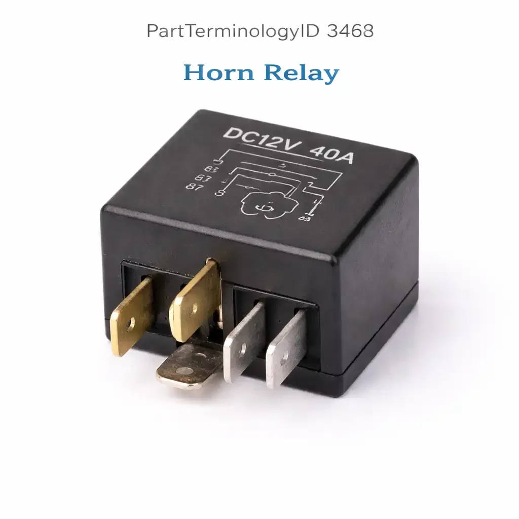
PartTerminologyID 3468, Horn Relay, is the relay that supplies battery voltage to the horn coil or coils when the driver presses the horn button, completing the circuit that causes the horn's diaphragm to vibrate and produce the audible warning signal. The horn relay occupies a specific and frequently misunderstood position in the horn circuit because its coil activation path runs through the horn button to ground rather than from battery to the relay coil directly, meaning the horn button does not switch the horn's full load current but instead switches only the relay coil's low activation current through a ground path in the steering column or airbag clock spring. Understanding this activation architecture is the prerequisite for any accurate horn circuit diagnosis and is the attribute most commonly absent from horn relay listings, generating the highest volume of wrong-component orders when buyers attempt self-diagnosis without this circuit context.
The five attributes that determine correct fitment and prevent the most common return scenarios are the coil activation path through the horn button and clock spring; the contact current rating relative to single or dual horn coil draw; the stuck-closed failure mode that produces a continuously sounding horn and the immediate relay removal procedure that stops it; the horn relay's position relative to the fuse and whether a blown horn fuse points to the relay or to the horn; and the dual-horn circuit architecture present on most passenger vehicles, where understanding which horn or horns are served by which relay prevents ordering the correct relay for the wrong horn position.
What the Horn Relay Does
Horn coil supply and relay contact current
The horn coil is an electromagnetic winding that, when energized, vibrates a metal diaphragm to produce sound. Each horn unit draws between 3 and 8 amperes depending on coil resistance and design, and most passenger vehicles carry two horn units, one tuned to a higher pitch and one to a lower pitch, that sound together when the horn button is pressed. The horn relay contact supplies battery voltage to the horn coil terminals of one or both horn units simultaneously. On applications where both horns are served by a single relay, the relay contact carries the combined current of both coils, typically 6 to 14 amperes. On applications where each horn has its own relay, each relay carries only its individual horn's coil current. The relay contact rating must equal or exceed the full load current of all horn coils served by that relay to prevent contact erosion from operation above the thermal rating.
Horn button ground path and clock spring activation architecture
Unlike most relay circuits where the relay coil is activated by a switched positive voltage from a control module or switch, the horn relay coil is typically held at battery positive voltage constantly at one coil terminal, and the second coil terminal is grounded through the horn button in the steering wheel center when the button is pressed. The circuit path for relay coil activation runs from the constant positive supply terminal, through the relay coil winding, out through the slip ring or clock spring connector in the steering column, through the horn button contact in the steering wheel, and to chassis ground when the button is pressed. A failed clock spring or a broken horn circuit trace in the steering wheel is therefore in the horn relay coil activation path, and a failed clock spring that cannot pass the coil ground signal produces a horn that does not sound when the button is pressed despite the relay, fuse, and horn units all being functional. This is the most common cause of horn failure on vehicles over eight years old and is misidentified as a relay fault in a large share of horn relay orders.
Stuck-closed contact and continuously sounding horn
A horn relay contact that sticks closed produces a continuously sounding horn that does not stop when the horn button is released. This is the most urgent horn relay failure mode because the continuous horn sound is a significant nuisance, may violate local noise ordinances, and cannot be silenced without physically interrupting the circuit. The immediate resolution is to remove the horn relay from its socket in the fuse box. Pulling the relay takes five seconds or less on most applications and immediately silences the horn by removing the power supply from the horn coils. A driver who does not know where the horn relay is located, or does not know that relay removal stops the horn, may instead disconnect the battery or pull the horn fuse, both of which work but have more consequential side effects than relay removal alone. The relay removal instruction for a stuck-closed horn is the most safety-relevant and practically urgent guidance in any horn relay listing.
Horn fuse relationship and overcurrent protection
The horn relay contact output is protected by the horn fuse, which is typically rated between 15 and 30 amperes depending on the number of horns served. The fuse is in series with the relay contact output and the horn coil circuit. A blown horn fuse on a vehicle with no prior electrical work most commonly indicates a short circuit in the horn wiring or a horn coil that has internally shorted and drawn excessive current, rather than a relay fault. Replacing the fuse without identifying the short circuit will produce a repeated fuse failure, usually within the first horn activation after the replacement. A relay fault does not typically blow the horn fuse because a failed-open relay contact draws no current at all, and a stuck-closed relay contact draws only the normal horn operating current which is within the fuse rating. A blown horn fuse in conjunction with normal relay testing warrants horn coil resistance testing and horn wiring inspection before any relay replacement.
Dual-horn architecture and single-horn failure pattern
Most passenger vehicles use two horn units, and on applications with a single shared horn relay, both horns sound together when the relay closes. A single horn that sounds while the other is silent on a dual-horn application indicates a failure at the individual horn unit or its wiring rather than a relay fault, since the relay is supplying both horns from the same contact output and a relay fault would silence both horns simultaneously. Buyers who report that the horn sounds but the tone is weak or different from the original tone have a single horn that is not sounding, and the relay is functioning correctly. Testing each horn unit independently by supplying it directly from a battery confirms whether one or both horns are functional before any relay diagnosis is performed. A single horn failure on a dual-horn application always indicates a horn unit fault or branch wiring fault, never a relay fault.
Top Return Scenarios
Scenario 1: "Horn does not sound when button is pressed, replaced relay but still no horn"
The relay is the least likely single cause of horn failure on a vehicle where the horn previously worked and then stopped. The clock spring, which carries the horn button ground signal through the rotating steering column connection, is the most common failure point on vehicles over five years old because the clock spring ribbon cable fatigues from continuous rotation during steering inputs. A clock spring failure breaks the relay coil activation path without affecting any other horn circuit component, producing a horn that does not respond to button presses regardless of relay condition. Testing for relay coil activation voltage at the relay coil ground terminal when the horn button is pressed confirms whether the button-to-ground circuit through the clock spring is delivering the coil activation signal to the relay. No coil ground signal when the button is pressed confirms a clock spring or horn button fault upstream of the relay.
Prevention language: "Before ordering a horn relay, test for relay coil activation at the relay coil ground terminal when the horn button is pressed. No coil ground signal with button pressed indicates the clock spring or horn button has failed, not the relay. The clock spring is the most common horn failure cause on vehicles over five years old. A relay replacement will not restore horn function if the coil activation signal path through the clock spring is broken."
Scenario 2: "Horn sounds continuously and will not stop"
The horn relay contact is stuck closed. Remove the relay from the fuse box immediately. The relay socket location is typically printed on the inside of the fuse box cover or in the owner's manual. Pulling the relay silences the horn within one second of removal. Do not disconnect the battery or pull the horn fuse as a first response, since battery disconnection resets the radio presets and other volatile memory and horn fuse removal requires locating and replacing the fuse rather than simply reinserting the relay after replacement. With the relay removed, the horn circuit is open and the vehicle can be operated normally without horn function until a replacement relay is installed.
Prevention language: "A continuously sounding horn is a stuck-closed relay contact. Pull the horn relay from the fuse box to stop the horn immediately. The relay location is on the fuse box cover or in the owner's manual. Do not disconnect the battery as a first response. With the relay removed, order a replacement and retest the horn button circuit before assuming the new relay will be the only repair needed, since a stuck relay contact is sometimes caused by excessive current from a shorted horn coil."
Scenario 3: "Horn fuse keeps blowing after replacement"
A repeatedly blowing horn fuse indicates a short circuit in the horn coil or horn wiring rather than a relay fault. Test each horn coil resistance with the horn relay removed from its socket and the horn fuse removed. A horn coil with internal resistance below 1 ohm or measuring as a short circuit between its terminals has failed internally and is drawing fault current that blows the fuse. Replace the shorted horn unit before installing a new fuse. If horn coil resistances are within normal range, inspect the horn wiring for a chafed section contacting chassis ground between the relay contact output and the horn coil terminals. A relay fault does not produce repeated fuse failures.
Prevention language: "A repeatedly blowing horn fuse is not a relay fault. Remove the relay and test each horn coil resistance. A coil measuring near zero ohms has shorted internally. Replace the shorted horn unit before replacing the fuse. Relay replacement does not address a shorted horn coil."
Scenario 4: "Horn tone changed, sounds weaker or different than before"
A changed horn tone on a dual-horn application indicates one horn unit has stopped functioning while the other continues. The relay is supplying both horns correctly. The pitch change or volume reduction is the audible result of one horn sounding alone rather than both horns sounding in concert. Identify which horn unit has stopped by listening for the change in tone, then test each horn unit individually by connecting it directly to a 12-volt supply. The non-functioning horn requires replacement. The relay and horn fuse are functioning correctly and do not require service.
Listing Requirements
PartTerminologyID: 3468
controlled circuit: horn coil or coils (mandatory)
coil activation path: horn button to ground through clock spring (mandatory)
stuck-closed relay removal procedure for continuously sounding horn (mandatory)
clock spring pre-check before relay diagnosis (mandatory)
fuse-blowing short circuit pre-check (mandatory)
dual-horn single-failure pattern as horn unit fault, not relay fault (mandatory)
OEM part number cross-reference (mandatory)
FAQ (Buyer Language)
My horn stopped working. Should I replace the relay first?
Test the relay coil activation path before ordering a replacement relay. With the ignition on, press the horn button and test for a ground signal at the relay coil's ground terminal. A ground signal present when the button is pressed confirms the clock spring and horn button are delivering the coil activation signal correctly and the relay is the appropriate next diagnosis target. No ground signal when the button is pressed confirms the clock spring or horn button circuit has failed and relay replacement will not restore horn function. On vehicles over five years old with no prior horn service, the clock spring is statistically more likely than the relay to have failed.
My horn sounds but is much quieter than it used to be. Is the relay failing?
No. A weaker or different-toned horn with the horn sounding at all confirms the relay is activating the horn circuit correctly. The relay contact is delivering supply voltage to the horn coils and at least one horn is responding. The change in tone or volume indicates one of the two horn units has stopped functioning. Test each horn by direct battery connection to identify which unit has failed and replace that unit. The relay does not require service.
How do I find the horn relay in my fuse box?
The fuse box cover on most vehicles has a printed or embossed legend identifying each relay and fuse position. Look for a relay labeled "Horn," "HRN," or "Horn Relay" in this legend. On vehicles with two fuse centers, the horn relay is typically in the underhood fuse box rather than the passenger compartment fuse box, since the horn units are mounted in the engine compartment. If the fuse box cover legend is missing or illegible, the owner's manual contains a fuse box diagram with relay positions identified by circuit name.
What Sellers Get Wrong About PartTerminologyID 3468
The most consequential listing error is omitting the clock spring pre-check. The horn relay is the first component most buyers replace on a horn failure because it is inexpensive, accessible, and frequently mentioned in forum discussions as the cause of horn problems. In reality, the clock spring fails far more often than the relay on vehicles with significant age or mileage, and the relay replacement rate for horn complaints that are actually clock spring failures is among the highest wrong-component return rates in the body electrical relay category. A listing that does not direct buyers to test for relay coil activation before ordering costs them money, wastes their time, and produces a return for a relay that was never the fault. The clock spring pre-check is the single most return-preventive instruction available for this PartTerminologyID and it must be present in every listing.
The second most common error is omitting the stuck-closed relay removal procedure. A buyer whose horn is sounding continuously needs to know to pull the relay immediately, not to read a diagnostic procedure or wait for a new relay to arrive. The relay removal instruction for a stuck-closed horn contact is the most time-urgent guidance in the listing, more urgent than any diagnostic or installation instruction, because the continuous horn is a live nuisance that can be resolved in five seconds with the right knowledge. A listing that describes relay replacement without mentioning relay removal for a stuck-closed contact fails the buyer at the most critical moment of their experience with this part number.
The third error is failing to note that a changed horn tone is a horn unit fault, not a relay fault. A buyer who hears their horn tone change and searches for a "horn relay" will find this listing and may order the relay based on a general horn complaint without the specific tonal change symptom being identified as a single-horn failure that points to the horn unit. Adding a single sentence noting that a changed or weakened horn tone indicates a horn unit fault rather than a relay fault eliminates a predictable share of these returns before they occur.
Horn Circuit Architecture by Vehicle Generation
Pre-airbag horn circuits (pre-1990)
On vehicles predating airbag systems, the horn button in the steering wheel center pressed directly against a contact ring that completed the horn coil ground circuit through the steering column slip ring assembly. The slip ring is a simple rotating contact rather than the coiled ribbon cable used in clock spring assemblies. Slip ring failure produces the same symptom as clock spring failure, a horn that does not respond to button presses, but the slip ring is a simpler and more durable component than the clock spring and fails less frequently. On pre-airbag vehicles, the horn relay coil activation test is still the correct first step to confirm whether the slip ring contact is delivering the ground signal before the relay is diagnosed.
Airbag-era clock spring circuits (1990 onward)
The introduction of driver airbags required a clock spring assembly in the steering column to carry both the airbag firing circuit and the horn button circuit through the rotating steering column connection without the risk of wire breakage from continuous rotation. The clock spring is a coiled flat ribbon cable that accommodates the full rotation range of the steering wheel while maintaining electrical continuity for all circuits routed through the steering column. The horn button circuit shares the clock spring ribbon with the airbag circuit, the cruise control switches, and any other steering wheel-mounted controls. Clock spring failure affects all of these circuits simultaneously, so a horn failure accompanied by inoperative cruise control switches or an airbag warning lamp strongly suggests clock spring failure rather than a horn relay fault.
BCM-mediated horn activation (2005 onward)
On BCM-controlled horn circuits, the horn button signal is sent to the BCM as an input rather than directly completing the relay coil activation circuit. The BCM evaluates the horn button input and commands the horn relay coil output in response. This architecture allows the BCM to implement horn features such as the single-beep confirmation when the doors are locked via the key fob, or the panic alarm horn cycling. On BCM-mediated applications, a horn that fails to sound when the button is pressed but sounds correctly during key fob lock confirmation indicates the horn relay and horn units are functioning and the BCM is receiving the key fob signal correctly, but the BCM is not receiving or processing the horn button input signal. The fault on this specific presentation is in the horn button signal path to the BCM rather than in the relay circuit.
Cross-Sell Logic
Clock Spring: the most common horn failure cause on vehicles over five years old; a clock spring failure breaks the relay coil activation path and produces a horn that does not respond to the button; clock spring replacement is required before relay replacement restores horn function on this fault
Horn Unit: if relay contact output voltage is confirmed at the horn coil terminals but the horn does not sound, the horn diaphragm or coil has failed mechanically or electrically and the horn unit requires replacement
Horn Fuse: a blown horn fuse removes power from the horn circuit before it reaches the relay contact output; always check the fuse before diagnosing the relay; a repeatedly blowing fuse indicates a shorted horn coil, not a relay fault
BCM: on BCM-mediated horn circuits, a horn that sounds during key fob lock confirmation but not during button presses indicates a horn button signal path fault to the BCM rather than a relay fault
Final Take for PartTerminologyID 3468
Horn Relay (PartTerminologyID 3468) is the horn coil supply relay where the clock spring pre-check, the stuck-closed relay removal procedure, the fuse-blowing short circuit note, and the dual-horn single-failure tonal change explanation are the four listing attributes that prevent the highest volume of wrong-component orders and missed-diagnosis returns across every horn complaint presentation. The clock spring pre-check is the single instruction with the greatest impact on return rate reduction, because clock spring failures outnumber horn relay failures on the population of vehicles generating horn complaint orders and every clock spring failure that is misidentified as a relay fault produces a return that a one-paragraph pre-check instruction would have prevented. The stuck-closed relay removal procedure addresses the most urgent symptom in the entire horn relay complaint set and gives buyers the immediate action that silences a continuously sounding horn in five seconds. Sellers who include all four attributes give buyers the complete diagnostic and emergency response framework for every horn fault presentation, and significantly reduce the return rate on a high-volume, frequently misdiagnosed part number.