Center High Mount Stop Light Relay (PartTerminologyID 3452): Where CHMSL Independent Circuit Architecture, Stop Switch Interaction, and Safety Inspection Compliance
Written by Arthur Simitian | PartsAdvisory
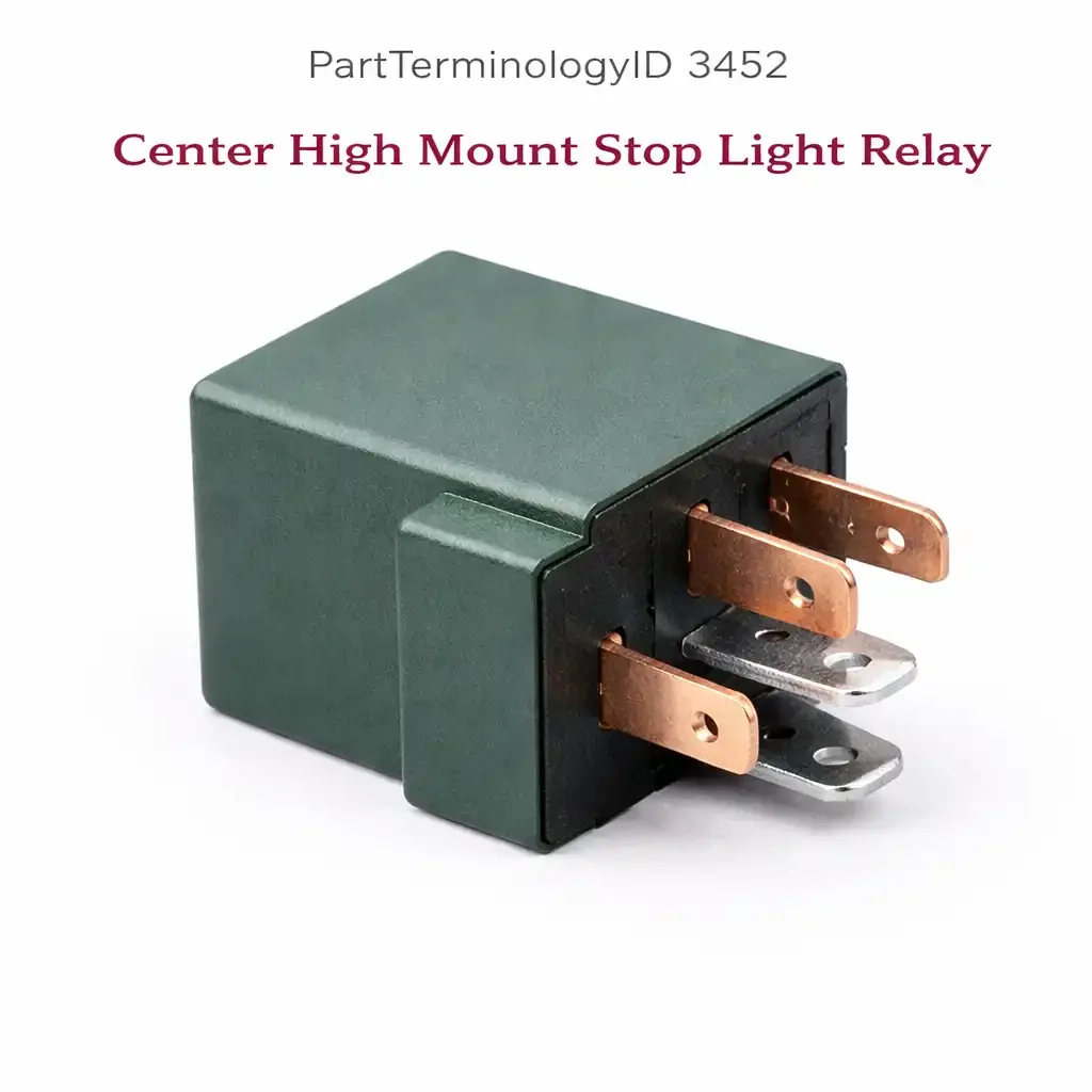
PartTerminologyID 3452, Center High Mount Stop Light Relay, is the relay that supplies the center high mount stop light, commonly referred to as the CHMSL or third brake light, with battery voltage when the brake pedal is pressed, activating the lamp independently of the two outboard stop lamps in the tail lamp assemblies. The center high mount stop light is federally mandated on all passenger vehicles sold in the United States from model year 1986 onward and on light trucks from model year 1994 onward, and its circuit is typically designed to operate independently of the outboard stop lamp circuit so that a fault in one circuit does not disable the other. The three attributes that determine correct fitment and prevent the most common return scenarios are the circuit independence between the CHMSL relay and the outboard stop lamp circuit; the brake light switch signal path that activates the relay coil; and the safety inspection consequence of a non-functioning CHMSL, which creates urgency that can lead buyers to order the first available relay without confirming it matches the application.
What the Center High Mount Stop Light Relay Does
Independent CHMSL circuit and outboard stop lamp differentiation
On applications where a dedicated CHMSL relay is present, the relay supplies the center lamp independently from the main stop lamp circuit that powers the outboard brake lights in the tail lamp assemblies. When the brake pedal is pressed, the stop lamp switch sends a signal that activates both the outboard stop lamp circuit and the CHMSL relay coil simultaneously, but through separate circuit paths that do not share a common relay or fuse. This independent architecture means a failed CHMSL relay produces a center light that does not illuminate when the brakes are applied while both outboard brake lights continue to function normally. Conversely, a failed outboard stop lamp circuit leaves the CHMSL functioning while the outboard lights are dark. The three-light symptom pattern at brake application is the primary differentiating tool: all three dark points to the stop switch; center only dark points to the CHMSL relay or lamp; outboard only dark points to the outboard stop lamp circuit or fuse.
Brake light switch signal path and relay activation
The CHMSL relay coil is activated by the brake light switch signal, which provides battery voltage to the relay coil terminal whenever the brake pedal is depressed beyond the switch actuation point. On BCM-controlled lighting applications, the BCM may intercept the brake switch signal and command the CHMSL relay output directly, allowing the BCM to implement adaptive brake light functions such as progressive braking displays or emergency brake flashers that are separate from the outboard stop lamp function. On these applications, a CHMSL that does not function while outboard lights are correct may indicate a BCM output fault rather than a relay fault, since the BCM controls the CHMSL relay coil independently of the direct switch-to-relay path used for the outboard lamps. Confirming whether the application uses a direct switch activation path or a BCM-mediated path for the CHMSL relay is the first step in diagnosing a CHMSL relay coil activation fault.
Safety inspection consequence and urgency-driven ordering errors
A non-functioning center high mount stop light is a safety inspection failure in most states and jurisdictions, producing immediate registration or operation consequences for the vehicle owner. This urgency drives buyers to order quickly based on symptom description rather than completing the diagnostic steps that confirm the relay is the fault source rather than the lamp, lamp socket, or wiring. The most common urgency-driven ordering error on this circuit is ordering the relay when the CHMSL lamp bulb has simply burned out, since both a failed relay and a burned-out bulb produce the identical symptom of a center light that does not illuminate. A listing that includes the bulb check as the first pre-relay diagnostic step prevents the majority of wrong-component orders in this category, since bulb replacement is far more common than relay failure on the CHMSL circuit.
Top Return Scenarios
Scenario 1: "Center brake light does not come on, outboard brake lights work fine"
Before diagnosing the relay, confirm the CHMSL lamp is not burned out. Access the CHMSL assembly and inspect the bulb or LED element. A burned-out bulb is substantially more common than a relay failure on this circuit and costs a fraction of the relay replacement. With a confirmed good lamp, test for relay contact output voltage at the CHMSL lamp connector when the brake pedal is pressed. No output voltage with confirmed relay coil activation indicates a relay contact failure. No relay coil activation with the brake pedal pressed indicates a BCM output fault or brake switch signal fault upstream of the relay.
Prevention language: "Check the CHMSL lamp before ordering a relay. A burned-out bulb produces the same symptom as a relay failure and is more common. With a confirmed good lamp, test relay contact output at the lamp connector during brake application. No output with confirmed coil activation confirms relay contact failure."
Scenario 2: "All three brake lights stopped working at the same time"
Simultaneous loss of all three stop lamps on a single brake application is a stop light switch fault or a fuse fault upstream of all three stop lamp circuits, not a CHMSL relay fault. The CHMSL relay failure affects only the center lamp. If all three brake lights stopped simultaneously, check the stop light switch, the stop lamp fuse, and the brake pedal position before ordering any lamp or relay component. A CHMSL relay order based on this symptom will produce a return because the relay is not in the common circuit path that supplies all three lamps.
Prevention language: "Loss of all three brake lights simultaneously points to the stop light switch or a fuse in the common supply path, not the CHMSL relay. The CHMSL relay serves only the center lamp. Check the stop light fuse and brake switch before ordering any brake light relay."
Listing Requirements
PartTerminologyID: 3452
controlled circuit: center high mount stop light only (mandatory)
circuit independence from outboard stop lamp circuit (mandatory)
three-light symptom pattern diagnostic (mandatory)
bulb check as first pre-relay diagnostic step (mandatory)
BCM-mediated activation note for adaptive brake light applications (recommended)
OEM part number cross-reference (mandatory)
FAQ (Buyer Language)
My third brake light does not work but my regular brake lights do. Do I need the relay or the bulb?
Check the bulb first. Access the CHMSL assembly from inside the vehicle or through the trunk and inspect the lamp. CHMSL bulbs burn out regularly and the replacement cost is minimal. If the bulb is intact, test for voltage at the lamp connector during brake application. Voltage at the connector with a good bulb and no illumination indicates a bulb socket or ground fault. No voltage at the connector with the brake pedal pressed points to the CHMSL relay or the circuit upstream of it.
My vehicle failed inspection because the third brake light is out. Is the relay the most likely cause?
On a vehicle with no prior electrical work, a burned-out bulb is more likely than a relay failure. Relay failures on the CHMSL circuit are less common than on high-cycling circuits because the stop light relay activates and releases with every brake application, but the current it switches is low relative to circuits like the defroster or fuel pump, which extends contact life. Check the bulb, then the fuse, then the relay in that order. The bulb is the single most common cause of a CHMSL inspection failure.
What Sellers Get Wrong About PartTerminologyID 3452
The most common listing error is omitting the bulb check pre-diagnostic. The urgency of an inspection failure drives buyers to order the first available relay they find, and a listing that describes the CHMSL relay without noting that a burned-out bulb produces the identical symptom will collect orders from buyers who need a two-dollar bulb rather than a relay. The bulb check instruction is the single most return-preventive content element in a CHMSL relay listing. The second most common error is omitting the three-light symptom pattern. Buyers who lost all three brake lights simultaneously need a stop switch or fuse, not a CHMSL relay, and a listing that does not exclude this presentation will generate returns from buyers whose actual fault is upstream of the relay circuit entirely.
Cross-Sell Logic
Stop Light Switch: if no relay coil activation voltage is present at the CHMSL relay when the brake pedal is pressed, and the outboard brake lights are also not functioning, the stop light switch is the fault source common to all stop lamp circuits
CHMSL Lamp Assembly: a confirmed functioning relay with voltage at the lamp connector but no lamp illumination indicates a failed lamp, lamp socket, or ground connection at the CHMSL assembly
Stop Lamp Fuse: a blown stop lamp fuse removes power from all stop lamp circuits simultaneously; always check the fuse before diagnosing any stop lamp relay or switch
Final Take for PartTerminologyID 3452
Center High Mount Stop Light Relay (PartTerminologyID 3452) is the CHMSL supply relay where the bulb check pre-diagnostic, the three-light symptom pattern, and the independent circuit architecture description are the three listing attributes that prevent the highest volume of wrong-component orders in this safety-critical category. The bulb check note alone prevents the majority of relay orders from buyers who have a burned-out lamp and who will order any relay they find under time pressure from an inspection failure. Sellers who include the bulb check as the first listed diagnostic step, describe the independent circuit architecture, and note the three-light all-dark symptom as a stop switch fault rather than a relay fault give buyers the minimum guidance needed to arrive at the correct component for every CHMSL complaint, including the many cases where the relay is not the fault at all.