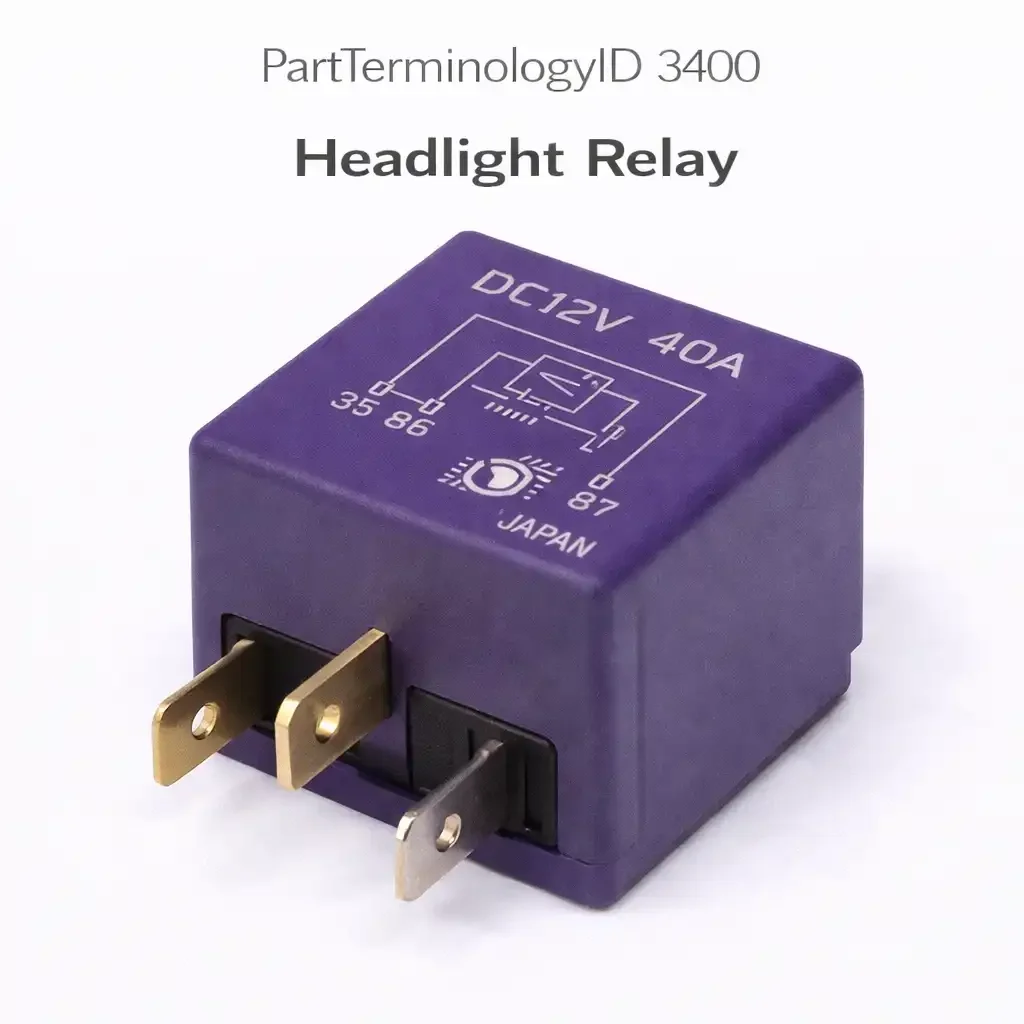
Headlight Relay (PartTerminologyID 3400): Where High-Current Lamp Circuit, BCM Activation Logic, Beam Circuit Identification, and Contact Resistance Diagnosis Determine Correct Headlight Relay Fitment
Written by Arthur Simitian | PartsAdvisory
PartTerminologyID 3400, Headlight Relay, is the relay that supplies high-current battery voltage to the headlight bulb circuit, delivering the sustained current required by halogen, HID, or LED headlight lamp assemblies while protecting the headlight switch or BCM output from carrying the full lamp current directly through the switch contact or module transistor. The relay sits between the battery's fused supply and the headlight lamp connector, allowing a low-current control signal from the headlight switch or BCM to command the relay coil while the relay contact carries the full lamp circuit current independently. The five attributes that determine correct fitment are the specific beam circuit the relay controls; the activation source and how the headlight switch or BCM commands the relay; the contact current rating relative to the lamp wattage; the symptom differentiation between a relay contact fault and a dimmer relay fault on applications that use both components; and the contact resistance consequence on halogen and HID applications where even moderate contact degradation reduces lamp brightness and shortens bulb life by reducing supply voltage below the lamp's design operating voltage.
The headlight relay is one of the most commonly replaced relays in the lighting category and one of the most commonly misidentified, because many applications use multiple relays in the headlight circuit and the symptom of a single failed relay can be identical to the symptom of a failed bulb, a failed dimmer relay, or a failed headlight switch, depending on which relay has failed and which beam circuit it controls.
What the Headlight Relay Does
High-current lamp supply and switch protection function
Before the widespread adoption of relay-controlled headlight circuits in the late 1970s and early 1980s, the headlight switch carried the full headlight current directly through its contact, typically 10 to 20 amperes for a two-headlight system or 20 to 35 amperes for a four-headlight system with dual filament bulbs. Headlight switch contact failure from sustained high current was one of the most common electrical failures on vehicles of that era. The introduction of the headlight relay moved the high-current path to a relay contact in the engine compartment fuse and relay center, reducing the headlight switch to a low-current control duty that extends its service life substantially. The relay contact in the engine compartment receives the full lamp current continuously during headlight operation, and is the component subject to contact erosion, contact resistance increase, and eventual contact failure from this sustained current load.
Beam circuit identification and multi-relay headlight architectures
Many applications use separate relays for the low beam and high beam circuits rather than a single relay for all headlight operation. On four-relay headlight architectures, individual relays control the left low beam, right low beam, left high beam, and right high beam independently, allowing precise circuit isolation for each lamp. On two-relay architectures, one relay controls both low beam lamps together and a separate relay controls both high beam lamps together. The symptom pattern identifies which relay has failed: both low beams out with functioning high beams indicates the low beam relay has failed; one low beam out with the other functioning indicates either a single lamp failure on a four-relay architecture or a wiring fault rather than a relay fault on a two-relay architecture. Listings must identify which beam circuit the relay controls and how many relays the application uses for the headlight system.
Activation source: headlight switch, BCM, or lighting control module
The headlight relay coil activation source varies by application generation. On applications from the late 1970s through the early 1990s, the headlight switch directly grounds or supplies the relay coil when the headlights are switched on. The relay follows the switch position with no module intermediary. On applications from the mid-1990s onward with BCM-integrated lighting control, the BCM receives the headlight switch input signal and commands the relay through a BCM output transistor. On these applications the relay coil activation is a BCM output rather than a direct switch connection, and an absent coil activation signal may indicate a BCM fault rather than a switch fault. On applications with automatic headlight systems using ambient light sensors, the BCM activates the headlight relay based on sensor input without any driver switch input when the auto mode is selected. The activation architecture determines the correct diagnostic sequence when a relay coil signal is absent.
Contact resistance consequence on lamp performance
Halogen headlight bulbs are designed to operate at a specific voltage, typically 12.8 volts at the bulb connector under normal charging system voltage. A relay contact with elevated resistance from erosion or contamination introduces a voltage drop between the battery supply and the bulb connector. A contact voltage drop of 0.5 volts reduces bulb voltage to approximately 12.3 volts, which reduces halogen filament temperature, shifts the light output toward yellow and reduces intensity, and reduces the bulb's operating efficiency. A contact voltage drop of 1.0 volt reduces bulb voltage to 11.8 volts and produces a clearly visible reduction in headlight brightness that drivers notice as dim headlights rather than no headlights. This dim-headlights symptom from contact resistance degradation is frequently attributed to aged bulbs or a weak alternator before the relay contact voltage drop is measured. Measuring contact voltage drop with a voltmeter across the relay contact under load during headlight operation is the correct first diagnostic step for a dim headlights complaint on a relay-controlled headlight circuit.
HID headlight relay considerations
High-intensity discharge headlight ballasts have a different current profile from halogen bulbs. HID ballasts draw a high inrush current during ignition, typically 6 to 10 amperes for the first few seconds while the arc strikes and the plasma reaches operating temperature, then settle to a steady-state current of approximately 3 to 4 amperes per ballast. The relay contact must handle the inrush current repeatedly without contact welding, which can occur if the contact material is not rated for the inrush profile. An OEM headlight relay specified for a HID-equipped application has contact materials selected for this inrush duty. A generic replacement relay with a contact rating based on sustained current rather than inrush current may weld closed during the ignition event on a HID application, producing headlights that cannot be switched off and requiring relay removal to extinguish the lamps.
Top Return Scenarios
Scenario 1: "Both low beams are out, high beams work"
The low beam relay contact has failed open on an application with separate low beam and high beam relays. The high beam relay is functioning correctly and supplies the high beam filaments. The low beam relay contact is not closing and the low beam filaments receive no supply voltage. Confirming relay coil activation signal from the headlight switch or BCM during low beam selection, then testing for relay contact output voltage at the low beam lamp connector, confirms the relay contact failure. A functioning relay that receives its coil activation but produces no contact output voltage has a failed contact.
Prevention language: "On applications with separate low and high beam relays, both-low-beams-out with functioning high beams is a low beam relay fault. Test relay coil activation during low beam selection, then test contact output voltage at the low beam lamp connector. Coil activation present with no contact output confirms relay contact failure."
Scenario 2: "Headlights are noticeably dim compared to a new vehicle"
The relay contact has developed elevated resistance from erosion and is dropping voltage between the battery supply and the bulb connectors. The headlights function but at reduced brightness that the driver notices as inadequate for safe nighttime visibility. Measuring voltage drop across the relay contact under load with the headlights on confirms contact resistance. A voltage drop above 0.1 volts under the lamp's full current indicates a degraded contact that warrants relay replacement to restore full lamp voltage and designed light output.
Prevention language: "Dim headlights on a relay-controlled circuit may be caused by contact resistance in the headlight relay rather than aged bulbs. Measure voltage drop across the relay contact with the headlights on and the engine running. More than 0.1 volts across the relay contact under load indicates contact degradation. Replace the relay to restore full lamp voltage before replacing the bulbs."
Scenario 3: "Headlights do not turn on in auto mode but work manually"
On BCM-controlled auto headlight applications, the BCM is not outputting the relay coil activation signal when the auto mode ambient light sensor triggers the headlight request. The relay is functioning correctly and activates when the headlight switch is manually commanded to the on position, but the BCM auto mode output is not reaching the relay coil. This is a BCM output fault or ambient light sensor fault rather than a relay fault. Testing for BCM auto mode output voltage at the relay coil terminal when the ambient light sensor is covered to simulate darkness confirms whether the BCM is sending the auto-mode activation signal.
Prevention language: "Headlights that work in manual mode but not in auto mode indicate a BCM auto light output fault or a failed ambient light sensor, not a relay fault. Test for relay coil activation voltage from the BCM auto output when the ambient sensor is covered. No activation in auto mode with correct manual mode operation confirms the fault is in the BCM control circuit, not the relay."
Scenario 4: "Replaced the headlight relay but headlights are still dim"
The relay contact was not the source of the voltage drop. The voltage drop is in the wiring between the relay contact output terminal and the lamp connector, in a corroded lamp socket, or in the ground circuit shared by the lamp assemblies. A relay replacement that does not measure contact voltage drop before and after installation cannot confirm whether the relay was the fault source. The correct diagnostic sequence measures voltage drop at the relay contact, then at the lamp connector supply terminal, then at the lamp connector ground terminal to identify where the voltage drop occurs in the circuit before any component is replaced.
Prevention language: "If headlight brightness does not improve after relay replacement, measure voltage at the lamp connector supply and ground terminals with the lights on. Correct voltage at the relay output but reduced voltage at the lamp connector indicates a wiring or socket fault between the relay and the lamp. Low voltage on the ground side indicates a ground circuit fault."
Listing Requirements
PartTerminologyID: 3400
beam circuit controlled: low beam, high beam, or both (mandatory)
activation source: headlight switch, BCM, or auto light sensor (mandatory)
contact current rating vs. lamp wattage (mandatory)
contact voltage drop test for dim headlights diagnosis (mandatory)
HID inrush current rating note on HID applications (mandatory)
multi-relay architecture description for application (recommended)
OEM part number cross-reference (mandatory)
FAQ (Buyer Language)
My headlights work but seem dim. Could the relay be causing this?
Yes. A headlight relay with degraded contacts introduces a voltage drop that reduces bulb voltage and light output without causing a complete outage. Measure the voltage at your headlight bulb connector with the engine running and headlights on. If voltage at the connector is below 12.5 volts with a healthy charging system, measure voltage drop across the relay contact. A drop above 0.1 volts across the contact identifies the relay as the source of the voltage reduction. New bulbs installed without addressing the relay contact resistance will dim again quickly because they are operating below their design voltage from the first use.
Do I need one relay or two for my headlight system?
Check the relay box diagram for your vehicle. Applications with separate low and high beam relays will show two headlight relay positions, often labeled low beam relay and high beam relay separately. Applications with a single headlight relay route all beam current through one contact and use a separate dimmer relay to switch between low and high beams. The symptom tells you which relay to check: both beams affected points to the main headlight relay; only one beam mode affected points to the dimmer relay or high beam relay depending on the architecture.
Can I upgrade to a higher-wattage headlight relay for brighter lights?
Installing a relay with a higher contact current rating does not by itself increase headlight brightness. Brightness is determined by bulb wattage and supply voltage. A higher-rated contact does provide lower contact resistance, which reduces voltage drop and delivers slightly higher voltage to the bulbs, which can marginally improve output. The more significant improvement comes from ensuring the relay contact voltage drop is within the 0.05 to 0.1 volt range by replacing a degraded relay with a new one of the same or higher rating.
What Sellers Get Wrong About PartTerminologyID 3400
The most costly listing error for the headlight relay is omitting the contact voltage drop test guidance for dim headlights complaints. Dim headlights are a more common symptom of relay contact degradation than complete headlight outage, and buyers who receive no guidance on measuring contact voltage drop will replace the relay without confirming it is the voltage drop source, then return it when dim headlights persist because the voltage drop was actually in the lamp socket or ground circuit. Every listing must explain the contact voltage drop measurement as the diagnostic step that confirms or excludes the relay before it is ordered.
The second error is omitting the beam circuit identification. A buyer with both low beams out and functioning high beams needs the low beam relay specifically. A listing that does not state which beam circuit the relay controls gives the buyer no basis for confirming correct application before ordering. On applications with separate low and high beam relays, the two relay positions may share the same part number or may be distinct, and the listing must clarify which circuit the listed relay serves.
The third error is failing to note the HID inrush current consideration. A generic halogen-rated replacement relay installed in an HID application may weld its contact during the ballast ignition inrush, creating a safety hazard of headlights that cannot be switched off. This consequence is severe enough that every listing under PartTerminologyID 3400 for HID-equipped applications must note the inrush current rating requirement explicitly.
Cross-Sell Logic
Headlight Delay Relay (PartTerminologyID 3404): on applications with a headlight off-delay feature, the delay relay keeps the headlights on for a timed period after the ignition is switched off; should be cross-referenced for buyers reporting headlights that do not stay on after ignition-off
Dimmer Relay (PartTerminologyID 3264): controls the high and low beam switching function on applications that use a main headlight relay for supply and a dimmer relay for beam selection; a failed dimmer relay affects only one beam mode while the headlight relay affects both
Headlight Motor Relay (PartTerminologyID 3408): on applications with motorized headlight aim adjustment, the motor relay is a separate circuit from the lamp supply relay
Headlight Bulbs: after confirming correct relay contact voltage drop, dim headlights that persist with correct relay supply voltage indicate aged bulbs; bulbs should be tested after the relay circuit is confirmed
BCM: on BCM-activated headlight circuits, an absent relay coil signal with a functioning headlight switch input indicates a BCM output driver fault requiring module testing
Final Take for PartTerminologyID 3400
Headlight Relay (PartTerminologyID 3400) is the highest-volume lighting relay in the aftermarket category, and beam circuit identification, contact voltage drop test guidance, activation source description, and HID inrush current note are the four listing attributes that separate listings generating correct first-order purchases from listings generating returns. The contact voltage drop test is the most important diagnostic instruction in the entire listing because it addresses the dim-headlights symptom that accounts for a larger share of headlight relay complaints than complete outages, and it prevents the return of a correctly identified but incorrectly diagnosed relay replacement from a buyer who had a lamp socket or ground fault rather than a relay contact fault. Sellers who identify the beam circuit, explain the voltage drop test, describe the activation source, and note the HID inrush requirement give buyers the complete diagnostic framework for every headlight failure symptom that the relay can and cannot resolve.