Hazard Warning Relay (PartTerminologyID 3396): Where Four-Way Flasher Circuit, Flash Rate Load Sensitivity, Turn Signal Interaction, and LED Compatibility Determine Correct Diagnosis and Fitment
Written by Arthur Simitian | PartsAdvisory
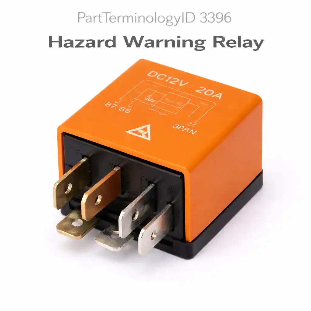
PartTerminologyID 3396, Hazard Warning Relay, is the relay that controls the four-way hazard flasher circuit, simultaneously flashing all four turn signal lamps and the instrument cluster hazard indicator at the regulated flash rate when the hazard switch is activated. Unlike the turn signal flasher, which operates only the left or right side lamps depending on the stalk position, the hazard warning relay flashes all four corners of the vehicle simultaneously and operates independently of the turn signal circuit and ignition state, remaining functional with the ignition off on most applications so the vehicle can signal a stopped or disabled condition without key-on power. The four attributes that determine correct fitment are the circuit architecture and whether the application uses a separate hazard relay and turn signal flasher or a combined unit that serves both functions; the flash rate load sensitivity and how the relay responds to bulb outages or LED bulb substitutions that reduce the circuit's total current draw below the relay's calibrated threshold; the activation source and ignition independence of the hazard circuit; and the instrument cluster indicator interaction that feeds the hazard warning light through the same relay contact as the lamp circuit on many applications.
What the Hazard Warning Relay Does
Four-way simultaneous flash circuit and ignition independence
The hazard warning relay activates when the hazard switch grounds the relay coil circuit, completing the coil activation path independently of the ignition switch state on most applications. This ignition independence is the feature that allows the hazard lights to operate when the vehicle is disabled and the ignition is off, which is the primary use case for the hazard system. The relay contact switches at a calibrated flash rate, typically between 60 and 120 flashes per minute as required by most regulatory standards, and routes battery power to all four turn signal lamp circuits simultaneously through the hazard wiring. The relay continues flashing until the hazard switch is deactivated or the battery is discharged.
Flash rate load sensitivity and bulb outage detection
Thermal and electronic flasher relays used in hazard warning circuits are typically load-sensitive, meaning the flash rate is determined by the total current draw of all lamps in the circuit. A standard incandescent turn signal bulb circuit draws a specific current range at which the relay is calibrated to flash at the correct rate. When a bulb fails and the total circuit current drops below the calibrated threshold, the flash rate increases noticeably, a behavior commonly called hyper-flashing, which serves as the driver warning that a bulb has failed. This load-sensitive behavior means the relay's correct function depends on the circuit maintaining its designed lamp load. When one or more incandescent bulbs are replaced with LED bulbs that draw substantially less current than the incandescent originals, the relay sees a reduced load and hyper-flashes even with all lamps functional. An LED-compatible flasher relay with an electronic timer that flashes at a fixed rate independent of circuit current is required to restore correct flash rate when any LED turn signal or hazard lamp substitution is made.
Separate hazard relay versus combined turn signal and hazard unit
Many applications from the late 1970s through the early 2000s used two separate flasher units: a turn signal flasher that operated only the directional lamps and a hazard flasher that operated all four lamps when the hazard switch was activated. On these applications, a turn signal that flashes correctly but hazard lights that do not flash, or flash at the wrong rate, indicates a hazard relay fault rather than a turn signal flasher fault. Ordering the turn signal flasher when the hazard relay has failed, or vice versa, produces no improvement because the two units serve separate circuits. On more recent applications with BCM-integrated lighting control, neither a separate hazard relay nor a turn signal flasher may be present as a discrete replaceable component, and the flash function is managed entirely within the BCM software. Listings must identify whether the application uses separate units or a combined unit, and must note BCM-integrated applications where no discrete relay replacement is applicable.
Instrument cluster hazard indicator interaction
The instrument cluster hazard warning indicator typically flashes in synchronization with the lamp circuit on most applications. On relay-controlled architectures, the indicator lamp circuit is often wired in parallel with the lamp circuit through the relay contact, meaning the cluster indicator receives the same switched power as the exterior lamps. A hazard relay that flashes the exterior lamps correctly but produces no cluster indicator flash has a fault in the indicator circuit branch rather than in the main lamp switching contact. On BCM-controlled applications, the cluster indicator is driven by the BCM independently of the exterior lamp circuit, and a BCM output fault can produce an absent cluster indicator while the exterior lamps continue to flash correctly.
Top Return Scenarios
Scenario 1: "Hazard lights do not flash at all when hazard switch is activated"
The relay coil is not being activated or the relay contact has failed open. Test for hazard switch ground signal at the relay coil terminal when the hazard switch is pressed. A correct ground signal present at the coil with no relay output indicates a relay coil or contact failure. No ground signal at the coil when the switch is pressed indicates a hazard switch contact fault or a broken wire between the switch and relay coil terminal. On BCM-controlled applications, the BCM may be failing to output the flasher control signal, and the BCM output must be tested before the relay is condemned.
Prevention language: "Test for hazard switch activation signal at the relay coil terminal before replacing the relay on a no-flash complaint. No activation signal at the coil with the switch pressed indicates a switch or wiring fault. Activation signal present with no relay output confirms a relay coil or contact failure."
Scenario 2: "Hazard lights flash too fast after installing LED turn signal bulbs"
The LED bulbs draw substantially less current than the incandescent bulbs they replaced, reducing the total circuit load below the thermal flasher relay's calibrated threshold. The relay is functioning correctly and responding to the reduced load as designed by increasing flash rate. This is not a relay fault. The correct resolution is replacing the thermal flasher relay with an LED-compatible electronic flasher relay that flashes at a fixed rate independent of circuit current load. Installing a load resistor in parallel with each LED bulb to restore the original current draw is an alternative but generates heat and reduces the efficiency benefit of the LED substitution.
Prevention language: "Hyper-flashing after LED bulb installation is not a relay fault. The thermal flasher relay is responding correctly to the reduced LED current draw. Replace the thermal flasher with an LED-compatible electronic flasher relay rated for the application's socket and terminal configuration to restore correct flash rate with LED bulbs."
Scenario 3: "Turn signals work but hazard lights do not flash"
On applications with separate turn signal and hazard flasher units, the hazard relay has failed while the turn signal flasher remains functional. The two circuits share the turn signal lamp wiring but use separate relay units. Replacing the turn signal flasher produces no improvement because the hazard circuit uses the dedicated hazard relay. The hazard relay must be identified separately from the turn signal flasher and ordered under PartTerminologyID 3396 rather than the turn signal flasher PartTerminologyID.
Prevention language: "On applications with separate hazard and turn signal flasher units, functional turn signals with non-functional hazard lights indicates a hazard relay fault, not a turn signal flasher fault. Confirm your application uses separate units before ordering. The hazard relay and turn signal flasher are different components with different PartTerminologyIDs."
Scenario 4: "Hazard lights flash but cluster indicator does not flash"
The relay contact is functioning correctly and flashing the exterior lamps, but the cluster indicator circuit has a fault. On relay-controlled indicator circuits, the indicator lamp branch from the relay output has an open circuit or a failed indicator bulb. On BCM-controlled indicator circuits, the BCM is not outputting the indicator flash signal despite receiving the correct exterior lamp feedback. Neither fault requires relay replacement. The relay is functioning correctly, and the diagnosis should proceed to the indicator circuit wiring or the BCM indicator output.
Listing Requirements
PartTerminologyID: 3396
circuit: four-way simultaneous flash, ignition-independent (mandatory)
flash rate load sensitivity and LED hyper-flash explanation (mandatory)
separate vs. combined hazard and turn signal unit identification (mandatory)
BCM-integrated application note where no discrete relay is present (mandatory)
LED-compatible variant availability where applicable (mandatory)
OEM part number cross-reference (mandatory)
FAQ (Buyer Language)
Is the hazard relay the same as the turn signal flasher?
On some applications they are the same physical unit. On others they are separate components. Check your vehicle's fuse and relay box diagram to confirm whether one combined unit or two separate units serve your application. If your vehicle has two separate flasher positions, one is for the turn signals and one is for the hazard circuit. Replacing the wrong one will produce no improvement. PartTerminologyID 3396 covers the hazard warning relay specifically; the turn signal flasher is covered under a separate PartTerminologyID.
My hazard lights work but my turn signals do not. Is this the right relay?
No. If hazard lights function correctly but turn signals do not, the turn signal flasher has failed on applications with separate units, or the turn signal stalk switch has failed. The hazard relay is functioning correctly if the hazard circuit flashes all four lamps. Diagnosis should proceed to the turn signal flasher or stalk switch rather than the hazard relay.
Can I use a higher-rated flasher relay to make my hazards flash brighter or faster?
The flash rate on a load-sensitive thermal relay is determined by the circuit's current draw, not by the relay's current rating. Installing a higher-rated relay does not change flash rate or brightness. A relay with a different load sensitivity calibration will flash at a different rate than the OEM relay for the same lamp load. For correct flash rate, the replacement relay must match the OEM unit's load sensitivity specification, not just its current rating and terminal configuration.
What Sellers Get Wrong About PartTerminologyID 3396
The most common listing error is failing to distinguish the hazard relay from the turn signal flasher. Listings that describe a generic flasher relay without specifying which circuit it serves generate orders from buyers whose application uses separate units and who need the hazard-specific relay, not the turn signal flasher. Every listing under PartTerminologyID 3396 must identify the four-way hazard circuit as the specific application and must note whether the listed relay is compatible with the turn signal circuit as well or serves the hazard circuit exclusively.
The second most common error is omitting the LED hyper-flash note. LED turn signal and hazard bulb substitutions are among the most common DIY lighting modifications, and buyers who install LED bulbs and then observe hyper-flashing frequently conclude the relay has failed when it is functioning correctly. A listing that explains load sensitivity and directs LED users to an electronic fixed-rate flasher relay prevents the return of a correctly functioning thermal relay from a buyer who installed LED bulbs and misattributed the hyper-flash response to a relay fault.
The third error is omitting the BCM-integrated application note. Buyers on BCM-controlled lighting platforms who search for a hazard relay and order a discrete relay unit will find no relay socket to install it in, generating a return that could have been prevented with a single sentence noting that some applications integrate the hazard function in the BCM with no separate replaceable relay.
Cross-Sell Logic
Turn Signal Flasher: on applications with separate units, a turn-signals-only failure while hazards work indicates the turn signal flasher has failed; listings for 3396 should cross-reference the turn signal flasher PartTerminologyID for buyers whose symptom points to the turn signal circuit
LED-Compatible Electronic Flasher: the correct resolution for hyper-flashing after LED bulb installation; should be offered as an alternative in listings where the standard thermal relay is listed, particularly for applications with common LED lighting upgrades
Hazard Warning Switch: a hazard switch with failed contacts produces no coil activation signal and no flash on either circuit; should be tested when the relay coil receives no activation signal with the switch pressed
BCM: on BCM-controlled applications, hazard flash function loss that cannot be resolved with relay replacement indicates a BCM output fault or BCM software fault requiring module testing or reprogramming
Final Take for PartTerminologyID 3396
Hazard Warning Relay (PartTerminologyID 3396) is the four-way flasher relay where circuit identification, load sensitivity explanation, LED hyper-flash guidance, and separate-versus-combined unit clarification are the four listing attributes that prevent the highest volume of wrong-diagnosis and wrong-component returns in the flasher relay category. The LED hyper-flash note and the separate-versus-combined unit clarification together address the two most common buyer misconceptions about flasher relay operation: that hyper-flashing after an LED upgrade means the relay has failed, and that the hazard relay and turn signal flasher are always the same component. Sellers who include all four attributes in every listing under PartTerminologyID 3396 give buyers the complete picture of how the hazard circuit operates, what its failure looks like, and what the correct resolution is for each symptom pattern before the part is ordered.