Fuel Injection Main Relay (PartTerminologyID 3312): Where Ignition-Switched Supply, ECM Self-Hold Circuit, and Prime Cycle Behavior Determine Correct No-Start Diagnosis and Fitment
Written by Arthur Simitian | PartsAdvisory
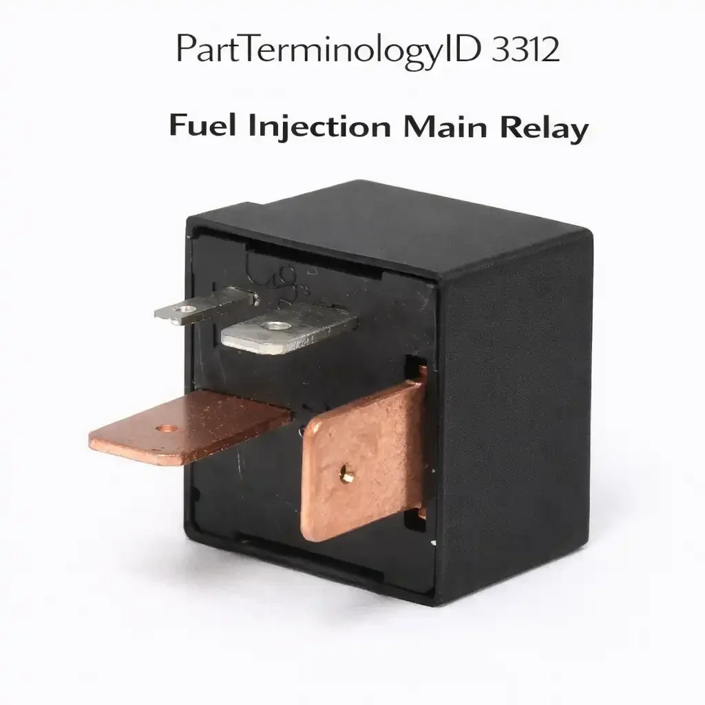
PartTerminologyID 3312, Fuel Injection Main Relay, is the relay that supplies primary switched power to the fuel injection system, providing operating voltage to the ECM, the fuel injector power rail, the fuel pressure regulator, and related fuel system sensors and actuators when the ignition is switched on. It is one of the most consequential relays on the vehicle because its failure disables the entire fuel injection system simultaneously, producing a complete no-start condition with no injector pulse, no fuel pressure, and no ECM communication in some configurations. The three attributes that determine correct fitment and accurate diagnosis are the specific circuits the relay supplies power to; the ECM self-hold circuit that keeps the relay energized after ignition key release to allow the ECM to complete its shutdown sequence and preserve adaptive fuel trim data; and the fuel prime cycle behavior that distinguishes a relay fault from a fuel pump fault when no-start is the complaint.
The fuel injection main relay is among the most misdiagnosed components on early fuel-injected vehicles precisely because its failure mimics so many other fuel system faults. A technician who does not verify relay output voltage before testing injectors, checking fuel pressure, or condemning the ECM will spend diagnostic time on components that are functioning correctly while the relay fault goes untested. Listings that include relay output voltage test guidance before other fuel system diagnosis steps prevent the most expensive and time-consuming return scenarios for this PartTerminologyID.
What the Fuel Injection Main Relay Does
Ignition-switched power supply and controlled circuits
When the ignition key is switched to the on position, the ignition circuit energizes the fuel injection main relay coil, closing the relay contacts and supplying battery voltage to the fuel injection system's primary power distribution point. From this point, power is distributed to the ECM power input terminal, the fuel injector supply rail that powers all injector solenoids through the ECM driver circuit, the fuel pressure regulator solenoid on returnless systems, the mass airflow sensor and throttle position sensor supply circuits, and the idle air control valve on applications where it draws power from the fuel injection supply rather than from a dedicated ignition feed. The scope of the relay's controlled circuits means that a complete relay failure disables every one of these functions simultaneously, producing a no-start condition that appears to implicate multiple systems when the root cause is a single relay contact failure.
ECM self-hold circuit and post-ignition shutdown
On many applications, the fuel injection main relay is not de-energized immediately when the ignition key is switched off. Instead, the ECM holds the relay coil energized through an ECM output pin for a period of several seconds after the ignition is off, allowing the ECM to complete its shutdown sequence. During this post-ignition period, the ECM writes updated adaptive fuel trim values, closed-loop fuel correction factors, and diagnostic monitor results to non-volatile memory. A relay that de-energizes immediately when the ignition is switched off, without holding through the ECM self-hold circuit, causes the ECM to lose updated adaptive data on every shutdown. The symptom is a vehicle that runs well after a full drive cycle but returns to open-loop rich or lean operation on the next cold start because the learned corrections were not saved. This subtle symptom is rarely attributed to the relay because the vehicle does start and run, just with degraded fuel trim adaptation.
Heat-related intermittent failure and the hot no-start pattern
The fuel injection main relay on many Japanese domestic market vehicles from the mid-1980s through the late 1990s is located in the passenger compartment, mounted on the firewall or under the dashboard, where it is subject to elevated ambient temperatures when the engine is hot and the vehicle is stopped. The relay's internal solder joints, which connect the coil terminals and contact terminals to the relay's printed circuit board on some designs, are subject to thermal expansion and contraction cycling that eventually produces micro-fractures in the solder connections. These fractures cause the relay to fail open when hot, producing the classic hot no-start symptom: the vehicle starts and runs normally from cold, but after a hot soak of 20 to 45 minutes, the engine cranks without starting until the relay cools. This intermittent hot no-start pattern is a diagnostic signature of the fuel injection main relay on applications where it is known to exhibit this failure mode, and it is the primary symptom that should direct the diagnosis to the relay before any other fuel system component is tested.
Top Return Scenarios
Scenario 1: "Engine cranks but does not start from cold"
The relay contact set has failed open completely and is not supplying power to the fuel injection system. No injector pulse, no fuel prime, no ECM communication. The fault is straightforward but is frequently preceded by a diagnosis that tests the fuel pump, the ignition system, and the ECM before the relay output voltage is verified. Testing for voltage at the fuel injector supply rail with the ignition on and the engine not cranking takes less than 30 seconds and immediately identifies a relay fault before any other component is removed or tested.
Prevention language: "Before testing injectors, fuel pump, or ECM, verify voltage at the fuel injector supply rail with the ignition on. Zero voltage at the injector supply with a known-good ignition circuit confirms the fuel injection main relay has failed open. The relay is the correct first test on any fuel injection no-start diagnosis."
Scenario 2: "Hot no-start that clears after cooling"
The relay fails intermittently when hot due to thermal stress on internal solder connections. The vehicle starts normally from cold and after short hot soaks but fails to start after extended hot soaks of 20 minutes or more. The relay tests correctly when cold because the solder fractures close under cool temperatures. A relay that tests good at room temperature but fails when heated to operating temperature should be replaced based on the symptom pattern, not on cold resistance testing alone.
Prevention language: "Hot no-start that clears after 30 to 45 minutes of cooling is the diagnostic signature of a failing fuel injection main relay on this application. The relay may test correctly when cold. Replace the relay based on the hot no-start symptom pattern before testing other fuel system components."
Scenario 3: "Vehicle runs but fuel trim is consistently off after relay replacement"
The replacement relay does not support the ECM self-hold circuit correctly, either because it has a different coil resistance than the original or because the self-hold terminal is not connected in the replacement relay's pinout. The ECM loses adaptive fuel trim data on every shutdown and relearns from base fuel maps on each cold start, producing inconsistent fuel trim readings and slightly rough running until the adaptive learning cycle completes again during each drive.
Prevention language: "Verify the replacement relay supports the ECM self-hold circuit on applications where the ECM holds the relay coil after ignition off. A relay that de-energizes immediately when the ignition is switched off will cause the ECM to lose adaptive fuel trim data on every shutdown."
Listing Requirements
PartTerminologyID: 3312
controlled circuits: ECM supply, injector rail, sensors, idle control (mandatory)
ECM self-hold circuit note where applicable (mandatory)
hot no-start pattern note on known affected applications (mandatory)
injector supply voltage test as first diagnostic step (mandatory)
OEM part number cross-reference (mandatory)
FAQ (Buyer Language)
My car cranks but won't start and I have no injector pulse. Is this the relay?
It is the most likely cause. Switch the ignition on without cranking and test for battery voltage at the fuel injector wiring harness connector supply terminal. If no voltage is present and the ignition circuit is functioning, the fuel injection main relay is not supplying power to the injector rail. Replace the relay and retest before inspecting the ECM or injectors.
My car only fails to start when hot. It always starts when cold. What is happening?
This is the classic hot no-start pattern associated with fuel injection main relay thermal failure on Japanese domestic market applications. The relay's internal solder connections develop micro-fractures from heat cycling and open when the relay reaches operating temperature after a hot soak. The relay cools and the connections close again, allowing cold starts normally. Replace the relay based on this symptom pattern. The relay will test correctly when cold.
How is this different from the Fuel Injection Combination Relay (PartTerminologyID 3308)?
The combination relay (3308) contains two separate contact sets in one housing, typically combining fuel pump power and ECM or injector supply in a single assembly. The main relay (3312) is a single-contact-set relay that supplies the primary power distribution point for the fuel injection system. On some applications the functions overlap or one supersedes the other depending on model year. Check the relay diagram for your specific application to confirm which relay position your vehicle uses.
What Sellers Get Wrong About PartTerminologyID 3312
The most significant listing error is omitting the hot no-start symptom pattern note on applications where this failure mode is well documented. The hot no-start is the dominant complaint for the fuel injection main relay on many Japanese domestic market vehicles, and buyers who do not recognize the symptom pattern will test every other fuel system component before reaching the relay. Listing copy that calls out the hot no-start pattern by name and describes the 20 to 45 minute cooling period directs buyers to the correct diagnosis before unnecessary parts replacement occurs. The second error is failing to include the injector supply voltage test as the recommended first diagnostic step. Buyers who read "test injector supply voltage before removing the fuel pump" will spend 30 seconds confirming the relay fault instead of hours removing components that are working correctly. These two pieces of guidance eliminate the majority of return scenarios for this PartTerminologyID.
Cross-Sell Logic
Fuel Injection Combination Relay (PartTerminologyID 3308): the combination relay and main relay serve overlapping functions on some applications; both should be verified on any no-start diagnosis where the relay architecture is unclear
Fuel Injection Cold Start Relay (PartTerminologyID 3304): the cold start relay operates in the same fuel injection power supply sequence as the main relay and should be tested alongside it on cold-start-specific no-start complaints
Electric Fuel Pump Relay (PartTerminologyID 3304): on applications where the fuel pump relay is separate from the main relay, both should be verified when no-start is accompanied by zero fuel pressure
ECM Power Relay: on applications where the ECM has a dedicated power relay separate from the fuel injection main relay, both must be functioning for the ECM to initialize and command injection
Final Take for PartTerminologyID 3312
Fuel Injection Main Relay (PartTerminologyID 3312) is the single relay whose failure disables the entire fuel injection system simultaneously, making it the highest-priority diagnostic target on any fuel injection no-start complaint. The hot no-start symptom pattern, the injector supply voltage test as the first diagnostic step, and the ECM self-hold circuit note are the three listing attributes that determine whether buyers diagnose the relay correctly before removing and testing other fuel system components. Sellers who include the hot no-start pattern description, the 30-second injector supply voltage test guidance, and the self-hold circuit note in every fuel injection main relay listing give buyers the diagnostic tools to identify this relay as the fault source before the diagnosis becomes expensive and the return scenario becomes inevitable.