Fuel Injection Combination Relay (PartTerminologyID 3308): Where Combined Circuit Function, Internal Contact Isolation, and ECM Control Interaction Determine Correct Fuel Injection Relay Diagnosis
Written by Arthur Simitian | PartsAdvisory
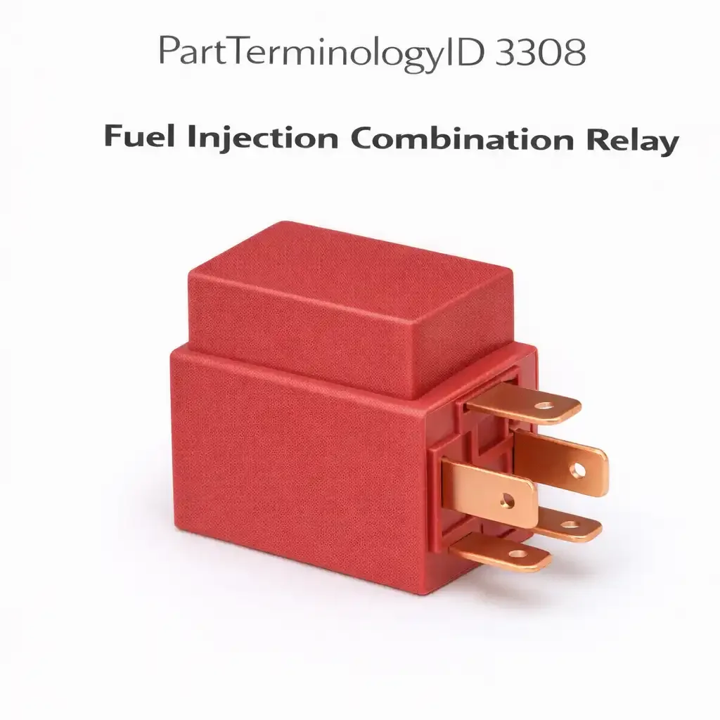
PartTerminologyID 3308, Fuel Injection Combination Relay, is a single relay assembly that contains two or more electrically isolated contact sets within one housing, serving multiple fuel injection system circuits simultaneously. The most common configuration combines the fuel pump power circuit and the fuel injector power supply circuit in a single relay body, allowing the ECM to control both circuits through a shared relay assembly while maintaining electrical isolation between the pump's high-current load and the injector driver circuit's lower-current supply. The three attributes that determine correct fitment are the specific circuit combination the relay controls; the contact current rating for each internal circuit, since the fuel pump circuit and injector circuit carry different current loads and require different contact ratings within the same relay body; and how the ECM activates the relay, either through a single shared coil that energizes both contact sets simultaneously or through two independent coil inputs that allow the ECM to sequence the circuits independently during startup.
What the Fuel Injection Combination Relay Does
Dual circuit architecture and contact isolation
The fuel injection combination relay's defining characteristic is the internal separation of two circuits within a single housing. On the most common configuration found on Japanese domestic market vehicles from the mid-1980s through the mid-2000s, the relay contains a main contact set that powers the ECM and fuel injector supply rail, and a separate contact set that powers the electric fuel pump. Both contact sets are energized by the same coil when the ignition is switched on, but they are electrically isolated from each other within the relay body. This isolation prevents the fuel pump's inrush current spike during startup from affecting the ECM power supply and injector driver circuits. A combination relay that has developed an internal short between the two contact sets will produce erratic fuel delivery behavior because the pump's current transients are now on the injector supply circuit.
ECM activation and prime cycle behavior
On most applications using the fuel injection combination relay, the ECM receives power through one contact set of the relay and controls the relay coil through an output pin, creating a self-holding circuit after initial ignition-key activation. During the fuel prime cycle, which typically lasts 2 to 3 seconds after the ignition is switched on before the engine is cranked, the ECM activates the relay to pressurize the fuel rail. If the combination relay's pump contact set fails open, the fuel prime cycle does not occur, the fuel rail does not pressurize before cranking, and the engine cranks without starting or starts briefly and stalls as the residual rail pressure is consumed. This no-start symptom is often misdiagnosed as a fuel pump failure before the relay is tested.
Top Return Scenarios
Scenario 1: "Engine cranks but does not start"
The fuel pump contact set within the combination relay has failed open. No fuel prime occurs, the rail does not pressurize, and the engine cranks without starting. The fuel pump itself is functional but receives no power because the relay contact is open. Testing fuel pressure at the rail during the prime cycle, before cranking, distinguishes a relay fault from a pump fault: zero pressure during prime with a functional pump indicates the relay is not supplying pump power.
Prevention language: "Test fuel rail pressure during the prime cycle before condemning the fuel pump. Switch the ignition on without cranking and verify rail pressure builds to specification within 2 to 3 seconds. Zero pressure during the prime cycle with a known-good pump indicates the pump contact set in the combination relay has failed open."
Scenario 2: "Engine starts but stalls immediately"
The ECM contact set in the combination relay has failed intermittently or has developed high contact resistance. The ECM loses power momentarily after initial startup, causing the engine to stall before it stabilizes at idle. The ECM may log a power supply fault or no fault at all depending on whether the loss was complete or a voltage drop. The stall symptom is frequently attributed to the idle air control valve or a fuel delivery fault before relay contact resistance is measured.
Prevention language: "If the engine starts and immediately stalls, test supply voltage at the ECM power input terminal with the engine running. A voltage reading below specification under load indicates contact resistance in the combination relay's ECM contact set rather than an idle or fuel delivery fault."
Listing Requirements
PartTerminologyID: 3308
circuit combination: fuel pump plus ECM supply, fuel pump plus injector supply, or other (mandatory)
contact current rating per circuit (mandatory)
coil configuration: single shared coil or dual independent coils (mandatory)
fuel prime cycle test note (mandatory)
OEM part number cross-reference (mandatory)
FAQ (Buyer Language)
How do I know if my combination relay has failed on the pump side or the ECM side?
Test fuel rail pressure during the prime cycle to check the pump contact set. Switch the ignition on without cranking and verify pressure builds within 2 to 3 seconds. Then test supply voltage at the ECM power terminal with the engine running to check the ECM contact set. A fault in either contact set produces a distinct symptom: failed pump contact produces no-start from no prime pressure; failed ECM contact produces stall or intermittent running from loss of ECM power.
Can I replace this with two separate relays?
On applications where the combination relay uses two independently activated coils, it is sometimes possible to substitute two separate standard relays if the relay socket can be adapted. However, the internal contact isolation that prevents pump current transients from affecting the ECM circuit is a design requirement, and any substitution must maintain that isolation. On applications using a single shared coil, substitution with two relays requires modifying the activation circuit, which is not recommended without a wiring diagram for the specific application.
What Sellers Get Wrong About PartTerminologyID 3308
The most common listing error is describing the fuel injection combination relay as a standard fuel pump relay without disclosing the combined circuit architecture. Buyers who replace the relay expecting to restore only fuel pump function may be surprised when ECM power or injector supply is also restored or interrupted, and may misattribute additional symptoms to other components. Every listing under PartTerminologyID 3308 must identify both circuits the relay controls and must specify the contact current rating for each circuit independently. The prime cycle test note is the single most important diagnostic guidance for this relay because it separates relay fault from pump fault for the most common no-start presentation.
Cross-Sell Logic
Electric Fuel Pump Relay (PartTerminologyID 3304): on applications where the combination relay is superseded by separate fuel pump and injector relays, both components should be verified together
Fuel Injection Main Relay (PartTerminologyID 3312): the main relay and combination relay share the fuel injection power supply circuit on some applications; both must be tested when no-start is the complaint
Electric Fuel Pump: a failed combination relay pump contact is frequently misdiagnosed as pump failure; the relay should be tested before pump replacement on any no-prime no-start diagnosis
Final Take for PartTerminologyID 3308
Fuel Injection Combination Relay (PartTerminologyID 3308) is the dual-circuit fuel system relay where combined circuit identification, per-circuit contact current rating, and fuel prime cycle test guidance are the three listing attributes that prevent the most damaging return scenarios. The prime cycle test is the diagnostic step that separates relay fault from pump fault in the no-start presentation, and listings that include this test guidance save buyers from unnecessary pump replacement before the relay is properly evaluated. Sellers who identify both controlled circuits, specify contact ratings, and include the prime cycle test note in every combination relay listing give buyers the information needed to diagnose correctly and order confidently.