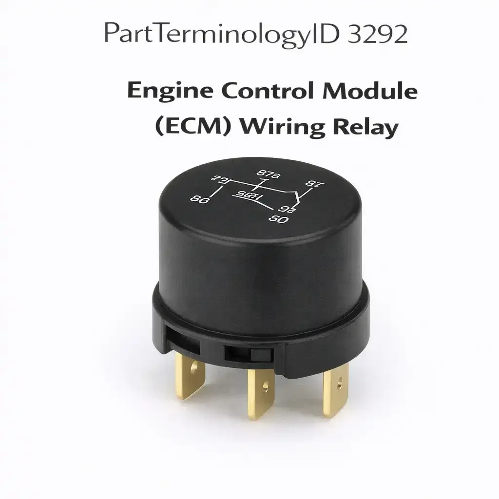
Engine Control Module (ECM) Wiring Relay (PartTerminologyID 3292): Where ECM Harness Power Distribution, Contact Resistance, and Supply Circuit Identification Determine Correct Diagnosis
Written by Arthur Simitian | PartsAdvisory
PartTerminologyID 3292, Engine Control Module (ECM) Wiring Relay, is the relay that distributes switched ignition power through the ECM wiring harness to the ECM's sensor supply circuits, actuator power circuits, and reference voltage outputs. It is distinct from the ECM Power Relay (PartTerminologyID 3312) in that the wiring relay supplies the ECM's peripheral harness circuits rather than the ECM module's primary power input terminal. The three attributes that determine correct fitment are the specific harness circuits the relay powers within the ECM wiring architecture; the contact resistance specification, since the ECM's sensor reference voltages and actuator power outputs require stable, low-resistance supply to maintain calibration accuracy; and the differentiation from the ECM power relay on applications where both relays are present in the same relay center and carry similar part numbers.
What the ECM Wiring Relay Does
Harness power distribution and sensor reference supply
The ECM wiring relay supplies switched ignition power to the ECM wiring harness branch that carries sensor excitation voltage and actuator solenoid power. On applications where this relay is present, the ECM receives its primary module power through a separate relay, while the wiring relay independently controls power to the mass airflow sensor, throttle position sensor, manifold absolute pressure sensor, and idle air control solenoid through the harness power distribution circuit. A failed wiring relay that is stuck open removes supply voltage from all sensors and actuators on the harness branch simultaneously, producing multiple sensor fault codes and a rich or lean running condition from loss of sensor inputs. This multi-sensor fault pattern is the diagnostic signature of the ECM wiring relay fault rather than individual sensor failures.
Contact resistance and sensor reference voltage accuracy
Sensor reference voltages on most applications are calibrated at 5.00 volts from the ECM's internal reference regulator. The ECM wiring relay supplies the upstream power that the ECM's internal reference regulator uses to generate this 5-volt output. A relay with degraded contacts and elevated resistance introduces a voltage drop in the supply that reduces the available headroom for the ECM's internal regulator. The regulator compensates initially, but when contact resistance reduces supply voltage below the regulator's dropout threshold, the 5-volt reference output drops and all sensors receiving this reference produce shifted readings. The ECM interprets the shifted sensor voltages as out-of-range readings and logs multiple simultaneous sensor fault codes. The multi-code pattern resolves when supply voltage is restored by relay replacement.
Top Return Scenario
Scenario 1: "Multiple sensor codes with no single sensor fault identified"
The ECM wiring relay has failed or developed high contact resistance, reducing supply voltage to the harness branch below the ECM's reference regulator threshold. The ECM logs simultaneous fault codes for MAF, TPS, MAP, and IAC circuits because all sensors on the wiring harness branch are receiving degraded reference voltage. Each sensor tests correctly in isolation when bench-tested or when supplied from a known-good voltage source, but all produce out-of-range readings in the vehicle because the harness supply voltage is degraded at the relay contact.
Prevention language: "Multiple simultaneous sensor fault codes that do not resolve with individual sensor replacement indicate a supply voltage fault upstream of the sensors. Test voltage at the ECM wiring harness power supply terminal with the ignition on. A reading below specification under load confirms contact resistance in the ECM wiring relay rather than individual sensor failures."
Listing Requirements
PartTerminologyID: 3292
controlled circuits: sensor supply, actuator power, or reference voltage branch (mandatory)
differentiation from ECM Power Relay (PartTerminologyID 3312) (mandatory)
multi-sensor fault code pattern as diagnostic indicator (mandatory)
harness supply voltage test under load (recommended)
OEM part number cross-reference (mandatory)
FAQ (Buyer Language)
How is the ECM wiring relay different from the ECM power relay?
The ECM power relay (PartTerminologyID 3312) supplies the primary operating voltage to the ECM module itself. The ECM wiring relay (PartTerminologyID 3292) supplies power to the peripheral circuits in the ECM wiring harness, including sensor excitation and actuator solenoid power. On some applications both relays are present and both must be functioning for the ECM to receive module power and for its sensors and actuators to receive harness supply voltage.
What Sellers Get Wrong About PartTerminologyID 3292
The most common listing error is describing the ECM wiring relay as equivalent to the ECM power relay without distinguishing the harness circuit function from the module power function. Buyers who order this relay expecting it to restore ECM module power on a dead-ECM no-start complaint may install it correctly and find no improvement because the ECM module power relay is the fault on their application. Every listing under PartTerminologyID 3292 must state that this relay supplies the ECM harness peripheral circuits and must direct buyers to confirm which relay in their application serves the harness power function versus the module power function before ordering.
Cross-Sell Logic
ECM Power Relay (Fuel Injection Main Relay, PartTerminologyID 3312): the module power relay and the wiring relay are both required for full ECM system operation on applications where both are present
Mass Airflow Sensor: multi-sensor fault codes from a degraded ECM wiring relay are frequently misdiagnosed as MAF sensor failure; the relay should be tested first when multiple sensor codes appear simultaneously
Throttle Position Sensor: simultaneous TPS and MAP faults alongside MAF faults indicate upstream supply fault rather than individual sensor failures
Final Take for PartTerminologyID 3292
Engine Control Module (ECM) Wiring Relay (PartTerminologyID 3292) is the ECM harness power distribution relay where controlled circuit identification, differentiation from the ECM power relay, and multi-sensor fault code pattern recognition are the three listing attributes that prevent the most common misdiagnosis scenarios. The multi-sensor fault code pattern is the diagnostic signature of this relay's failure and the single most useful piece of buyer guidance, because it directs buyers to test the upstream supply relay before replacing individual sensors that are all showing faults from the same root cause. Sellers who identify the harness supply function, differentiate from PartTerminologyID 3312, and include the multi-sensor code pattern note give buyers the context to diagnose correctly before ordering.