Early Fuel Evaporation (EFE) Control Relay (PartTerminologyID 3288): Where Heater Grid vs Exhaust Heat Valve Architecture and Coolant Temperature Threshold Determine Cold-Start Driveability Fitment
Written by Arthur Simitian | PartsAdvisory
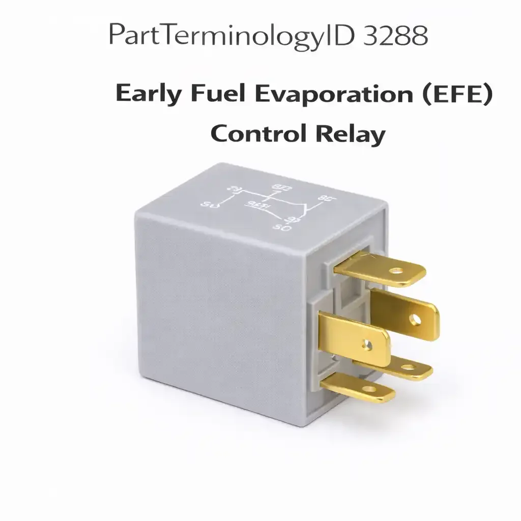
PartTerminologyID 3288, Early Fuel Evaporation (EFE) Relay, is the relay that controls the early fuel evaporation system during cold engine warm-up, heating the intake manifold floor or floor-mounted heater grid to improve fuel vaporization before the engine reaches normal operating temperature. That definition identifies the EFE relay's cold-start driveability function and leaves unresolved the three attributes that determine whether a replacement restores correct EFE operation: which EFE system architecture the relay serves, whether it powers an electrically-heated intake manifold grid or controls the vacuum solenoid that actuates a thermostatic exhaust heat control valve directing exhaust gases under the intake manifold; the coolant temperature threshold at which the ECM or temperature switch de-energizes the relay and shuts off the EFE heat source after warm-up; and the narrow carbureted engine application window for this component, since EFE systems were designed specifically for carbureted and early throttle body injection engines and are not present on port fuel injection or modern engine management systems.
What the EFE Relay Does
Heater grid versus exhaust heat valve architectures
The electric heater grid EFE system uses a resistive heating element mounted in the intake manifold below the carburetor base, drawing 12 to 20 amperes during the warm-up phase to heat the manifold floor and improve fuel droplet vaporization in the incoming air-fuel charge. The relay powers this grid element directly, and the high current load requires a relay contact rated for at least 20 amperes continuous operation. The exhaust heat valve EFE system uses a thermostatic valve in the exhaust crossover passage that, when closed, routes hot exhaust gases through the intake manifold heat riser passage. The relay in this architecture powers a vacuum control solenoid that opens or closes the heat valve, not the heat source itself. The solenoid current draw is 0.2 to 0.5 amperes, far below the heater grid current. Substituting a heater grid relay in a vacuum solenoid application provides a higher contact rating than needed but functions correctly. Substituting a solenoid-rated relay in a heater grid application provides insufficient contact current rating and the relay contacts overheat and fail rapidly.
Coolant temperature de-activation threshold
The EFE relay is active only during cold engine operation, typically until coolant temperature reaches 60 to 80 degrees Celsius. At this point, the ECM or a coolant temperature switch opens the relay activation circuit and the EFE heat source is de-energized, preventing over-heating of the intake charge during normal operating temperature. A relay replacement on a system where the coolant temperature switch or ECM activation output has failed will result in the EFE system being permanently inactive regardless of the relay's condition. Buyers who report that the replacement relay did not fix their cold-start hesitation symptom should be directed to test the coolant temperature switch or ECM activation signal at the relay coil terminal before concluding the relay is defective.
Carbureted and TBI application window
EFE systems are present on carbureted domestic engines from approximately 1975 through 1987 and on early throttle body injection engines from approximately 1980 through 1992. Port fuel injection systems from the mid-1980s onward do not use EFE heater grids or exhaust heat valves because fuel is injected directly into the intake port and cold-start driveability is managed through fuel enrichment and ignition timing strategies rather than intake manifold heating. Listings under PartTerminologyID 3288 have a well-defined legacy application window, and fitment claims that extend into port fuel injection engines are incorrect. Every application in the fitment range must be confirmed as a carbureted or throttle body injection application before the listing is published.
Top Return Scenarios
Scenario 1: "Cold-start hesitation not resolved after relay replacement"
The replacement relay is correctly installed but the coolant temperature switch that activates the relay coil has failed open. The relay receives no activation signal during cold-start operation. The EFE system does not heat the intake manifold regardless of the relay's condition.
Prevention language: "Before replacing the EFE relay, confirm the coolant temperature switch provides an activation signal to the relay coil terminal when the engine is cold. If no activation signal is present during cold operation, the temperature switch is the failed component. Test the relay coil terminal voltage during cold start before ordering this relay."
Scenario 2: "Heater grid relay burns out within one season on solenoid application"
The buyer installed a standard ISO relay rated for 20 amperes on an application requiring a solenoid-rated low-current relay. The over-specified relay functions correctly. This scenario is the benign direction. The reverse, installing a low-current solenoid relay on a heater grid application, results in contact failure from overload within the first cold season.
Prevention language: "EFE system type: [heater grid / exhaust heat valve solenoid]. Heater grid applications require a relay rated for [X] amperes continuous. Exhaust heat valve applications use a low-current vacuum solenoid and a standard relay is adequate. Confirm your application type before specifying the replacement relay contact rating."
Scenario 3: "Vehicle is fuel-injected, no EFE relay socket found"
The buyer's vehicle has a port fuel injection system installed from the factory or converted from carburetion. No EFE relay socket exists in the relay center. EFE systems were not used on port fuel injection engines.
Prevention language: "EFE relay applications: carbureted and throttle body injection engines only, approximately 1975-1992. Port fuel injection engines do not use EFE systems. Confirm your engine uses a carburetor or throttle body before ordering."
Listing Requirements
PartTerminologyID: 3288
EFE system architecture: heater grid or exhaust heat valve solenoid (mandatory)
contact current rating for heater grid applications (mandatory)
coolant temperature activation pre-check note (mandatory)
application window: carbureted and TBI only (mandatory)
OEM part number cross-reference (mandatory)
Catalog Checklist for ACES/PIES Teams
PartTerminologyID = 3288
require EFE architecture type in every listing (mandatory)
require contact current rating for heater grid applications (mandatory)
require application window confirmation: carbureted and TBI only (mandatory)
prevent fitment claims on port fuel injection engines
require coolant temperature switch pre-check note (mandatory)
differentiate from EGR Relay (PartTerminologyID 3284): EGR relay controls exhaust gas recirculation; EFE relay controls intake manifold heating for cold-start driveability; both may be in the same relay center but serve different emissions and driveability functions
FAQ (Buyer Language)
My carbureted engine stumbles on cold starts. Is the EFE relay the problem?
Cold-start stumble on carbureted engines has several causes before the EFE relay. Confirm that the choke is operating correctly and closing fully on cold start. Confirm that the accelerator pump is delivering a shot of fuel on initial throttle tip-in. Confirm that the coolant temperature switch is sending an activation signal to the EFE relay coil terminal when the engine is cold. Only after eliminating these more common causes should the EFE relay be considered as the fault. A failed EFE relay that prevents intake manifold heating during cold-start produces rough idle and stumble on initial throttle application, specifically during the first two to five minutes of operation from cold.
What happens if I leave the EFE relay bypassed?
Bypassing or removing the EFE relay permanently disables the intake manifold heating function. On carbureted engines in cold climates, this results in rough cold-start driveability, fuel condensation on cold manifold walls, and potential stumble and stall during the first minutes of operation. In warm climates where ambient temperatures rarely drop below 15 degrees Celsius, the effect may be minimal. The EFE system was designed to compensate for cold-weather driveability limitations in carbureted fuel delivery, and its absence is most noticeable in cold-weather operation.
How do I know if my vehicle uses a heater grid or exhaust heat valve EFE system?
Check under the carburetor base. If you see a flat metal grid element between the carburetor mounting flange and the intake manifold, connected by two wires, the system uses an electric heater grid. If you see a vacuum hose running to a heat control valve on the exhaust crossover passage near the manifold, the system uses an exhaust heat valve. Some applications use both, with the electric grid for initial heating and the exhaust heat valve for sustained warm-up heating.
What Sellers Get Wrong About PartTerminologyID 3288
The most common error is listing the EFE relay without specifying the EFE system architecture type. The heater grid and exhaust heat valve systems use relays with very different contact current ratings, and the contact rating mismatch in the heater grid direction causes rapid relay failure from overload. A listing that does not identify the architecture forces buyers to guess which relay type they need, and buyers who guess incorrectly in the heater grid direction will install a relay that fails before the end of the first cold season. The architecture type is the first specification that must appear in every EFE relay listing.
The second error is failing to confirm the carbureted application window before publishing fitment claims. The EFE system has a well-defined end-of-production date that aligns closely with the transition from carburetion to port fuel injection on most domestic platforms. General Motors made this transition progressively from 1985 through 1991. Ford made the transition on most passenger car platforms by 1988. Chrysler completed the transition by 1992 on most applications. Fitment claims that extend past these transition points for specific platforms generate returns from buyers with fuel-injected engines who find no EFE system installed on their vehicles.
Application Range and Fitment Guidance for PartTerminologyID 3288
The EFE relay application range is one of the most clearly bounded of any relay PartTerminologyID because the function it serves, intake manifold heating for carbureted cold-start driveability, became obsolete with the adoption of port fuel injection. The earliest applications date from approximately 1975 when federal emissions regulations prompted General Motors to introduce the EFE system as a cold-start driveability aid on their carbureted V8 and V6 engines. Ford introduced a similar system under different nomenclature on their EEC-equipped engines beginning in the late 1970s. Chrysler used lean-burn carbureted systems with thermostatic heat valve controls that serve the same function through a somewhat different control architecture. All three domestic manufacturers had transitioned the majority of their light-duty vehicle lineups to port fuel injection by 1992, effectively ending new EFE relay applications at that point for domestic platforms.
Cross-Sell Logic
Coolant Temperature Switch: the activation control for the EFE relay; a failed temperature switch prevents EFE operation regardless of relay condition and is the most common cause of EFE inactivity
EGR Valve Control Relay (PartTerminologyID 3284): often shares the relay center with the EFE relay on the same application; buyers diagnosing carbureted engine cold-start issues may need to address both systems
Carburetor: for cold-start stumble on carbureted engines where EFE relay replacement does not resolve the driveability issue; choke function and accelerator pump condition are the more common cold-start fault sources
Final Take for PartTerminologyID 3288
Early Fuel Evaporation (EFE) Relay (PartTerminologyID 3288) is the legacy cold-start relay where EFE architecture type, contact current rating for heater grid applications, and carbureted application window confirmation are the three listing attributes that prevent the return scenarios specific to this narrow-application component. The application window is strictly bounded by the end of carburetor production on each platform. The architecture type determines the contact rating requirement. The coolant temperature switch pre-check note prevents relay replacement on systems where the temperature switch is the actual fault. Sellers who specify all three eliminate the misdiagnosis returns and the out-of-window returns that together account for the majority of EFE relay returns in this category.
EFE Relay Diagnostic Sequence
For buyers approaching the EFE relay from a cold-start driveability complaint, the correct diagnostic sequence before ordering the relay is as follows. First, confirm the engine actually uses an EFE system by checking for a heater grid element under the carburetor base or a vacuum-controlled heat valve on the exhaust crossover passage. Second, with the engine cold, test for activation voltage at the relay coil terminal immediately after the ignition is turned to the run position. If activation voltage is absent with the engine cold, the coolant temperature switch or thermostatic switch is open and is the failed component, not the relay. Third, if activation voltage is present at the coil terminal but the heater grid or solenoid does not receive power at its connector, test the relay contacts by substitution or bench test. A relay that receives coil activation voltage but does not pass contact current to the load is failed. Fourth, if both coil activation voltage and contact output voltage are present at the heater element or solenoid connector, the relay is functioning correctly and the fault is in the load circuit, the heater element, or the vacuum solenoid itself. Following this four-step sequence before ordering eliminates relay replacement on the majority of EFE systems where the relay is functional and the fault is in the activation circuit or the load.