Exhaust Gas Recirculation (EGR) Valve Control Relay (PartTerminologyID 3284): Where Actuator Type Identification, ECM Driver Compatibility, and Fault Code Diagnosis Determine Correct EGR Relay Fitment
Written by Arthur Simitian | PartsAdvisory
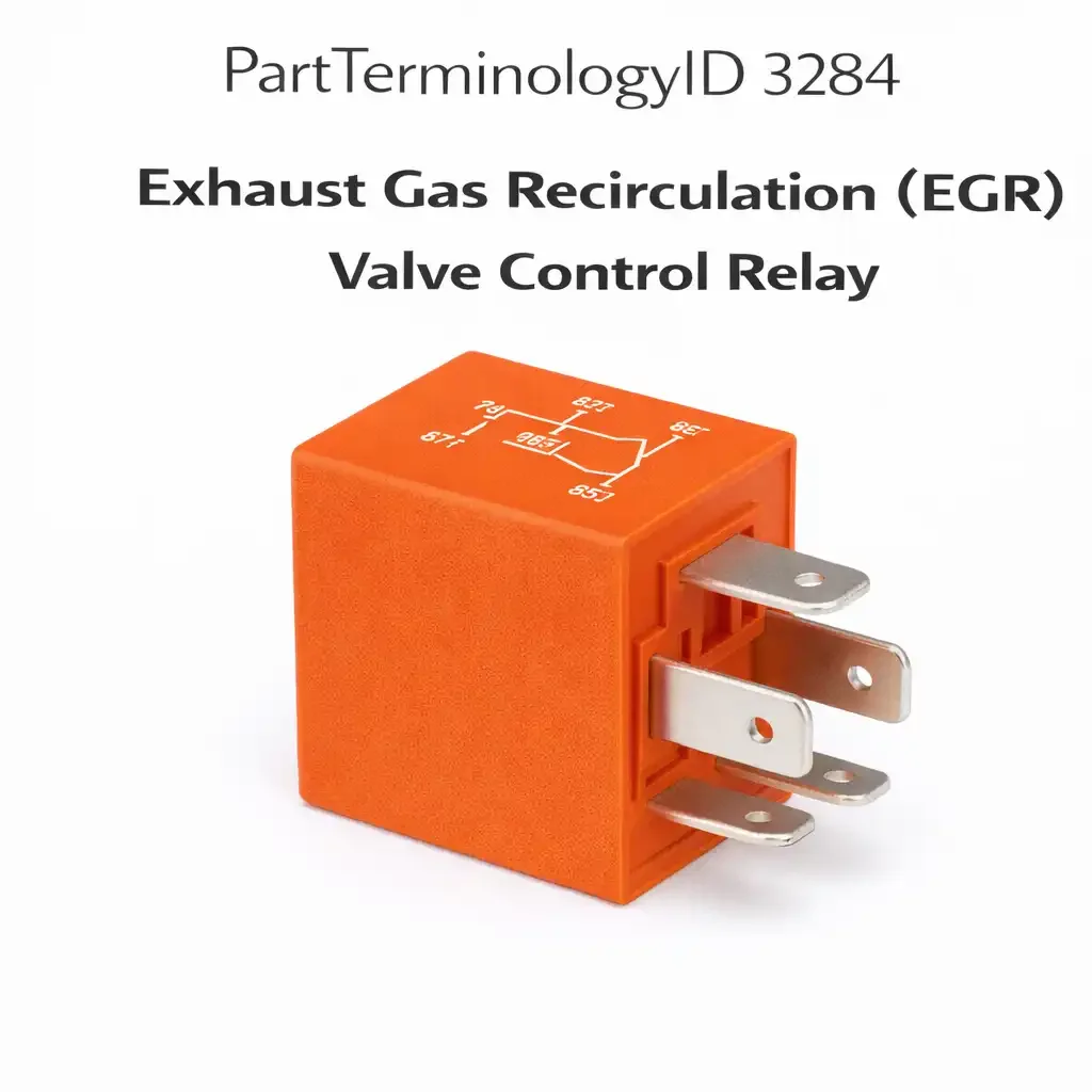
PartTerminologyID 3284, Exhaust Gas Recirculation (EGR) Valve Control Relay, is the relay that controls power delivery to the EGR valve actuator, enabling the ECM to operate the EGR system by switching the power circuit to the valve solenoid or motor. That definition identifies the EGR relay's power switching function and leaves unresolved the three attributes that determine whether a replacement restores correct EGR operation: whether the EGR valve uses a vacuum solenoid actuator that the relay powers with a simple on/off signal, or an electronic stepper motor or DC motor actuator that the relay powers as part of a more complex position-control circuit; whether the relay coil circuit is driven directly by the ECM's output driver, which imposes a specific coil resistance tolerance to protect the driver circuit; and whether the EGR system fault that prompted the relay replacement has been properly diagnosed through fault code retrieval rather than assumed to be a relay failure based on EGR-related symptoms alone.
What the EGR Valve Control Relay Does
Vacuum solenoid versus electronic actuator architecture
EGR valve control relay applications divide primarily between two actuator architectures. The vacuum solenoid architecture, used on most domestic and import vehicles from the mid-1970s through the mid-1990s, uses the relay to switch power to a vacuum control solenoid that opens and closes the EGR valve by modulating manifold vacuum applied to the valve diaphragm. The relay in this architecture is a simple on/off power switch for the solenoid coil. The solenoid coil resistance is typically 20 to 60 ohms, drawing 0.2 to 0.6 amperes at 12 volts, which is a very low current load that does not impose significant contact stress on the relay. Electronic motor actuator architectures, used on most platforms from the mid-1990s onward, use a stepper motor or DC motor to position the EGR valve directly without vacuum assistance. The relay in these architectures may switch higher motor currents, particularly during initial valve movement from the closed position, and the contact rating must be verified against the motor's stall current rather than its steady-state operating current.
ECM driver circuit compatibility and coil resistance tolerance
On applications where the ECM drives the EGR relay coil directly through an output driver transistor, the relay coil resistance must fall within the tolerance the ECM driver circuit expects. ECM output drivers are typically designed for a specific coil resistance range, and a relay with a coil resistance significantly outside this range may cause the ECM driver to operate at incorrect current levels. A relay with too-low coil resistance will draw more current than the driver expects, potentially triggering ECM driver protection mode and logging a false EGR circuit fault code. A relay with too-high coil resistance will draw less current than required for reliable coil pull-in at low battery voltage conditions, causing intermittent EGR operation during cold weather or when the battery voltage is marginally low.
Fault code diagnosis before relay replacement
EGR-related fault codes, particularly P0400 (EGR flow insufficient) and P0401 (EGR flow insufficient detected), are almost never caused by relay failure alone. These codes are generated when the ECM commands EGR flow and does not detect the expected change in manifold pressure or EGR position sensor feedback. The relay is one potential failure point in a chain that includes the EGR valve itself, the position sensor, the vacuum supply if applicable, the vacuum solenoid, and the wiring. Replacing the relay without retrieving and analyzing the fault codes, and without testing the relay coil activation signal at the relay terminal before replacement, risks replacing a functional relay on a system whose actual fault is in the EGR valve, sensor, or wiring.
Top Return Scenarios
Scenario 1: "EGR fault code persists after relay replacement"
The relay was replaced based on an EGR fault code without confirming the relay was the failed component. The replacement relay is functional, but the fault code persists because the EGR valve itself is stuck closed with carbon deposits, or the EGR position sensor is failed and reporting incorrect position to the ECM. The relay was not the cause of the fault code.
Prevention language: "EGR fault codes are not caused exclusively by relay failure. Before replacing this relay, retrieve the specific fault code and confirm the relay coil activation signal is present at the relay terminal when the ECM commands EGR operation. A relay that receives no activation signal is not the failed component."
Scenario 2: "Wrong coil resistance, ECM logs circuit fault after relay replacement"
The replacement relay has a coil resistance of 60 ohms but the application requires 85 ohms. The ECM driver current is higher than expected, causing the driver protection circuit to log a relay circuit fault code on the first drive cycle after installation.
Prevention language: "Coil resistance: [X] ohms. This relay is specified for direct ECM driver output. The coil resistance must match the specified value within [X] ohms. Substituting a relay with a different coil resistance may cause the ECM to log a circuit fault code on the driver output."
Listing Requirements
PartTerminologyID: 3284
actuator type: vacuum solenoid or electronic motor (mandatory)
ECM driver coil resistance specification (mandatory for ECM-driven coil applications)
fault code diagnosis note before relay replacement (mandatory)
contact current rating for motor actuator applications (mandatory)
OEM part number cross-reference (mandatory)
Catalog Checklist for ACES/PIES Teams
PartTerminologyID = 3284
require actuator type identification in every listing (mandatory)
require ECM coil resistance specification where applicable (mandatory)
require fault code pre-check note (mandatory)
prevent relay replacement recommendation without fault code confirmation note
differentiate from EGR valve: the relay controls power to the valve actuator; the valve itself is the mechanical component that recirculates exhaust gas and is not included in this PartTerminologyID
require OEM part number cross-reference (mandatory)
FAQ (Buyer Language)
I have a P0401 code. Is the EGR relay the problem?
P0401 indicates insufficient EGR flow, which is most commonly caused by a clogged EGR valve or EGR passages rather than a relay fault. The relay should be tested by confirming the coil activation signal is present at the relay terminal when the ECM commands EGR operation. If the signal is present and the relay does not respond, the relay is failed. If the signal is absent, the fault is in the ECM output or the wiring. If the relay is functioning correctly and the EGR flow is still insufficient, the EGR valve or passages require inspection and cleaning or replacement.
My EGR relay gets hot to the touch. Is this normal?
Slight warmth is normal for a relay under load, but if the relay is too hot to touch comfortably during normal engine operation, the contact resistance has increased from wear or contamination, causing higher-than-normal resistive heating. A relay that runs excessively hot is near the end of its service life and should be replaced before it fails open and disables the EGR system entirely.
Can I disable the EGR system by removing the relay?
Removing the EGR relay disables the EGR system and will cause the ECM to log an EGR fault code and illuminate the check engine light on OBD-II compliant vehicles. On emissions-tested vehicles, this will result in a failed emissions test. Disabling the EGR system is not a recommended repair strategy and in most jurisdictions constitutes tampering with emissions control equipment.
What Sellers Get Wrong About PartTerminologyID 3284
The most common error is listing the EGR valve control relay as the first diagnostic step for any EGR fault code. The EGR relay is one of the least common failure points in the EGR system. Carbon deposits in the EGR valve and passages, failed EGR position sensors, and cracked or collapsed vacuum hoses are far more common causes of EGR fault codes than relay failure. A listing that does not include the diagnostic pre-check note sends buyers through a relay replacement on a system whose relay is functioning correctly, generating a high-confidence return of a functional component. The fault code diagnosis note is not optional courtesy content. It is the single most effective return prevention measure for this listing.
The second error is omitting the coil resistance specification on ECM-driver applications. The ECM driver circuit for the EGR relay coil is a precision output that operates at specific current levels. A relay with incorrect coil resistance disrupts this current calibration and causes the ECM to log driver circuit faults that the buyer will incorrectly attribute to the replacement relay being defective. Providing the coil resistance specification and noting the tolerance range allows buyers to verify the replacement before installation and prevents the return scenario where a correctly installed relay causes new fault codes that the buyer attributes to the replacement.
Cross-Sell Logic
EGR Valve: the most common cause of EGR system faults; carbon deposits in the valve and passages are far more likely than relay failure to cause P0400 and P0401 codes
EGR Vacuum Solenoid: for vacuum-controlled EGR applications where the solenoid controls vacuum application to the valve and may fail independently of the relay
Early Fuel Evaporation Relay (PartTerminologyID 3288): for vehicles where both EGR and EFE systems share a common relay center location and may be confused during diagnosis
Final Take for PartTerminologyID 3284
Exhaust Gas Recirculation (EGR) Valve Control Relay (PartTerminologyID 3284) is the emissions system relay where actuator type identification, ECM coil resistance specification, and fault code diagnosis guidance are the three listing attributes that prevent the most common return scenario in this category: a buyer who replaced a functional relay because an EGR fault code pointed to the general EGR circuit without confirming that the relay specifically was the failed component. The EGR relay is rarely the cause of EGR fault codes. The listing copy that communicates this clearly and directs buyers to confirm the relay coil activation signal before purchasing saves both the buyer's time and the seller's return handling cost. Sellers who include the diagnostic pre-check note in every EGR relay listing reduce returns on this PartTerminologyID to near zero from the most common misdiagnosis scenario.
Application Range and Fitment Guidance for PartTerminologyID 3284
EGR valve control relay applications are present on most domestic and import vehicles equipped with EGR systems from approximately 1975 through the present, though the relay architecture varies significantly across this range. Vacuum-solenoid EGR systems from 1975 through approximately 1995 on most platforms use a simple relay to power the vacuum control solenoid. The relay in these applications is a standard ISO relay with a low-current contact rating adequate for the solenoid load. Electronic EGR actuator systems from approximately 1990 onward, beginning with Japanese manufacturer platforms and later adopted by domestic manufacturers, use motor-driven EGR valves with higher current requirements that mandate relay contact ratings above the standard 20-ampere ISO relay in some configurations. Diesel EGR systems introduced progressively from the mid-1990s onward use higher-current actuators with more demanding relay specifications than gasoline EGR applications in the same era.
The fitment range for EGR valve control relay applications must be carefully segmented by actuator type because a listing that groups vacuum solenoid and electronic motor applications under the same relay part number will provide incorrect hardware to one of the two application types regardless of which relay is shipped. Vacuum solenoid applications need a low-current relay with adequate coil resistance for ECM driver compatibility. Electronic motor applications may need a higher current contact relay with additional protection against motor back-EMF on the coil circuit. These requirements are mutually exclusive at the component level and require separate listings for the two actuator types within the same model year range if both actuator types appear within the claimed fitment range.
What Sellers Get Wrong About PartTerminologyID 3284 (Extended)
A third error specific to this PartTerminologyID is failing to note the back-EMF protection requirement for ECM-driven EGR relay coil circuits. When the ECM de-energizes the EGR relay coil by turning off its output driver transistor, the collapsing magnetic field in the coil generates a voltage spike that can exceed 100 volts in an unsuppressed coil. ECM output driver transistors for relay coil circuits typically include a flyback diode or transient voltage suppressor to clamp this spike. However, the suppressor is calibrated for the coil inductance of the OEM relay. A replacement relay with significantly different coil inductance generates a different flyback magnitude. If the replacement relay's flyback exceeds the ECM suppressor's clamping capability, progressive damage to the ECM output driver transistor accumulates over multiple EGR activation cycles, eventually causing ECM driver failure that appears as an intermittent EGR fault before becoming permanent. The coil inductance specification or the back-EMF suppression requirement must be confirmed when substituting relay hardware on ECM-driven coil circuits in emissions control applications.