Dual Battery Solenoid Relay (PartTerminologyID 3280): Where Isolation Solenoid Current Rating, Latching Architecture, and Voltage Sensing Threshold Determine Correct Dual Battery Fitment
Written by Arthur Simitian | PartsAdvisory
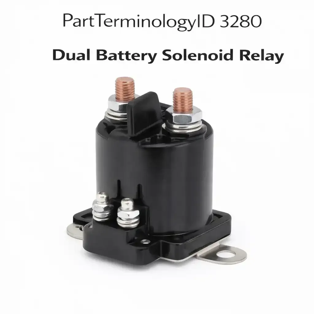
PartTerminologyID 3280, Dual Battery Solenoid Relay, is the high-current solenoid relay that connects and isolates the primary and secondary batteries in a dual battery electrical system, allowing the alternator to charge both batteries when the engine is running while preventing the secondary battery from discharging the primary starting battery when the engine is off. That definition correctly identifies the dual battery solenoid relay's isolation function and leaves unresolved the three attributes that determine whether a replacement maintains correct dual battery management: the continuous current rating of the solenoid contacts, which must handle the full alternator charging current passing between the two battery banks during charging; whether the solenoid uses a latching or non-latching architecture; and the voltage sensing threshold at which the solenoid connects and disconnects the battery banks based on detected charging voltage.
What the Dual Battery Solenoid Relay Does
Battery isolation during engine-off operation
The primary function of the dual battery solenoid relay is to isolate the secondary battery from the primary battery when the engine is off, ensuring that loads connected to the secondary battery, such as refrigerators, inverters, winches, or camping equipment, do not discharge the primary battery below the engine cranking threshold. When the solenoid is open, the two battery banks are electrically separate and a fully discharged secondary battery cannot affect the primary battery's state of charge. When the solenoid is closed, both batteries are in parallel and the alternator charges both simultaneously. The transition between these two states is the core function of the solenoid relay, and the transition threshold must be calibrated to match the vehicle's alternator output voltage and the desired battery management behavior.
Latching versus non-latching solenoid architecture
Non-latching solenoids require continuous coil current to maintain the closed state. They connect the battery banks when the coil receives voltage from the ignition or from a voltage sensing circuit, and they open immediately when the coil signal is removed. This architecture is simple and reliable but draws continuous coil current during the entire period the solenoid is closed, which represents a small but continuous parasitic load on the charging system. Latching solenoids use a pulse signal to change state and require no continuous coil current to maintain their position. A brief pulse closes the solenoid and it remains closed until a second brief pulse opens it. This architecture eliminates the continuous coil current draw but requires a more complex control circuit to generate the open and close pulses at the correct times. Substituting a non-latching solenoid in a latching solenoid application, or vice versa, will result in incorrect isolation behavior because the control circuit generates the wrong signal type for the solenoid type installed.
Voltage sensing threshold and alternator output compatibility
Voltage-sensing dual battery solenoids close when they detect a voltage above a calibrated threshold on the primary battery terminal, typically 13.3 to 13.8 volts, indicating that the alternator is charging. They open when the voltage drops below a second threshold, typically 12.7 to 12.9 volts, indicating that the engine has stopped and the alternator is no longer producing charging voltage. The sensing thresholds must be compatible with the vehicle's alternator output voltage range. A vehicle with a high-output alternator that maintains 14.8 volts under load may need a solenoid with a higher connection threshold to prevent premature disconnection during high-load alternator operation. A vehicle with a low-output alternator that struggles to exceed 13.5 volts under load may not reliably close a solenoid with a 13.8-volt connection threshold.
Top Return Scenarios
Scenario 1: "Secondary battery still drains primary after solenoid replacement"
The replacement solenoid contacts are not fully opening on engine shutdown due to a failed solenoid return spring or stuck contacts. The batteries remain connected after engine off, allowing the secondary battery loads to drain the primary battery. Alternatively, the voltage sensing threshold is set too low and the solenoid is not opening when the alternator stops producing charging voltage.
Prevention language: "After installation, verify battery isolation by measuring voltage on both battery terminals 30 minutes after engine shutdown. Both batteries should show independent resting voltage with no equalizing current flow. If the primary battery voltage drops toward the secondary battery's state of charge after engine off, the solenoid is not fully isolating the batteries."
Scenario 2: "Latching solenoid replaced with non-latching, batteries never connect"
The vehicle uses a latching solenoid controlled by brief open and close pulses from a battery management module. A non-latching solenoid was installed as a replacement. The non-latching solenoid requires continuous coil current to stay closed, but the control module only generates brief pulses. The solenoid clicks once on the close pulse and immediately opens again because the pulse ends before the solenoid can be held closed.
Prevention language: "Solenoid architecture: [latching / non-latching]. This application uses a [architecture] solenoid. Latching and non-latching solenoids are not interchangeable. Verify the replacement matches the original architecture type before installation."
Listing Requirements
PartTerminologyID: 3280
continuous contact current rating in amperes (mandatory)
solenoid architecture: latching or non-latching (mandatory)
voltage sensing threshold: connection and disconnection voltages (mandatory)
post-installation isolation verification note (mandatory)
OEM part number cross-reference (mandatory)
Catalog Checklist for ACES/PIES Teams
PartTerminologyID = 3280
require continuous contact current rating (mandatory)
require latching versus non-latching architecture disclosure (mandatory)
require voltage sensing threshold specification (mandatory)
prevent latching/non-latching substitution by explicitly noting incompatibility in listing
differentiate from Auxiliary Battery Relay (PartTerminologyID 3056): the auxiliary battery relay is a standard relay-format component; the dual battery solenoid relay is a high-current solenoid-format component for dedicated dual battery management architectures
require post-installation verification note (mandatory)
FAQ (Buyer Language)
What is the difference between a dual battery solenoid relay and a standard battery relay?
A standard battery relay uses a small electromagnetic coil to switch a set of contacts, typically rated to 30 to 80 amperes. A dual battery solenoid relay is a larger, heavier-duty component designed for continuous high-current operation between two battery banks, typically rated to 100 to 500 amperes. The solenoid format provides lower contact resistance and higher current capability than a standard relay format for the same physical envelope.
My winch drains my starting battery. Will a dual battery solenoid relay fix this?
If the winch is connected to the secondary battery and the solenoid relay is functioning correctly, the winch should draw from the secondary battery without affecting the primary starting battery. If the winch is connected directly to the primary battery and there is no secondary battery system, a dual battery solenoid relay installation is a longer project than replacing a failed relay. Confirm which battery the winch is connected to before diagnosing the solenoid relay.
How do I know if my dual battery solenoid relay has failed open or failed closed?
With the engine off, measure voltage on both battery terminals. If both show the same voltage immediately and that voltage equalizes to a common value within a few minutes of engine shutdown, the solenoid is failed closed and the batteries are continuously connected. If the engine is running and the secondary battery voltage does not rise above its resting voltage during a charging period where the primary battery is clearly being charged, the solenoid is failed open and charging current is not reaching the secondary battery.
What Sellers Get Wrong About PartTerminologyID 3280
The most common error is listing the dual battery solenoid relay without specifying the continuous current rating. Unlike standard relays where a 30-ampere or 40-ampere contact is generally adequate for most automotive load switching, dual battery solenoid relays must handle the full alternator output current passing through the inter-battery connection during charging. A high-output alternator on a diesel truck may produce 160 to 200 amperes. All of this current passes through the solenoid relay contacts during charging. A solenoid rated for 100 amperes in a 200-ampere alternator application will overheat progressively and fail within one or two seasons. The current rating must be verified against the alternator output specification for every application in the fitment range.
The second error is failing to specify the latching versus non-latching architecture. These two architectures are not visually distinguishable from the outside of the solenoid housing on many aftermarket products, and a buyer who orders the wrong architecture will install a solenoid that either continuously draws coil current or never maintains its closed state, depending on the direction of the substitution. The architecture type must be in the listing title or first specification line so that buyers can verify it matches their application before ordering.
Cross-Sell Logic
Auxiliary Battery Relay (PartTerminologyID 3056): for standard relay-format auxiliary battery management applications distinct from high-current solenoid-format dual battery systems
Battery: for buyers whose secondary battery has been fully discharged due to a solenoid relay failure that allowed continuous drain; the battery should be load-tested after a discharge event
Battery Management Module: for applications where a dedicated module controls the latching solenoid via pulse signals; a failed module prevents correct solenoid operation even with a new solenoid
Final Take for PartTerminologyID 3280
Dual Battery Solenoid Relay (PartTerminologyID 3280) is the high-current isolation component where continuous contact current rating, latching architecture type, and voltage sensing threshold are the three specifications that prevent the two most consequential replacement errors: installing an undersized solenoid that overheats under charging current, and installing the wrong architecture type that fails to maintain isolation or connection correctly. Both errors produce delayed failures that arrive after installation appears successful, making them more difficult to diagnose and more damaging to seller reputation than immediate fitment returns. Every listing must specify all three attributes. Sellers who do provide complete specification data for this component eliminate the delayed-discovery returns that define the failure pattern for dual battery solenoid relay listings.
Application Range and Fitment Guidance for PartTerminologyID 3280
OEM dual battery solenoid relay applications are concentrated on commercial and fleet vehicles, emergency service vehicles, and recreational vehicles where the secondary battery powers equipment loads independent of the starting system. Domestic full-size trucks with factory auxiliary battery provisions, typically on police interceptor, ambulance conversion, and upfitter packages, represent the largest OEM application base in the North American market. Some domestic pickup trucks from approximately 1995 onward offered factory dual battery options on diesel and heavy-duty packages, with the isolation solenoid installed in the engine bay near the battery tray. These OEM applications have established part number cross-references and relay center locations. Aftermarket dual battery installations on overlanding vehicles, off-road trucks, and marine vessels represent a larger market segment by volume but are outside the OEM fitment data scope.
The voltage sensing threshold is a critical specification that varies across platforms and regions. Vehicles operated in cold climates with battery heater systems or vehicles with high-output alternators may have charging systems that maintain voltage profiles outside the standard 13.3 to 13.8 volt connection threshold range. A solenoid with a fixed 13.5-volt connection threshold installed on a vehicle whose alternator output peaks at 13.3 volts under full electrical load will intermittently fail to connect the battery banks when demand is high and alternator output is below the connection threshold. This symptom appears as inconsistent secondary battery charging that is difficult to diagnose without understanding the relationship between the connection threshold and the alternator output voltage under load. Every fitment specification for this PartTerminologyID should include confirmation that the voltage sensing thresholds are compatible with the vehicle's alternator output range under all expected load conditions.
What Sellers Get Wrong About PartTerminologyID 3280 (Extended)
A third error specific to this PartTerminologyID is failing to address the contact resistance specification alongside the current rating. Contact resistance in a solenoid relay that carries 150 amperes continuously translates directly into resistive heating at the contact interface. A solenoid with 1 milliohm contact resistance passing 150 amperes generates 22.5 watts of heat at the contacts continuously. A solenoid with 5 milliohm contact resistance at the same current generates 112.5 watts. The difference in contact resistance between a new solenoid and a worn solenoid, or between a quality solenoid and an economy solenoid, can be the difference between a component that runs cool and lasts for years and one that runs hot and fails within a season. Contact resistance specification at rated current should be included in listings for high-current solenoid applications where thermal performance determines service life.
Dual Battery Solenoid Verification After Installation
After installing a replacement dual battery solenoid relay, a complete functional verification requires confirming both the isolation state and the connection state. For isolation verification, start the test with the engine off and allow both batteries to reach their resting voltage after any recent charging or discharging activity, typically 30 minutes of engine-off rest. Measure voltage on both battery terminals. If both show independent resting voltages that differ by more than 0.1 volt and remain stable without converging over a 10-minute observation period, the solenoid is correctly isolating the two banks. For connection verification, start the engine and allow the charging system to reach operating voltage. Measure voltage on both battery terminals. Both should show charging voltage within 0.2 volts of each other, confirming the solenoid has connected the banks for simultaneous charging. If the secondary battery voltage does not rise above its resting voltage during the charging test, the solenoid is not closing and the voltage sensing threshold, the control circuit, or the solenoid coil circuit requires further diagnosis.