Cruise Control Relay (PartTerminologyID 3232): Where Circuit Function, Speed Signal Source, and Brake Cancel Input Compatibility Determine Whether the Replacement Restores Correct Cruise Engagement
Written by Arthur Simitian | PartsAdvisory
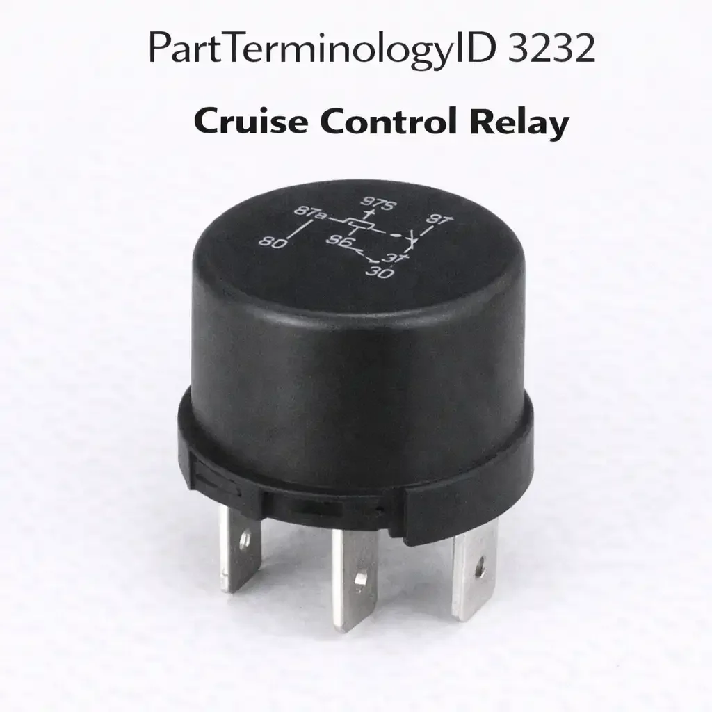
PartTerminologyID 3232, Cruise Control Relay, is the relay that controls power delivery to the cruise control module or actuator system, enabling the vehicle speed regulation function when engaged. That definition correctly identifies the cruise control relay's role in powering the system and leaves unresolved three attributes that determine whether a replacement actually restores correct cruise operation: which specific circuit function the relay serves within the cruise control architecture, whether it is the main power supply relay energizing the entire module, the engagement relay enabling the throttle actuator, or the cancel relay receiving input from the brake switch; the speed signal source compatibility required by the module this relay feeds; and the brake cancel input wiring configuration that must match for the cancel function to interrupt cruise engagement correctly on brake pedal application.
For sellers, the cruise control relay listing must also address the boundary between standalone electromechanical cruise systems from the 1980s and 1990s, where discrete relays are separately replaceable, and modern electronic cruise control systems integrated into the ECM or BCM, where the relay may be a standard ISO relay in the underhood relay center or may be integrated into the control module and not separately replaceable. Listings that omit this architectural distinction generate orders from buyers whose vehicles have module-integrated relay circuits that cannot be replaced as separate hardware.
What the Cruise Control Relay Does
Main power supply versus engagement relay functions
Cruise control relay applications split into two primary circuit functions. The main power supply relay energizes the cruise control module whenever the ignition is in the run position and the cruise master switch is active. This relay provides the continuous power rail that allows the module to monitor vehicle speed and respond to set, resume, and cancel commands. Loss of this relay results in a completely inoperative cruise system with no engagement response to any switch input. The engagement relay, by contrast, energizes only when the driver commands cruise engagement at the set speed and the module satisfies all enabling conditions including minimum speed threshold, brake release confirmation, and clutch release confirmation on manual transmission vehicles. Loss of the engagement relay allows the module to power up and respond to switch inputs but prevents actual throttle actuator engagement.
These two relay functions require separate listings under PartTerminologyID 3232 when both relays are present in the same vehicle's cruise control architecture. A listing that specifies only the year, make, and model without identifying which relay position is being supplied will send buyers a part that fits the relay center socket but serves the wrong circuit function. A buyer who needs the engagement relay receives the power supply relay, installs it, and finds the symptom unchanged. The return rate on cruise control relay listings without circuit function identification is predictably high because both relays in a dual-relay system often use identical housing and terminal configurations, making visual or dimensional verification impossible without function-specific documentation.
Speed signal source and module compatibility
The cruise control module served by the relay must match the speed signal source present on the vehicle. Standalone cruise control systems from the mid-1980s through the mid-1990s receive vehicle speed from a dedicated speedometer cable-driven speed transducer that generates a pulse signal proportional to driveshaft rotation. Systems from the late 1990s onward receive vehicle speed from the ABS wheel speed sensors through the ECM, or directly from the vehicle speed sensor on the transmission output shaft generating a digital pulse train. The relay that powers the module must be compatible with a module calibrated for the speed signal type present on the vehicle. A module-level mismatch caused by the wrong relay feeding the wrong module results in a system that powers up, accepts switch commands, and engages the throttle actuator, but immediately disengages or surges because the speed signal the module expects does not match the signal it is receiving.
Brake cancel input and safety circuit wiring
Cruise cancel on brake application is a safety function requiring a dedicated input from the brake light switch to the cruise control module or a separate cancel relay. Some architectures use a standalone cancel relay wired in series with the engagement circuit, so that brake pedal application energizes the cancel relay and interrupts the engagement circuit independently of the module's software cancel logic. This hardware cancel path operates even if the cruise control module fails to process the brake switch signal through its software input. The relay serving this cancel function has a different wiring configuration from the engagement relay, even if the housing is identical. Substituting the engagement relay for the cancel relay or vice versa creates a situation where one cancel path is present but the other is absent, which may pass initial testing but represents a safety-critical fitment error.
Top Return Scenarios
Scenario 1: "Cruise still does not engage after relay replacement"
The buyer replaced the main power supply relay but the engagement relay was the failed component. The cruise system powers up and responds to switch inputs but the throttle actuator never engages. Both relays in the system used the same ISO relay housing and pin configuration. The listing did not identify which relay position was supplied.
Prevention language: "Circuit function: [main power supply relay / engagement relay / cancel relay]. This listing supplies the [function] relay for the cruise control system. Verify the relay center position label on your vehicle before ordering. The power supply and engagement relays on this application use identical housings but serve different circuit functions."
Scenario 2: "Wrong relay, vehicle uses ECM-integrated cruise with no separate relay"
The buyer orders a standalone cruise control relay for a late-model vehicle where the cruise control function is fully integrated into the ECM with no separate relay. The relay center has no cruise control relay position. The delivered part cannot be installed.
Prevention language: "Architecture: standalone electromechanical cruise control with discrete relay [yes/no]. This part applies to vehicles with a dedicated cruise control relay in the underhood or interior fuse and relay center. Vehicles with ECM-integrated cruise control have no separate relay; the ECM module itself is the replacement path for cruise control faults on those applications."
Scenario 3: "Cruise engages but immediately disengages at speed"
The replacement relay restored power to an incorrect aftermarket cruise module. The module is calibrated for a cable-driven speed transducer but the vehicle uses an ABS-based speed signal. The system engages and immediately drops out because the speed signal type does not match the module's calibration. The relay is functioning correctly but powers an incompatible module.
Prevention language: "Speed signal type: [cable-driven transducer / transmission VSS / ABS-based ECM signal]. Confirm the cruise control module on your vehicle is calibrated for the same speed signal type before ordering. A relay that powers an incompatible module will allow engagement but cause immediate dropout or speed surge."
Scenario 4: "Cruise does not cancel on brake application"
The replacement supplied the engagement relay. The cancel relay, which serves a separate circuit that interrupts engagement on brake pedal application, was not included and was not identified as a separate relay in the listing. The engagement circuit functions correctly but the hardware cancel path is absent. Brake application cancels cruise through the module's software input only. The vehicle passes initial testing because software cancel works, but the hardware cancel path that operates independently of the module is not restored.
Prevention language: "Cancel relay: [included / sold separately as PartTerminologyID 3232 cancel relay position]. This listing covers the engagement relay only. The brake cancel relay is a separate component on this application and must be ordered separately if the cancel function is also faulted."
Listing Requirements
PartTerminologyID: 3232
circuit function: main power supply, engagement, or cancel relay (mandatory, in title or first line)
architecture: standalone electromechanical versus ECM-integrated (mandatory)
speed signal source compatibility (mandatory for standalone module applications)
brake cancel input wiring note (mandatory for cancel relay positions)
relay center position identifier or OEM relay label (strongly recommended)
OEM part number cross-reference (mandatory)
Catalog Checklist for ACES/PIES Teams
PartTerminologyID = 3232
require circuit function identification in every listing (mandatory)
require architecture type disclosure: standalone relay versus ECM-integrated (mandatory)
prevent listing on ECM-integrated cruise applications where no standalone relay socket exists
require speed signal source note for standalone module applications (mandatory)
require brake cancel relay differentiation when both engagement and cancel relays use the same housing (mandatory)
require OEM relay position label or relay center diagram reference (strongly recommended)
differentiate from Cruise Control Switch Relay (PartTerminologyID 3236): the switch relay serves the driver command input circuit; this relay serves the power supply or actuator circuit
FAQ (Buyer Language)
How do I know if my vehicle uses a standalone cruise control relay or ECM-integrated cruise?
Check your underhood or interior fuse and relay center diagram for a relay position labeled cruise control, cruise main, or cruise engage. If no such position appears, the cruise function is integrated into the ECM or BCM and does not use a separately replaceable relay. On those vehicles, a module-level diagnostic is the appropriate path before ordering any relay hardware.
My cruise control stopped working. Is the relay the first thing to replace?
No. The relay is a low-cost component to check but it is not the most common failure point. Before replacing the relay, confirm that the cruise master switch and the set, resume, and cancel switches provide correct signals. Confirm that the brake light switch functions correctly and the vehicle speed signal is clean and within specification. A relay failure that prevents cruise operation entirely is relatively uncommon compared to switch and sensor faults.
Can I use a generic ISO relay instead of the OEM cruise control relay?
Only if the circuit uses a standard ISO relay configuration with matching coil resistance, contact current rating, and pin layout. Some cruise control relay positions use non-standard relay configurations or relays with integrated diode suppression for the coil circuit. Substituting a standard ISO relay without diode suppression in a position that requires it can cause ECM driver circuit damage over time due to back-EMF on the coil de-energization spike.
Why does my cruise engage but not hold speed?
Relay replacement will not resolve a speed regulation fault. Speed hold problems are caused by actuator cable slack, throttle body issues, speed signal dropouts, or module calibration faults. The relay's function is binary: it either energizes the system or it does not. It does not affect speed regulation once the system is engaged.
What is the difference between the cruise control relay and the cruise control switch relay?
The cruise control relay (PartTerminologyID 3232) powers the actuator or module. The cruise control switch relay (PartTerminologyID 3236) serves the driver command input circuit, processing set, resume, and cancel switch signals. Both may be present in the same system. A fault in the switch relay prevents command inputs from reaching the module but may allow the module to power up. A fault in the main cruise relay prevents the module from powering up at all.
What Sellers Get Wrong About PartTerminologyID 3232
The most common error is listing the cruise control relay as a single undifferentiated component when the vehicle uses a dual-relay cruise control architecture with separate power supply and engagement relays. Both relays use standard ISO housings and pin configurations. Both appear in the same relay center. Without a circuit function label in the listing, buyers have no way to distinguish which relay they need. The symptom profile differs between the two relay positions, but buyers who have not diagnosed the system to the relay level will order based on year, make, and model alone and receive whichever relay the listing happens to supply. Returns are guaranteed when the system has two relay positions and the listing covers only one without identifying it.
The second error is listing cruise control relays for late-model vehicles without confirming that a standalone relay socket exists on that application. ECM-integrated cruise control has been standard on most domestic and import platforms since the early 2000s. A listing based on year and model ranges that extend into ECM-integrated applications will generate a steady stream of orders from buyers whose vehicles have no relay socket to receive the part. The relay center diagram for every application in the fitment range must be verified before publishing the listing.
The third error is omitting the brake cancel relay distinction. On vehicles with a separate hardware cancel relay, the cancel relay must be listed separately and the circuit function must be stated in both listings. Sellers who combine the engagement and cancel relay into a single listing without distinguishing the circuit functions ship the wrong part to buyers who specify their symptom as cruise not canceling on braking, which is the cancel relay's failure symptom, not the engagement relay's.
Cross-Sell Logic
Cruise Control Switch Relay (PartTerminologyID 3236): for buyers whose cruise command inputs are not processed correctly; the switch relay serves the driver input circuit and fails independently of the main cruise relay
Brake Light Switch: brake switch faults are the most common cause of cruise cancel failure and should be checked before the cancel relay is replaced
Vehicle Speed Sensor: for buyers whose cruise engages but cannot hold speed; VSS signal dropouts cause speed regulation loss without any relay failure
Application Range and Fitment Guidance for PartTerminologyID 3232
Standalone cruise control relay applications are concentrated in vehicles from approximately 1978 through 2005, with earlier applications using vacuum servo actuators and discrete relay-controlled power switching, and later applications using electronic throttle actuators with relay-switched power circuits. The relay architecture within this range varies significantly. Early domestic applications from 1978 through 1990 frequently use non-standard relay configurations that are vehicle-specific rather than ISO-standard. Applications from 1990 through 2005 largely standardized on ISO relay formats, making cross-platform fitment possible when the circuit function and current rating match. Applications after 2005 are predominantly ECM-integrated and carry no separately replaceable cruise relay in most platforms, though some truck and fleet applications retained standalone relay architectures through 2010.
Fitment ranges must be published at the trim level because cruise control was frequently an option rather than standard equipment, and the relay architecture differs between equipped and non-equipped trim lines within the same model year. A base-trim vehicle without the cruise option has no relay socket in the position labeled cruise control on the relay center diagram of the equipped trim. Publishing a fitment claim that includes base-trim non-equipped applications generates orders that cannot be satisfied because the relay socket simply does not exist on those vehicles.
Final Take for PartTerminologyID 3232
Cruise Control Relay (PartTerminologyID 3232) is the power management relay where circuit function identification, standalone versus ECM-integrated architecture, and brake cancel input compatibility are the three attributes that determine whether a replacement restores correct cruise engagement and cancel behavior. A listing that specifies only year, make, and model for a vehicle with dual relay cruise architecture ships the wrong relay to half the buyers who order it. A listing that does not confirm standalone relay architecture ships hardware to buyers whose vehicles have no socket for it. A listing that does not differentiate the cancel relay from the engagement relay leaves the safety-critical hardware cancel path unaddressed in every cancel-symptom diagnosis.
The cruise control relay is a low-cost component in absolute terms, but its failure modes and its position in a safety-relevant system make listing accuracy more consequential than the price suggests. A buyer who installs the wrong relay in the engagement position and believes the cruise system is repaired when it is not will discover the error at highway speed. A buyer who installs the wrong relay in the cancel position and believes the cancel function is restored when the hardware cancel path is still absent has a vehicle that relies entirely on software cancel logic. These are not abstract catalog errors. They are real-world outcomes of listings that treat the cruise control relay as an undifferentiated commodity part identified only by year and model.
Sellers who specify circuit function, architecture type, and cancel relay distinction in every cruise control relay listing eliminate the return scenarios that define this PartTerminologyID's failure pattern and provide buyers with the functional information they need to install the correct part the first time.
Application Range and Fitment Guidance for PartTerminologyID 3232 (Continued)
Domestic light-duty trucks represent the largest concentration of standalone cruise control relay applications extending into the 2000s because fleet and commercial operators specified cruise control on work trucks that retained electromechanical cruise systems longer than passenger car platforms. Ford F-series trucks from 1990 through 2002, General Motors full-size trucks from 1988 through 2004, and Chrysler full-size trucks from 1990 through 2001 all used standalone cruise relay architectures in varying configurations across this period. Within each of these ranges, the dual-relay architecture with separate power supply and engagement relays was common on higher-trim levels with more complex cruise control feature sets, while base trim applications sometimes used a single relay for both functions through a different contact switching arrangement.
Import applications in the same era present a more diverse relay architecture landscape. Japanese domestic market vehicles sold in North America frequently used manufacturer-specific relay configurations that do not cross-reference cleanly to the ISO relay standard. Toyota, Honda, Nissan, and Mitsubishi cruise control relay applications from 1985 through 1998 often use proprietary relay housings with non-standard terminal arrangements that must be matched by OEM part number rather than by functional specification. Aftermarket cross-references for these applications require confirmation against the OEM connector layout to ensure the terminal assignment matches, not just the physical housing dimensions. A relay that fits the socket but has its normally open and normally closed contacts assigned to different terminals than the OEM will invert the circuit function even if it appears to be a direct replacement from dimensional inspection.
European diesel cruise control applications from this era add another layer of complexity because vacuum servo actuators were used alongside and sometimes instead of electronic throttle actuators through 2000 on several platforms. The cruise relay on a vacuum actuator system controls power to the vacuum servo's solenoid valve assembly rather than to an electronic throttle controller. The solenoid valve current draw and the relay's contact current rating requirement on these applications differs from the electronic actuator applications, and substituting a relay rated for electronic actuator loads into a vacuum servo application, or vice versa, creates either an undersized or oversized contact for the actual load. Both directions of mismatch cause premature relay failure, with the undersized contact failing from overload and the oversized contact potentially failing from insufficient current to maintain contact wetting on the lower-current load.
What Sellers Get Wrong About PartTerminologyID 3232 (Extended)
A fourth error specific to this PartTerminologyID is failing to note the coil suppression requirement for cruise control relay coil circuits on ECM-controlled applications. On vehicles where the ECM directly drives the cruise relay coil, the relay coil circuit operates on the ECM's driver circuit, which has a maximum flyback voltage tolerance. Relay coils generate a flyback voltage spike on de-energization that can exceed 100 volts on an unsuppressed coil. ECM driver circuits for relay coils typically include internal suppression, but this suppression is calibrated for a relay coil with a specific inductance and resistance profile matching the OEM relay. A substitute relay with a significantly different coil inductance will generate a different flyback magnitude that may exceed the ECM driver's suppression capacity over time, causing gradual ECM driver circuit degradation that appears as an intermittent cruise fault before becoming a permanent one. The coil resistance specification must be checked and matched when substituting relay hardware on ECM-driven coil circuits.