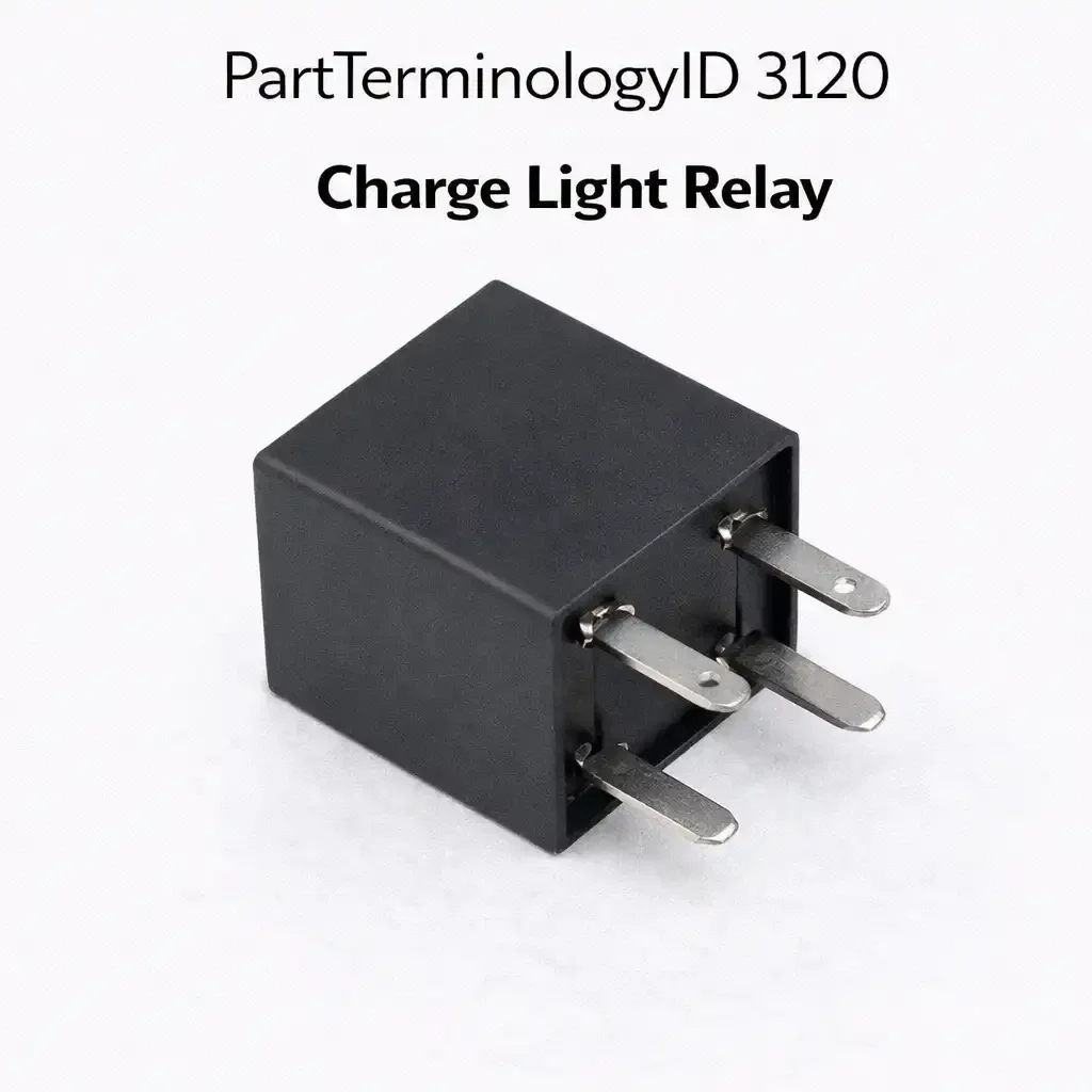
Charge Light Relay (PartTerminologyID 3120): Where Open Relay Failure Conceals Charging Faults and Alternator Diagnosis Prevents Unnecessary Relay Replacement
Written by Arthur Simitian | PartsAdvisory
PartTerminologyID 3120, Charge Light Relay, is the relay that controls the battery charge warning indicator lamp circuit, switching the lamp on when the alternator output voltage falls below the minimum charging threshold or when the charging system monitor detects a fault condition indicating the battery is not receiving adequate charge current. That definition covers the charge warning indicator circuit switching function correctly and leaves unresolved whether the relay switches the lamp supply circuit or the lamp ground circuit, the charging voltage threshold that triggers relay activation, whether the relay is activated directly by the voltage regulator's indicator output terminal or by a BCM output that processes the charging system voltage sensor signal, and whether a failed relay produces a permanently illuminated charge warning light, a charge warning light that never illuminates even during genuine charging failures, or no change in charge light behavior if the lamp circuit is connected independently of the relay on a parallel path.
For sellers, PartTerminologyID 3120 is the charging system warning relay where the open failure direction safety consequence, a relay that fails open prevents the charge warning lamp from illuminating during a genuine charging failure, is the primary safety disclosure. A driver whose alternator fails but whose charge light relay is also failed open has no electrical indication of the charging failure until the battery is depleted below the minimum operating voltage. The listing must frame the open failure safety consequence as the reason prompt relay replacement is required when the charge light relay is identified as failed.
What the Charge Light Relay Does
The charge light relay is typically held de-energized during normal alternator operation because the alternator's D+ terminal or the voltage regulator's lamp terminal provides a feedback voltage that balances the voltage across the indicator lamp circuit and prevents current flow through the lamp. When the alternator stops producing output, the feedback voltage collapses and the lamp circuit is completed through the relay, illuminating the charge warning light. This circuit topology means the relay's default state during normal operation is de-energized, and the failure mode that illuminates the light is the loss of the alternator feedback signal rather than the relay being commanded on by a control module.
A relay that has failed open in the lamp circuit prevents the lamp from completing its circuit even when the alternator feedback voltage collapses, eliminating the charge warning. A relay that has failed closed illuminates the charge light continuously regardless of alternator status. The continuously illuminated charge light is a less dangerous failure mode because it motivates the driver to investigate the charging system immediately, even though the charging system may be functioning normally. The dark-on-charging-failure mode is the dangerous failure because it provides no indication until battery depletion causes a no-start.
Alternator feedback topology and the relay circuit behavior
The charge light relay circuit on many older vehicles uses the alternator's D+ terminal feedback voltage to balance the lamp circuit and prevent current flow through the lamp during normal charging. When the ignition is on and the alternator is producing output voltage at the D+ terminal, the equal voltage on both sides of the lamp circuit prevents current from flowing and the lamp stays dark. When the alternator stops producing output, the D+ terminal voltage collapses and the voltage imbalance allows current to flow through the lamp, illuminating it. The relay in this architecture is part of the circuit that switches the lamp supply, not a separately commanded relay coil. A relay that fails in this circuit produces a different symptom depending on the failure direction: open contact prevents lamp illumination from any cause, including the alternator feedback collapse. Closed contact illuminates the lamp continuously regardless of alternator output because the supply current path is permanently completed.
Voltage regulator integration and standalone relay distinction
On some alternator designs the charge light relay circuit is integrated within the voltage regulator assembly rather than existing as a separate relay in the vehicle's fuse center. A buyer who searches the fuse center for a discrete charge light relay and finds no relay socket may have a vehicle where this function is performed by an internal voltage regulator circuit. Replacing the charge light relay in this case requires replacing the voltage regulator assembly rather than a discrete relay. Confirming whether the relay is external or internal to the alternator's voltage regulator prevents an unnecessary search for a relay socket that does not exist.
Charge light relay circuit and the alternator D+ feedback voltage
The charge warning lamp circuit in the relay era used a balanced voltage circuit where the alternator's D+ excitation terminal provided feedback voltage to one side of the lamp circuit during normal charging operation. This balanced voltage prevented current from flowing through the lamp and kept it dark. When the alternator stopped producing output, the D+ voltage collapsed and the unbalanced circuit allowed current to flow, illuminating the lamp. The relay's role was to switch the lamp supply circuit, but the balanced voltage feedback from the D+ terminal is what controlled whether the lamp actually illuminated once the relay was closed. A buyer who replaces the relay but does not understand the D+ feedback circuit may be confused when the lamp continues to illuminate after replacing the relay if the alternator's D+ terminal has also failed to produce excitation voltage. Both the relay and the D+ excitation circuit must be functional for the charge warning circuit to operate correctly.
Why This Part Generates Returns
Buyers return charge light relays because the charge light remains on after relay replacement because the alternator has actually failed and is not providing the feedback voltage that would extinguish the lamp, the charge light is permanently off after relay replacement because the replacement relay has a different circuit configuration that holds the lamp circuit open rather than allowing the alternator feedback topology to control it, and the relay is part of the voltage regulator assembly and cannot be replaced as a separate external component on this alternator design.
Status in New Databases
PIES/PCdb: PartTerminologyID 3120, Charge Light Relay
PIES 8.0 / PCdb 2.0: No change.
Listing Requirements
PartTerminologyID: 3120
lamp circuit switched: supply or ground (mandatory)
activation topology: voltage regulator feedback or BCM output (mandatory)
failure direction consequences: open relay conceals charging failures (mandatory)
alternator diagnosis note: confirm alternator is producing output before replacing relay (mandatory)
standalone versus voltage regulator integrated (mandatory)
OEM part number cross-reference (mandatory)
FAQ (Buyer Language)
Why is my charge light still on after I replaced the relay?
The alternator has likely failed and is not producing the feedback voltage that would extinguish the lamp. The charge light relay is functioning correctly by completing the lamp circuit in the absence of alternator feedback. Test the alternator output before returning the relay.
What happens if the charge light relay fails open?
The charge warning light cannot illuminate. If the alternator subsequently fails, the driver receives no warning until the battery is depleted below the minimum operating voltage. Replace a failed-open charge light relay promptly to restore charge warning visibility.
How do I confirm the alternator is the fault when the charge light stays on after relay replacement?
Measure voltage at the alternator output terminal with the engine running at approximately 2,000 RPM. A functioning alternator produces 13.8 to 14.4 volts at the output terminal. A voltage reading below 13 volts at the alternator output terminal with the engine running confirms alternator failure. The relay is illuminating the charge warning lamp correctly in response to the absent alternator feedback voltage. Replace the alternator to extinguish the charge warning lamp after confirming the relay is functional.
Top Return Scenarios
Scenario 1: "Charge light stays on after relay replacement, alternator has failed"
The buyer replaces the charge light relay because the charge warning lamp is on. The lamp remains on after replacement. Testing confirms the relay is functional and the contact is not welded closed. The alternator output voltage is below 13 volts at the alternator terminal with the engine running. The alternator has failed and the relay is correctly illuminating the charge warning lamp in response to the absent D+ feedback voltage. The relay replacement had no effect because the relay was operating correctly.
Prevention language: "Before replacing the charge light relay, measure alternator output voltage at the alternator terminal with the engine running. Below 13 volts indicates alternator failure. The relay is correctly illuminating the charge warning lamp in response to the alternator fault. Replace the alternator, not the relay."
Scenario 2: "Charge light never illuminates, relay replaced, light still absent on key-on"
The buyer notices the charge warning lamp does not illuminate during the ignition-on self-test. The relay is replaced. The lamp remains dark. Testing confirms the relay coil receives no activation voltage from the circuit. The lamp circuit has an open fault in the supply wiring upstream of the relay, not in the relay itself. The bulb is also burned out as a secondary fault. Both faults require resolution before the lamp circuit functions.
Prevention language: "A charge warning lamp that does not illuminate at ignition-on may indicate a blown bulb, an open circuit in the lamp supply wiring, or a failed relay contact. Test the bulb and supply wiring before ordering the relay. A burned-out bulb is a faster and less expensive repair than a relay replacement."
Cross-Sell Logic
Alternator: for buyers where the relay is confirmed functional but the charge warning lamp remains on because the alternator has failed
Voltage Regulator: for buyers where the alternator's internal voltage regulator has failed and the charge relay function is integrated within the voltage regulator assembly
Instrument Cluster: for buyers where the charge warning lamp bulb in the cluster has burned out and requires cluster lamp replacement
Catalog Checklist for ACES/PIES Teams
PartTerminologyID = 3120
require lamp circuit: switched supply or switched ground (mandatory)
require activation topology: voltage regulator feedback or BCM output (mandatory)
require open-failure safety consequence disclosure (mandatory)
require alternator diagnosis note before relay replacement (mandatory)
require standalone versus voltage regulator integrated confirmation (mandatory)
prevent relay order before alternator output voltage measurement: below 13V indicates alternator failure; relay is illuminating lamp correctly
differentiate from Charge Light function integrated inside voltage regulator assembly: some alternator designs perform the charge warning lamp switching function internally within the voltage regulator circuit board rather than through a discrete external relay; on these applications no external relay socket exists and the voltage regulator assembly requires replacement to restore the charge warning lamp function
Final Take for PartTerminologyID 3120
Charge Light Relay (PartTerminologyID 3120) is the charging system warning relay where the open-failure safety consequence and the alternator diagnosis note before relay replacement are the two mandatory safety disclosures. The charge light staying on after relay replacement means the alternator has failed, not the relay. The charge light that never illuminates during a genuine charging failure means the relay has failed open and is concealing a battery drain condition from the driver. Both failure directions have safety consequences, and both must be disclosed in the listing. A driver who loses alternator output on a highway at night and whose charge lamp relay has failed open receives no warning of the charging failure until the battery depletes below the minimum operating voltage for the ignition system, producing a no-start condition rather than a low-battery warning that would have prompted the driver to seek service in time to avoid the breakdown.