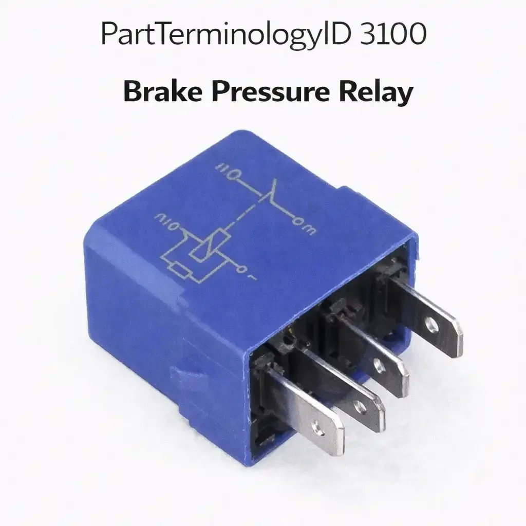
Brake Pressure Relay (PartTerminologyID 3100): Where Circuit Function Identification Prevents Incompatible Relay Specifications Across Four Distinct Brake Circuit Applications
Written by Arthur Simitian | PartsAdvisory
PartTerminologyID 3100, Brake Pressure Relay, is the relay that switches power to a brake pressure sensor circuit, a brake pressure warning system indicator circuit, or a brake hydraulic pressure pump or accumulator circuit based on a brake pressure signal, enabling the brake system module or warning circuit to monitor, maintain, or indicate brake hydraulic pressure status. That definition covers the brake pressure circuit switching function and leaves unresolved the specific function of this relay in the brake circuit architecture, whether it is a pressure sensor power relay, a low-pressure warning indicator relay, a hydraulic accumulator pump enable relay for power-assisted brake systems, or a brake booster vacuum pump relay, all of which may be described as brake pressure relays depending on the vehicle's brake system design.
For sellers, PartTerminologyID 3100 is the brake system relay PartTerminologyID where the circuit function is the mandatory first attribute because four entirely different brake circuit functions share this PartTerminologyID label. A hydraulic accumulator pump relay for a power-assisted brake system on a luxury vehicle operates at substantially higher current than a brake pressure sensor power relay, and the two are completely incompatible despite both being described correctly as brake pressure relays. The listing must identify the specific brake circuit function before any other specification.
What the Brake Pressure Relay Does
In accumulator-type power brake systems, the relay switches the hydraulic pump motor that maintains pressure in the brake accumulator. The accumulator stores hydraulic pressure that provides power-assisted braking without requiring engine vacuum. When accumulator pressure drops below the lower threshold, the relay closes to activate the pump until pressure is restored to the upper threshold. A failed relay in this application leaves the accumulator unable to recharge, progressively reducing brake pedal assist until manual pedal effort is required for braking. The driver experiences an increasingly firm pedal over several brake applications as the accumulator pressure depletes without replenishment.
In brake pressure warning circuits on older vehicles, the relay is a much lower-current component that activates the brake warning indicator lamp when the differential pressure valve between the front and rear brake circuits detects a pressure imbalance from a circuit leak. This relay handles milliamperes of indicator circuit current rather than the tens of amperes of a pump motor circuit. The listing must differentiate these two applications completely because they share nothing except the PartTerminologyID label and the word pressure.
Accumulator pump cycle frequency and relay contact life
The accumulator-type power brake system maintains pressure in the accumulator by cycling the pump on and off throughout the drive cycle as each brake application draws pressure from the stored reserve. On vehicles with frequent stop-and-go driving the pump may cycle dozens of times per hour. Each pump activation event draws motor inrush current through the relay contact, and each deactivation generates a back-EMF arc across the contact gap from the pump motor's stored magnetic energy. The accumulated arc damage over thousands of pump cycles erodes the contact surface progressively, increasing contact resistance and reducing the voltage delivered to the pump motor. Reduced motor voltage decreases pump speed and pressure output, extending the time required to recharge the accumulator after each brake application until the contact resistance increases to the point where the pump cannot maintain adequate accumulator pressure between stops.
High-pressure cutout integration and relay fault symptoms
The brake accumulator system uses a high-pressure cutout switch that stops the pump when the accumulator reaches its upper pressure limit and a low-pressure switch that starts the pump when pressure drops below the lower limit. A failed pump relay prevents the pump from activating on the low-pressure signal, allowing accumulator pressure to continue dropping with each brake application until the accumulator is fully depleted. The driver experiences progressively increasing pedal effort over several brake applications until the accumulator is empty and full manual effort is required for braking. This progressive symptom profile, where the first several stops feel normal and subsequent stops require increasing pedal force, is specific to a failed pump relay in an accumulator brake system and should be described in the listing as the symptom that confirms this relay is the fault source before other brake system components are examined.
Vacuum brake booster relay versus hydraulic accumulator relay confusion
The brake pressure relay label applies to both the vacuum pump enable relay on diesel and hybrid vehicles that use electric vacuum pumps for the brake booster, and to the hydraulic accumulator pump relay on premium vehicles with hydraulic power brakes. These two applications have completely different current requirements. A vacuum pump motor relay for a diesel vehicle typically handles 5 to 10 amperes. A hydraulic accumulator pump relay on a luxury SUV may handle 20 to 30 amperes. Installing the lighter-duty vacuum pump relay in the hydraulic accumulator application results in contact overload on every pump activation cycle. Identifying the specific circuit function in the listing title before any other specification prevents this incompatible substitution at the point of search.
Pressure switch fault diagnosis before relay replacement
The brake pressure low switch triggers the pump relay activation command when pressure drops below the lower threshold. A failed pressure switch that is stuck in the low-pressure position sends a continuous activation command to the relay, running the pump continuously until the high-pressure cutout trips. On a vehicle where the pump runs continuously with no driver brake input and the relay is hot from continuous activation current, the pressure switch is the more likely fault before the relay itself. Testing the pressure switch output signal before condemning the relay prevents unnecessary relay replacement on a relay that is correctly responding to a faulted switch command.
Why This Part Generates Returns
Buyers return brake pressure relays because the accumulator pump relay is delivered for a pressure warning indicator application whose current requirement is a fraction of the pump relay's rating, the brake booster vacuum pump relay is delivered when the buyer needed the hydraulic accumulator relay, the relay is part of the ABS/ESC module assembly and cannot be replaced separately, and the pump motor itself is failed and relay replacement does not restore accumulator pressure because the motor does not run from a confirmed-good relay supply.
Status in New Databases
PIES/PCdb: PartTerminologyID 3100, Brake Pressure Relay
PIES 8.0 / PCdb 2.0: No change.
Listing Requirements
PartTerminologyID: 3100
circuit function: accumulator pump enable, pressure sensor power, warning indicator, or vacuum pump enable (mandatory, in title)
contact current rating appropriate to function (mandatory)
brake system type: hydraulic accumulator, conventional vacuum, or electric vacuum (mandatory)
safety criticality note: brake system component (mandatory)
pump motor fault diagnosis note for accumulator applications (mandatory)
OEM part number cross-reference (mandatory)
FAQ (Buyer Language)
Why is my brake pedal getting harder over several stops?
On accumulator-type power brake systems, a failed accumulator pump relay prevents the pump from recharging the accumulator after each brake application. Pedal effort increases as accumulator pressure depletes. Confirm the pump relay is activating and the pump motor is running before diagnosing accumulator or pump failure.
How do I confirm the pump motor is functional before replacing the relay?
Apply 12 volts directly to the pump motor supply terminal and ground the motor return terminal. The pump motor should activate and run, producing audible pump operation. A motor that does not run from a direct power supply has failed independently of the relay and requires motor replacement before relay replacement will restore accumulator charging function. A motor that runs from direct supply but does not run when the relay is energized confirms the relay contact has failed and is not delivering supply voltage to the motor terminal.
Top Return Scenarios
Scenario 1: "Brake pedal gets harder after several stops, relay replaced, pedal effort returns to normal"
The buyer notices increasing brake pedal effort over a series of stops at low speed. The first stop feels normal and each subsequent stop requires more effort. After confirming the accumulator relay as the fault through voltage testing at the pump motor terminal, the buyer replaces the relay. The pump recharges the accumulator after each brake application and pedal effort returns to normal. This is the correct diagnosis sequence for an accumulator pump relay fault on a power brake system.
Prevention language: "Progressive brake pedal hardening over a series of stops is the characteristic symptom of a failed accumulator pump relay. The first stop depletes a small amount of accumulator pressure and subsequent stops deplete progressively more until manual effort is required. Confirm the pump relay as the fault by measuring voltage at the pump motor supply terminal before ordering."
Scenario 2: "Brake warning lamp on, relay replaced, lamp still on, brake pressure sensor fault code"
The buyer sees a brake system warning lamp and replaces the brake pressure relay. The lamp remains on. A scan tool retrieves a fault code for the brake pressure sensor rather than the pump relay. The sensor is reporting out-of-range pressure data and the BCM is illuminating the warning lamp in response to the sensor fault. The relay replacement had no effect on the sensor fault code.
Prevention language: "Retrieve brake system fault codes before replacing the relay. A brake warning lamp with a pressure-related code may indicate a sensor fault rather than a pump relay fault. Confirm the fault code specifically identifies the relay circuit before ordering a replacement."
Cross-Sell Logic
Brake Accumulator Pump Motor: for buyers where the relay is confirmed functional but the pump motor has seized and requires replacement
Brake Pressure Sensor: for buyers where the fault code identifies a sensor fault rather than a relay fault
Brake Accumulator: for buyers where the pump and relay are confirmed functional but the accumulator has lost its nitrogen charge and cannot hold pressure between brake applications
Catalog Checklist for ACES/PIES Teams
PartTerminologyID = 3100
require circuit function in title: accumulator pump enable, pressure sensor power, warning indicator, or vacuum pump enable (mandatory)
require brake system type: hydraulic accumulator, conventional vacuum, or electric vacuum (mandatory)
require contact current rating appropriate to function (mandatory)
require safety criticality note: brake system component (mandatory)
require pump motor fault diagnosis note for accumulator applications (mandatory)
prevent relay order before pressure switch fault code retrieval: pressure switch fault inhibits relay activation
prevent relay order before pump motor seizure inspection: apply 12 volts directly to the pump motor supply terminal and confirm the motor runs before installing the replacement relay; a motor that does not run from direct supply or draws locked-rotor current has seized and will weld the replacement relay contact within the first activation cycle
Final Take for PartTerminologyID 3100
Brake Pressure Relay (PartTerminologyID 3100) is the brake circuit relay where circuit function identification in the title is the foundational attribute that prevents completely incompatible relay specifications from matching under the same PartTerminologyID label. A hydraulic accumulator pump relay and a brake pressure sensor power relay are both correctly described as brake pressure relays, but they operate at different current levels, in different circuit positions, and serve entirely different functions within the brake system. The accumulator pump relay switches a motor circuit drawing 20 to 40 amperes. The sensor power relay switches a low-current reference supply to a pressure sensor drawing milliamps. Installing the sensor power relay in the pump motor circuit leaves the accumulator unable to recharge, progressively reducing power brake assist until only manual pedal effort remains. Circuit function identification prevents this scenario in its entirety. Brake system type, contact current rating appropriate to the function, and a pump motor fault diagnosis note for accumulator applications complete the four attributes that make every listing under this PartTerminologyID actionable and safe.