HVAC Blower Relay (PartTerminologyID 3084): Where Circuit Role and Blower Resistor Fault Differentiation Prevent the Most Common HVAC Relay Misorder
Written by Arthur Simitian | PartsAdvisory
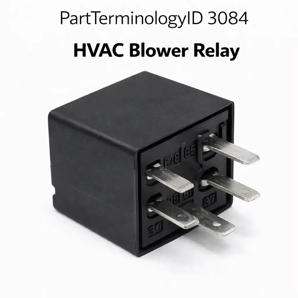
PartTerminologyID 3084, HVAC Blower Relay, is the relay that switches power to the HVAC blower motor circuit, enabling the HVAC control module or manual blower switch to activate air circulation through the vehicle's heating and cooling system by supplying current to the blower motor at one or more speed stages. That definition covers the blower motor power switching function correctly and leaves unresolved whether the relay switches the full motor supply current directly or provides a pilot signal that enables a separate blower motor controller module to manage motor speed, whether the vehicle uses a single blower relay for all speeds or separate relays for each speed stage, the contact current rating relative to the blower motor's startup inrush and maximum-speed current draw, whether the relay is activated by the HVAC control head directly or by a BCM output that processes the control head's signal, and whether a failed relay produces no blower operation at any speed, no blower at a specific speed only, or intermittent blower that cuts in and out during operation.
For sellers, PartTerminologyID 3084 is the HVAC relay PartTerminologyID that most frequently generates catalog confusion with PartTerminologyID 3088, HVAC Blower Motor Relay. The distinction matters: some manufacturers use the term blower relay to describe the main power supply relay for the entire blower circuit, while blower motor relay describes a relay specific to the motor's direct drive circuit on a different architecture. On vehicles where the catalog uses both PartTerminologyIDs, the blower relay enables the circuit and the blower motor relay drives the motor. On vehicles where only one relay is present, it may be cataloged under either ID depending on the data source. Every listing must state the circuit role explicitly to allow buyers to determine which relay their specific fault diagnosis points to.
What the HVAC Blower Relay Does
Single relay versus multi-speed relay architecture
Vehicles with simple manual HVAC controls and a resistor-based blower speed network typically use a single blower relay that switches the full motor supply current at all speeds. The blower speed switch selects which resistor tap supplies the motor, varying the voltage and therefore the speed. The relay switches the supply side of this entire resistor network on and off. When this single relay fails, the blower has no power at any speed setting.
Vehicles with automatic climate control and electronic blower speed management may use separate relays for different speed ranges or separate relays for the blower supply and the blower controller module power supply. A failed supply relay leaves the blower completely inoperative. A failed controller power relay leaves the controller unable to command the motor while the motor supply remains energized, producing a blower that runs at one default speed regardless of the control head setting. Identifying which relay role has failed requires testing both the supply relay and the controller relay before condemning either component.
Contact current rating and blower motor inrush
Blower motors draw their highest current at startup and at maximum speed. A typical HVAC blower motor draws 15 to 25 amperes at maximum speed on a full-size vehicle. At startup the inrush may briefly reach 30 to 40 amperes. A relay with a 20-amp contact rating is marginal for a motor that regularly draws 25 amperes at max speed, and the contact will erode over time from the repeated inrush events at each blower activation. The accumulated contact resistance increase produces a voltage drop at the motor that reduces maximum-speed airflow noticeably before the relay fails completely.
This sub-failure degradation is particularly problematic for HVAC blower relays because reduced maximum-speed airflow on a hot day is a serious comfort complaint that the driver may attribute to the blower motor, the evaporator, or the refrigerant charge before the relay contact resistance is measured. A relay contact resistance test with a milliohm meter at the relay socket before condemning other HVAC components is a 30-second diagnostic step that can prevent unnecessary HVAC component replacement. The listing must include contact resistance measurement as a diagnostic recommendation alongside the visual symptom description.
HVAC control module output and BCM integration
On modern automatic climate control systems the blower relay is typically commanded by the HVAC control module or BCM based on the target temperature, the current cabin temperature from the in-car sensor, and the blower speed setting selected on the control head. The relay coil must be within the module's driver output tolerance. A replacement relay with a coil resistance below the minimum tolerance draws more current than the module driver was designed to supply, overheating the driver output transistor and potentially damaging the HVAC module. On BCM-controlled blower relay architectures, confirming the coil resistance before installation is as important as confirming the contact current rating.
Why This Part Generates Returns
Buyers return HVAC blower relays because the relay is the supply relay and the module power relay is also failed, leaving the blower non-functional after the supply relay is replaced, the contact current rating is below the motor's maximum-speed current draw producing reduced airflow at high speed rather than complete no-blower failure, the replacement relay coil resistance is below the HVAC module driver tolerance and the module output transistor overheats after installation, the blower resistor block is the actual faulted component and the relay replacement does not restore the inoperative speed because the resistor has an open circuit at that tap, and the relay is integrated into the HVAC control module assembly and cannot be replaced as a separate external component on this vehicle.
Status in New Databases
PIES/PCdb: PartTerminologyID 3084, HVAC Blower Relay
PIES 8.0 / PCdb 2.0: No change.
Top Return Scenarios
Scenario 1: "Blower resistor faulted, specific speed missing, relay is not the cause"
The buyer's blower works at some speeds but not at low speed. The listing for a blower relay appears in the search results. The buyer orders the relay. Installation does not restore low speed. The blower resistor has an open circuit at the low-speed tap. The relay switches the entire circuit and has no role in individual speed selection. Low speed is absent because the resistor is failed, not the relay.
Prevention language: "Diagnostic note: A blower that operates at some speeds but not others indicates a blower resistor fault, not a relay fault. The blower relay switches the entire circuit. A speed-selective failure points to the resistor network. Verify all speeds are absent before ordering a relay replacement."
Scenario 2: "Contact current below motor max speed, reduced airflow at high setting"
The replacement relay has a 20-amp contact rating. The motor draws 24 amperes at max speed. The relay operates but the contact resistance produces a 1.5-volt drop at the motor supply terminal. Airflow at maximum speed is noticeably reduced from the original. The blower seems underpowered but not completely inoperative.
Prevention language: "Contact rating: [X amps continuous]. Verify the motor's maximum speed current draw does not exceed the contact rating. A relay with insufficient contact rating produces reduced airflow at high speed rather than complete blower failure. Use the motor's nameplate or wiring diagram to confirm maximum current draw before ordering."
Listing Requirements
PartTerminologyID: 3084
circuit role: main supply relay, controller module power relay, or speed-stage relay (mandatory)
contact current rating: continuous and inrush (mandatory)
activation source: HVAC control head, HVAC module, or BCM (mandatory)
coil resistance within module driver tolerance (mandatory for module-controlled)
standalone versus module-integrated relay (mandatory)
blower resistor fault diagnostic note (mandatory)
differentiation from HVAC Blower Motor Relay (PartTerminologyID 3088): state circuit role distinction explicitly (mandatory)
OEM part number cross-reference (mandatory)
Catalog Checklist for ACES/PIES Teams
PartTerminologyID = 3084
require circuit role in title (mandatory)
require contact current rating with inrush note (mandatory)
require coil resistance for module-controlled applications (mandatory)
require blower resistor diagnostic note (mandatory)
prevent catalog conflation with PartTerminologyID 3088: both IDs may appear on the same vehicle; the circuit role distinguishes them and must be stated in the listing
prevent contact current undersizing: reduced blower airflow from sub-rated contact resistance is a degradation-mode failure that generates complaints before complete failure occurs
FAQ (Buyer Language)
Why does my blower work at some speeds but not others?
Individual speed loss points to the blower resistor block, not the relay. The relay switches the entire circuit. Replace the blower resistor for a speed-selective fault. Order a relay only when all speeds are absent simultaneously.
Why is my blower weaker than before after relay replacement?
The replacement relay contact rating is below the motor's maximum-speed current draw. The contact resistance causes a voltage drop at the motor supply terminal that reduces motor speed. Replace with a relay rated for the motor's full maximum-speed current.
What is the difference between the blower relay and the blower motor relay?
On vehicles with both, the blower relay enables the entire blower circuit and the blower motor relay drives the motor directly. A fault in either produces no-blower symptoms but at different circuit points. Identify which circuit the fault code or voltage test points to before ordering.
How do I confirm the blower relay is the fault before ordering?
Verify the relay coil is receiving activation voltage at the relay socket's coil terminals when the blower is switched on. If coil voltage is present but the blower does not run, substitute a known-good relay of the correct specification. If the blower restores with the substituted relay, the original relay's contact has failed. If no coil voltage is present at the socket, the fault is in the HVAC control head or module output.
Can the HVAC control head cause the blower relay to fail prematurely?
Yes. A control head output that delivers undersized coil voltage or intermittent coil signal can cause relay contact chatter and accelerated contact erosion. If the replacement relay fails again within a short service interval, test the coil supply voltage from the control head output against the relay's minimum operating voltage specification.
Scenario 3: "Module-controlled application, HVAC module output fault, coil voltage absent"
The blower is inoperative. The relay coil terminal shows no voltage at the relay socket when the blower is commanded on. The buyer replaces the relay. The relay coil still shows no voltage. The HVAC control module's relay driver output pin has failed open. Confirming coil activation voltage before ordering would have identified this scenario before the replacement relay was purchased.
Prevention language: "HVAC module output check: Before ordering, verify the relay coil terminal shows activation voltage when the blower is commanded on. Absent coil voltage indicates a module or control head output driver fault rather than a relay fault."
Scenario 4: "Contact current rating marginal, blower cuts out intermittently at max speed in summer"
The replacement relay contact rating is marginally sufficient for startup current but not for sustained maximum-speed current under elevated under-hood temperatures. In summer conditions the relay socket temperature adds to the contact temperature rise. The contact operates normally on cold mornings but fails intermittently during hot-weather maximum-speed operation.
Prevention language: "Contact thermal derating: In high-ambient-temperature climates, specify a relay with a contact rating of at least 25 percent above the motor's measured maximum-speed current to maintain thermal margin under sustained high-speed summer operation."
Application Range and Fitment Guidance for PartTerminologyID 3084
HVAC blower relay applications span all vehicles equipped with electric blower motors from approximately the early 1970s forward. The relay architecture evolved from simple manual switch-driven relays through HVAC module-controlled high-current switching in modern dual-zone and multi-zone climate control systems. Contact current ratings for blower relay applications have increased with the transition to larger-motor multi-speed HVAC systems in trucks and SUVs. A compact car blower motor may draw 12 to 15 amperes at maximum speed. A full-size truck with a high-capacity HVAC system may draw 20 to 30 amperes at maximum speed. A single contact current rating published across a mixed-load fitment range may understate the requirement for the high-load vehicles in the range.
The coexistence of PartTerminologyID 3084 and PartTerminologyID 3088 on the same vehicle platform is a significant catalog quality challenge. Both IDs must be published with distinct circuit role descriptions to prevent buyers from ordering under the wrong ID. A buyer who receives a PartTerminologyID 3084 relay for a vehicle whose fault code points to the PartTerminologyID 3088 circuit installs the relay in the wrong position and finds no change in the blower symptom. The circuit role in the listing title is the only attribute that allows a buyer to match the relay to the specific faulted circuit position without wiring diagram access.
What Sellers Get Wrong About PartTerminologyID 3084
The most common error is listing the blower relay without a blower resistor diagnostic note. The blower resistor fault generates returns for the blower relay at a higher rate than any other misdiagnosis scenario for this PartTerminologyID. A buyer with a speed-selective blower fault who searches for a blower relay will find listings under this PartTerminologyID because blower relay is the most natural search term for any blower circuit fault. The listing that does not redirect speed-selective fault buyers toward the blower resistor will receive and process a return on every order from a speed-selective fault buyer. The redirect takes one sentence and converts every such return into either a blower resistor order or a confirmed all-speeds-absent blower relay diagnosis.
The second most common error is not distinguishing PartTerminologyID 3084 from PartTerminologyID 3088 in the listing. On vehicles with both relays, a buyer who orders under 3084 expecting to resolve the fault pointed to by the 3088 circuit receives a relay for the wrong circuit position. Both relays serve the blower system. Without explicit circuit role identification, a buyer has no way to know which position the listing covers without the vehicle's wiring diagram. Every listing under PartTerminologyID 3084 on a vehicle that also has PartTerminologyID 3088 must state the circuit role difference or risk the return rate from buyers who installed the relay in the wrong position.
Cross-Sell Logic
HVAC Blower Motor Resistor: the most common cause of speed-selective blower fault that buyers misdiagnose as a relay fault; cross-sell with every blower relay listing that does not explicitly exclude speed-selective faults
HVAC Blower Motor Relay (PartTerminologyID 3088): the companion relay on vehicles with separate supply and motor drive relays; both may need replacement if both circuits are faulted
HVAC Blower Motor: for buyers whose relay diagnosis confirms the relay is activating but the motor does not run; a motor that does not respond to a confirmed-good relay supply has failed internally
Final Take for PartTerminologyID 3084
HVAC Blower Relay (PartTerminologyID 3084) is the HVAC circuit relay where circuit role identification, differentiation from PartTerminologyID 3088, blower resistor diagnostic note, and contact current rating for full motor load are the four attributes that prevent the four most common return and misdiagnosis scenarios. The blower resistor diagnostic note alone prevents the single most common misorder in the HVAC relay segment: a relay ordered for a speed-selective fault that is actually a resistor fault. The circuit role distinction prevents the wrong-position relay order on dual-relay HVAC systems. Contact current rating at full motor load prevents the degradation-mode failure that manifests as reduced airflow rather than complete blower loss. And HVAC module output driver confirmation before ordering prevents the return from buyers who replace the relay without confirming the module is commanding activation. All four attributes require one sentence each in the listing, and all four are absent in most commodity aftermarket listings for this PartTerminologyID.