Back Up Light Relay (PartTerminologyID 3072): Where Camera Integration Disclosure and Relay Existence Verification Prevent Dual-System Misdiagnosis
Written by Arthur Simitian | PartsAdvisory
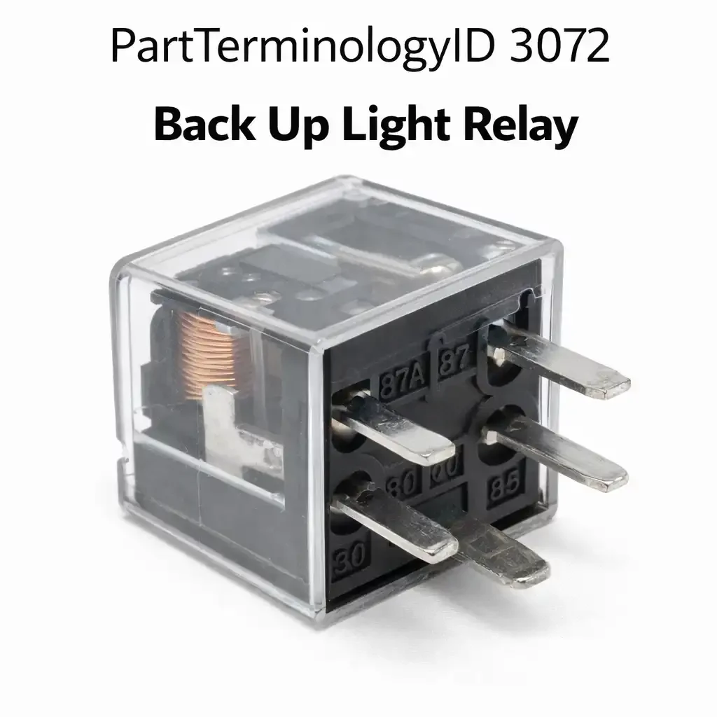
PartTerminologyID 3072, Back Up Light Relay, is the relay that switches power to the vehicle's rear-facing white lamps that activate when the transmission is placed in the reverse gear position, providing illumination behind the vehicle to assist the driver in reversing maneuvers and warning pedestrians and other vehicles of the vehicle's backward movement. That definition covers the reverse lamp circuit switching function correctly and leaves unresolved whether the relay is activated by a direct reverse gear position switch signal in the transmission or a BCM output that receives the reverse signal from the transmission range sensor on the CAN bus, the contact current rating for the total combined wattage of the rear lamps and any trailer connector lighting circuits switched through the same relay, whether the relay activates both the backup lamps and a backup camera power supply through the same contact or through separate outputs, and whether a separate relay exists or whether the reverse lamp circuit is switched directly from the reverse gear position switch without a relay on simpler wiring architectures.
For sellers, PartTerminologyID 3072 is the lighting relay PartTerminologyID where the reverse camera power supply integration is the fastest-growing return scenario in the catalog, because vehicles built from approximately 2010 onward increasingly route the backup camera power supply activation through the same reverse lamp relay or a relay in parallel with it, and a failed backup lamp relay on these vehicles disables both the reverse lamps and the backup camera simultaneously. A buyer who reports a backup camera that stopped working along with the reverse lights has a relay fault that affects both systems rather than two separate component failures. The listing must note the dual-system disability from a single relay failure as a diagnostic pointer that saves buyers from investigating the camera module before the relay is confirmed.
What the Back Up Light Relay Does
Transmission range sensor versus reverse switch activation
The backup light relay receives its coil activation signal from one of two sources depending on the vehicle's electrical architecture. Older vehicles and some current applications with manual transmissions use a mechanical switch mounted on the transmission housing that closes a direct 12-volt circuit to the relay coil when the shift lever engages the reverse gear detent. This switch is a simple on-off contact that requires no module processing and provides a low-latency activation signal that illuminates the backup lamps within milliseconds of shift engagement.
Vehicles with electronic shift selectors and automatic transmissions on CAN bus architectures use a transmission range sensor that reports gear position to the TCM or PCM over the CAN bus. The BCM receives the reverse gear position message from the CAN bus and activates the backup lamp relay through a BCM output. The activation latency in this architecture is 50 to 200 milliseconds longer than the direct switch architecture because the CAN bus message must complete its full communication cycle before the BCM commands the relay. A replacement relay for a BCM-controlled architecture must match the BCM output's coil resistance tolerance, while a replacement for a direct-switch architecture requires only correct coil voltage and contact rating.
Trailer wiring and the increased contact current requirement
On trucks and SUVs with factory trailer towing packages, the backup lamp relay circuit may include the trailer connector's reverse lamp output, which activates the trailer's reverse lamps simultaneously with the vehicle's own backup lamps. The combined current of the vehicle's two backup lamps plus a trailer's two backup lamps may reach 10 to 15 amperes for incandescent lamp configurations. A relay sized for the vehicle's own backup lamps alone, typically 3 to 6 amperes, is undersized for the trailer-inclusive current. The listing must note the trailer wiring current addition for towing package vehicles and must specify a relay with adequate contact rating for the trailer-inclusive load.
Backup camera integration and the dual-system fault symptom
On vehicles where the backup camera receives its power supply activation from the backup lamp relay, the camera module activates simultaneously with the backup lamps when the relay closes. This integration means a failed relay simultaneously disables the backup lamps and the backup camera, producing the distinctive dual-system fault symptom. On vehicles where the camera has a dedicated relay separate from the backup lamp relay, only the backup lamps are affected by a backup lamp relay failure. The listing must identify whether the specific vehicle integrates camera power through the backup lamp relay or uses a separate camera power relay, because the dual-system fault symptom is a strong diagnostic pointer to the relay rather than the camera module only on integrated architectures.
Why This Part Generates Returns
Buyers return backup light relays because a separate backup lamp relay does not exist on this vehicle and the reverse lamps are switched directly from the transmission reverse switch without a relay, the BCM-controlled relay coil resistance is outside tolerance and the BCM output fault prevents relay activation after a new relay is installed, the trailer wiring contact current exceeds the relay rating and the contact fails under combined vehicle and trailer load, and the backup camera is a separate system with its own power relay and the backup lamp relay replacement does not restore camera operation as the buyer expected after reading a listing that did not distinguish integrated from separate camera power architectures.
Why Catalog Data Quality Matters for PartTerminologyID 3072
The backup lamp relay listing that generates the fewest returns is the one that answers the buyer's four pre-order questions before the buyer has to ask them: does a separate relay exist on my vehicle, does my camera share this relay circuit, is the contact rating sufficient for my trailer, and is my BCM actually commanding the relay. A listing that answers all four questions converts a potential return into a successful installation and a confident buyer. Each of these four questions requires at most one sentence to answer in the listing. The aggregate investment is four sentences. The return rate reduction from those four sentences is the most efficient return prevention available under this PartTerminologyID.
Status in New Databases
PIES/PCdb: PartTerminologyID 3072, Back Up Light Relay
PIES 8.0 / PCdb 2.0: No change.
Top Return Scenarios
Scenario 1: "No separate relay, reverse lamp switched directly from transmission switch"
The buyer orders a backup light relay. On this vehicle the reverse lamps are wired directly from the transmission reverse switch without a relay. No relay socket exists in the fuse center for this circuit. The delivered relay cannot be installed.
Prevention language: "Relay architecture: Verify the vehicle uses a relay-switched backup lamp circuit before ordering. On some vehicles the reverse lamp circuit is switched directly from the transmission reverse switch without a relay. Confirm the relay socket exists in the fuse center before purchase."
Scenario 2: "Backup camera still not working after relay replacement, separate camera relay"
The buyer replaces the backup lamp relay expecting both backup lamps and camera to restore. The backup lamps restore. The camera remains inoperative because it has a separate power relay independent of the backup lamp circuit. The listing did not distinguish the two architectures.
Prevention language: "Backup camera integration: [Camera power integrated through backup lamp relay on this application / Camera uses separate power relay on this application]. A backup camera that remains inoperative after backup lamp relay replacement has a separate camera power circuit fault that requires separate diagnosis."
Scenario 3: "Trailer current exceeds relay contact rating, contact fails under towing load"
The buyer replaces the relay. The backup lamps work correctly without the trailer attached. On the first towing use with a trailer, the backup lamps flicker briefly and then go dark. The trailer's two backup lamps add 4 to 5 amperes to the vehicle's existing backup lamp load. The replacement relay's contact was rated for the vehicle's original backup lamp load of 6 to 8 amperes. The combined load of 10 to 13 amperes exceeds the contact rating at the relay's thermal limit after a few minutes of operation, causing the contact to open from thermal overload.
Prevention language: "Trailer towing note: If the vehicle is equipped with a trailer wiring harness, the backup lamp relay must be rated for the combined current load of vehicle backup lamps plus trailer backup lamps. Add the trailer's backup lamp wattage to the vehicle's backup lamp wattage, divide by 12 volts to determine total current, and verify the relay contact rating exceeds this combined load."
Scenario 4: "BCM coil driver fault, relay correctly not activating, fault attributed to relay"
The reverse lamps are inoperative. The relay is replaced. The lamps remain inoperative. The BCM's output driver pin for the backup lamp relay circuit has failed open due to an internal driver transistor failure. The BCM is not commanding the relay coil to energize regardless of gear selector position. The relay coil receives no activation voltage, and the relay contact remains open. A new relay is equally unresponsive because the activation signal is absent. Confirming the presence of coil activation voltage at the relay socket terminals before ordering a relay would have identified this scenario before the order was placed.
Prevention language: "Relay activation diagnosis: Before ordering, verify the relay coil terminals in the relay socket show activation voltage when the transmission is shifted to reverse. Absent activation voltage with the relay removed indicates a BCM output fault, not a relay fault. Replacing the relay without confirming coil activation voltage present at the socket will not restore backup lamp operation."
PartTerminologyID: 3072
relay existence verification: confirm relay-switched architecture (mandatory)
activation source: direct transmission switch or BCM CAN bus output (mandatory)
contact current rating including trailer wiring where applicable (mandatory)
backup camera integration: integrated or separate relay (mandatory)
coil resistance for BCM-controlled applications (mandatory)
OEM part number cross-reference (mandatory)
Listing Requirements
PartTerminologyID: 3072
relay existence verification: confirm separate relay exists on vehicle (mandatory)
contact current rating: vehicle lamps plus trailer load where applicable (mandatory)
backup camera integration: shared or separate circuit (mandatory)
activation source: BCM output or transmission range sensor (mandatory)
coil resistance within BCM driver tolerance (mandatory for BCM-controlled)
trailer wiring current addition note (mandatory)
OEM part number cross-reference (mandatory)
Catalog Checklist for ACES/PIES Teams
PartTerminologyID = 3072
require relay existence verification note (mandatory)
require backup camera circuit integration disclosure (mandatory)
require contact current rating including trailer lamp load (mandatory)
require BCM coil driver tolerance specification (mandatory for BCM-controlled)
prevent relay order on direct-switched vehicles: no relay socket exists; buyer receives component with no installation point; relay existence must be confirmed before listing is published
prevent camera misdiagnosis: backup camera inoperative with backup lamps working indicates separate camera circuit fault, not relay fault; integration disclosure prevents unnecessary relay order when camera fault is actual issue
prevent trailer towing contact overload: combined vehicle-plus-trailer lamp load must be used as contact current requirement when trailer wiring is installed; single-vehicle lamp load as the only contact rating is incomplete for towing applications
FAQ (Buyer Language)
Why did my backup camera also stop working when the reverse lights failed?
On vehicles with integrated backup camera power through the backup lamp relay, both systems lose power simultaneously when the relay fails. Replacing the relay restores both. If the camera remains inoperative after relay replacement, the camera has a separate power circuit fault.
Do I need a higher-rated relay if I tow a trailer?
Yes. The trailer's reverse lamps add 2 to 5 amperes to the backup lamp relay's contact load. A relay sized only for the vehicle's own backup lamps may be undersized for the combined vehicle-plus-trailer load. Use the combined lamp wattage to determine the required contact rating.
My reverse lights work but my backup camera does not. Is the relay the problem?
If the reverse lamps are working, the backup lamp relay is functioning correctly and is not the cause of the camera failure. The camera is either powered by a separate relay with its own fault, has a failed camera module, or has a damaged video signal cable. Replacing the backup lamp relay will not restore camera function when the lamps are already operational.
Does my vehicle have a backup light relay or does it switch directly from the transmission?
Both architectures exist. Check the fuse center diagram for a relay position labeled reverse lamp, backup lamp, or back-up light. If no such relay position appears, the reverse lamps are switched directly from the transmission range sensor or reverse switch without a relay. On direct-switched vehicles, a dead backup lamp circuit with a confirmed good bulb and fuse indicates a failed transmission range sensor or reverse switch, not a relay fault.
Cross-Sell Logic
Backup Camera: for buyers where the relay is confirmed functional and the backup lamps have restored but the camera remains inoperative, indicating a camera module or video signal fault independent of the relay circuit
Transmission Range Sensor: for vehicles where no backup lamp relay exists and the reverse lamps fail to activate because the direct-switched range sensor output has failed
Trailer Wiring Harness: for buyers with trailer towing applications where the combined vehicle-plus-trailer backup lamp current exceeds the original relay contact rating, requiring a higher-rated relay alongside the updated trailer wiring
Backup Lamp Bulb and Socket: for buyers whose backup lamp circuit fuse and relay are confirmed functional but no lamp illumination occurs, indicating a failed bulb, corroded socket, or open lamp ground circuit
What Sellers Get Wrong About PartTerminologyID 3072
The most common error under PartTerminologyID 3072 is publishing the listing without verifying that a separate backup lamp relay exists on the vehicle. On a significant number of vehicles, particularly earlier model years and base-trim vehicles without backup camera integration, the reverse lamps are switched directly from the transmission range sensor output without any relay in the circuit. A buyer on one of these vehicles who orders a backup lamp relay receives a component with no socket to install it into. The existence verification is a mandatory pre-publication step that prevents every return from this segment of buyers.
The second most common error is not disclosing whether the backup camera circuit is integrated through the backup lamp relay or powered by a separate relay circuit. Modern vehicles almost universally integrate backup cameras, and buyers assume the camera and the backup lamps share a common circuit. On vehicles where they share the relay, this assumption is correct and the listing must state it so buyers know a single relay replacement restores both. On vehicles where they are separate, a buyer who expects the camera to restore with the backup lamps will find it still inoperative after relay replacement and will attribute the continuing camera fault to the relay, returning it as defective. The camera's separate circuit must be disclosed to prevent this specific return scenario.
The third error is using a single contact current rating that accounts only for the vehicle's installed backup lamps without noting the trailer lamp addition for vehicles with trailer wiring capability. This error is particularly consequential because it only manifests during towing, which may be weeks or months after the initial installation when the buyer first uses the vehicle with a trailer. The contact failure under combined vehicle-plus-trailer load appears to be a failed relay when it is actually a relay correctly rated for vehicle-only use that is being asked to carry a combined load it was not specified to handle.
Final Take for PartTerminologyID 3072
Back Up Light Relay (PartTerminologyID 3072) is the reverse lighting relay where relay existence verification, backup camera integration disclosure, and trailer wiring current rating are the three attributes that prevent the three most distinct return scenarios and give buyers the diagnostic context to identify the relay as the single cause of what may appear to be a dual-system failure. On vehicles where the backup lamp relay also powers the camera, a single relay failure produces what appears to be two simultaneous system failures. Without the integration disclosure, the buyer assumes the camera and lamps have separate faults and begins a multi-component diagnostic process that leads to multiple orders before the single relay failure is identified. The relay existence verification prevents the order from proceeding on vehicles where no relay socket exists. The trailer current rating prevents a contact failure on the first towing use after relay replacement. All three disclosures are preventable with one sentence each in the listing, and all three produce returns and multi-component misdiagnosis chains when they are absent.
The BCM coil activation voltage diagnostic note rounds out the four pre-order steps that a buyer should complete before placing an order under this PartTerminologyID: verify a relay socket exists, verify coil activation voltage is present at the socket in reverse gear, verify the camera integration architecture, and verify the contact current rating covers trailer lamp addition where applicable. A buyer who completes all four steps before ordering has confirmed the relay is the fault source, confirmed the replacement relay specification matches the circuit, and confirmed the installation will restore both backup lamp and camera function where the camera is integrated. A buyer who completes none of these steps orders on assumption and may return the relay for any of four distinct reasons, none of which would have occurred with pre-order verification.
Relay existence verification is the lowest-effort return prevention step available under any relay PartTerminologyID. It requires confirming one fact: whether a relay socket for this circuit exists in the fuse center diagram for the specific vehicle. That confirmation takes less time than processing a single return. Every listing that omits it will generate at least one return per direct-switched vehicle that appears in the fitment range.