Auxiliary Battery Relay (PartTerminologyID 3056): Where Latching Architecture and Charging Current Rating Determine Whether the Dual-Battery System Isolates Correctly
Written by Arthur Simitian | PartsAdvisory
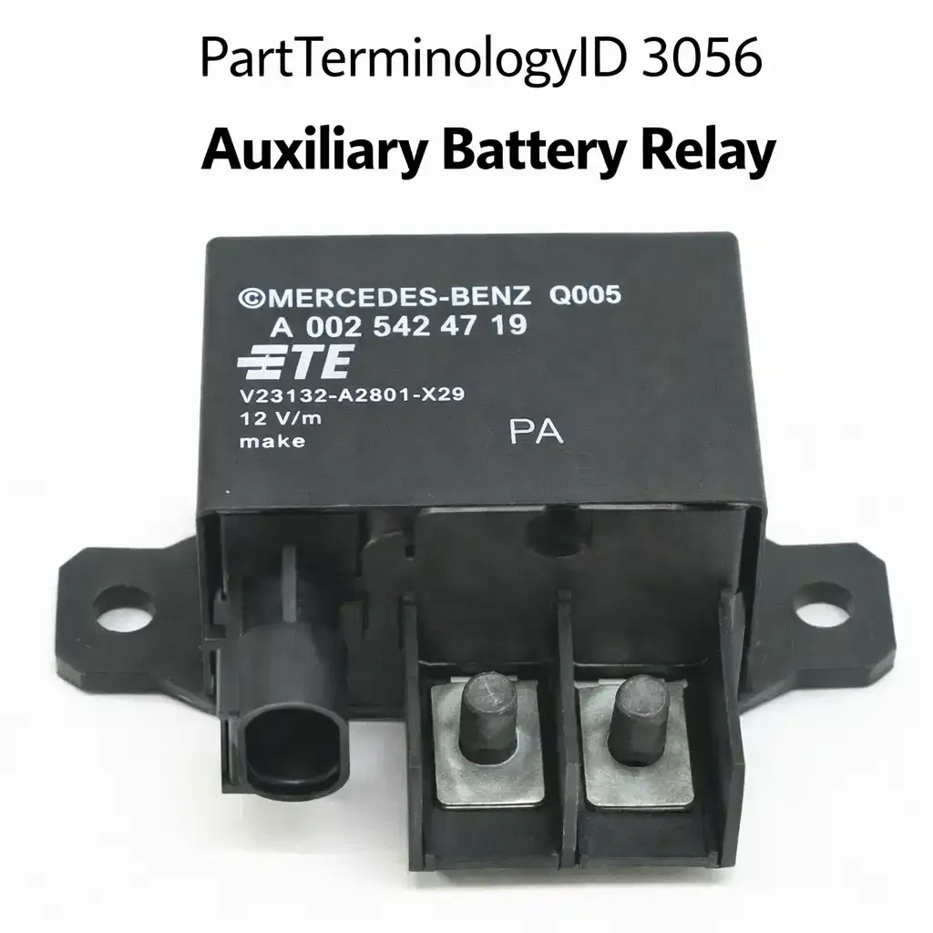
PartTerminologyID 3056, Auxiliary Battery Relay, is the relay that connects or isolates the vehicle's auxiliary battery from the main starting battery, enabling the battery management system or dual-battery controller to charge the auxiliary battery from the alternator when the engine is running while isolating it from the main battery when the engine is off to prevent accessory loads from discharging the main battery below the minimum starting voltage. That definition covers the dual-battery isolation function correctly and leaves unresolved whether the relay is a simple voltage-sensing isolator relay that closes on charge voltage detection or a bidirectional DC-DC isolator that actively manages charging current in both directions, the contact current rating for the combined charging and discharge current that flows through the relay during alternator charging, the relay's quiescent current draw when de-energized in the isolated state, and whether the relay is a latching relay that holds its last commanded state without continuous coil energization or a non-latching relay that requires continuous coil current to maintain the connected state.
For sellers, PartTerminologyID 3056 is the dual-battery relay PartTerminologyID where latching versus non-latching relay architecture is the most buyer-confusing distinction. A non-latching auxiliary battery relay requires continuous coil energization to hold the batteries connected during alternator charging. If the relay coil current draw is added to the vehicle's accessory load when calculating alternator capacity, a non-latching relay that draws 150 to 200 milliamperes continuously while connected represents a small but continuous parasitic load. A latching relay commands a brief current pulse to switch states and then holds the state without any coil current, drawing zero parasitic current in either state. On vehicles where the auxiliary battery relay is expected to remain connected for extended charging periods, the latching architecture significantly reduces parasitic coil current compared to a continuously-energized non-latching relay.
What the Auxiliary Battery Relay Does
When the vehicle's alternator output raises the electrical system voltage above the threshold set by the battery management system, typically 13.2 to 13.8 volts depending on the manufacturer, the controller closes the auxiliary battery relay to connect the auxiliary battery to the charging circuit. Alternator current flows through the relay contact to charge the auxiliary battery alongside the main battery. When the engine stops and the system voltage drops below the threshold, the controller opens the relay to isolate the auxiliary battery, preventing the auxiliary battery's loads such as refrigerators, lighting, or winches from discharging back through the main battery circuit and depleting the main battery below the cranking threshold.
The contact current rating must account for the full charging current that flows through the relay from the alternator to the auxiliary battery. On vehicles with large auxiliary batteries and high-output alternators, this charging current may reach 50 to 100 amperes during bulk charging phase. A relay rated for 30 amperes in this application will overheat the contact and produce accelerated contact erosion and resistance growth within the first charge cycle after a deep auxiliary battery discharge.
Charging current path and the alternator output requirement
When the auxiliary battery relay closes, the alternator must supply charging current to both the main battery and the auxiliary battery simultaneously. On vehicles with small alternators and large auxiliary batteries, closing the relay during a high-demand condition can cause the alternator's output voltage to sag if the combined battery charging current exceeds the alternator's continuous output rating. The battery management system on premium vehicles manages this by commanding relay closure only when the alternator has sufficient headroom above the accessory load to supply auxiliary battery charging current without voltage sag. A replacement relay that closes at a lower voltage threshold than the original may close when the alternator is already at capacity, causing charging system voltage sag that triggers other fault codes unrelated to the relay itself.
Isolation in parked state and the discharge prevention function
The auxiliary battery relay's open state while the vehicle is parked prevents the auxiliary battery from back-feeding current to the main battery through the relay contact if the main battery develops a lower voltage than the auxiliary battery from a parasitic drain. Without relay isolation, a deeply discharged main battery would draw current from the auxiliary battery through the closed relay contact until both batteries are equally discharged, leaving the vehicle unable to start. The relay's isolation function is as important as its charging connection function, and a relay that fails closed in the parked state eliminates the isolation protection that prevents dual battery discharge from a single main battery drain event.
Latching relay architecture and the reset requirement
Latching relays used in dual-battery applications hold their last commanded state without continuous coil current. Once commanded to the closed position by a single pulse from the battery management system, the latching relay remains closed even if the BMS control signal is removed, drawing no coil current in the held state. A latching relay replacement installed in a non-latching relay socket, or vice versa, produces unexpected behavior: a latching relay in a non-latching circuit remains in its last state indefinitely when the BMS removes the command signal, never opening to isolate the auxiliary battery. A non-latching relay in a latching circuit requires continuous coil current to remain closed, drawing continuous power from the BMS output driver and potentially exceeding the driver's current capacity if the driver was designed only for the brief pulse required by a latching relay.
High-current auxiliary loads and the relay contact stress profile
Auxiliary batteries in commercial vehicles, ambulances, and service vehicles frequently supply high-current loads including refrigeration units, lift gate motors, and emergency lighting systems that draw significantly more current than typical passenger vehicle auxiliary accessories. The auxiliary battery relay in these applications must be rated for the combined peak current of all auxiliary loads, not just the charging current. A relay rated for alternator charging current of 80 amperes may be insufficient for a refrigeration unit drawing 60 amperes combined with a lift gate motor drawing 40 amperes simultaneously during an unloading operation.
Why This Part Generates Returns
Buyers return auxiliary battery relays because the contact current rating is sized for a light-duty auxiliary load application and the actual charging current from a high-output alternator to a large auxiliary battery exceeds the contact rating, a non-latching relay is delivered for an application that requires a latching relay and the replacement draws continuous coil current that the battery management controller was not designed to supply continuously, and the voltage sensing threshold of the replacement relay differs from the original causing the relay to connect before the alternator has fully stabilized its output voltage or to disconnect prematurely during low engine speed charging.
Status in New Databases
PIES/PCdb: PartTerminologyID 3056, Auxiliary Battery Relay
PIES 8.0 / PCdb 2.0: No change.
Listing Requirements
PartTerminologyID: 3056
relay architecture: latching or non-latching (mandatory)
contact current rating: continuous charging current (mandatory)
voltage sensing threshold where applicable (mandatory)
quiescent current draw in isolated state (mandatory for non-latching)
OEM part number cross-reference (mandatory)
FAQ (Buyer Language)
What is the difference between a latching and non-latching auxiliary battery relay?
A latching relay holds its state after a brief command pulse and draws no coil current while holding. A non-latching relay requires continuous coil current to maintain the connected state. For extended charging periods, a latching relay eliminates continuous parasitic coil current draw.
Why is my main battery draining even with an auxiliary battery relay installed?
The relay voltage sensing threshold may be set too low, connecting the batteries below the alternator's stable charge voltage so the auxiliary battery draws current from the main battery rather than from the alternator. Verify the relay's connection threshold is above the fully charged battery resting voltage of approximately 12.7 volts.
How do I confirm the relay is operating in the correct charging state?
With the engine running and the charging system producing above-threshold voltage, measure voltage at both the main battery terminal and the auxiliary battery positive terminal. If both read similar voltage above 13.5 volts, the relay is closed and both batteries are receiving charge current. If the auxiliary battery reads below 13 volts while the main battery is above 13.5 volts, the relay is open and not connecting the auxiliary battery to the charging circuit. Confirm the relay coil terminal is receiving its activation signal from the battery management system before ordering a replacement relay.
Top Return Scenarios
Scenario 1: "Main battery draining overnight despite auxiliary relay installed"
The buyer installs an auxiliary battery relay to isolate the auxiliary battery from the main battery when the engine is off. The main battery continues to drain overnight. Testing confirms the relay contact is failing closed in the parked state, allowing current to flow between the batteries. A high-draw auxiliary accessory is discharging both batteries through the failed-closed relay contact. The relay requires replacement and the auxiliary accessory parasitic draw must be identified and resolved.
Prevention language: "An auxiliary battery relay that fails closed in the parked state allows current to flow between the main and auxiliary batteries. If the main battery drains overnight after relay installation, test the relay contact resistance in the de-energized state. A contact that shows less than several ohms resistance when the coil is de-energized has failed closed and requires replacement."
Scenario 2: "Auxiliary battery not charging after relay installation"
The buyer installs the relay but the auxiliary battery does not charge during engine operation. Testing confirms the relay coil receives no activation voltage from the battery management system because the BMS has detected a voltage sag event and inhibited relay closure to protect the alternator. The auxiliary battery has an internal cell fault that draws excessive charge current when connected, causing the voltage sag that triggers the BMS inhibit. The relay is operating correctly by remaining open in response to the BMS inhibit signal.
Prevention language: "Confirm the auxiliary battery is serviceable before installing the relay. An auxiliary battery with an internal fault that draws excessive charge current will cause the battery management system to inhibit relay closure to protect the charging system. The relay will not close to connect the auxiliary battery until the BMS fault condition is resolved."
Cross-Sell Logic
Battery Management System Module: for buyers where the relay coil receives no activation signal because the BMS has inhibited charging relay closure
Auxiliary Battery: for buyers where the auxiliary battery has an internal fault causing excessive charge current draw that triggers BMS inhibit
Battery Isolator: for buyers who require charge isolation without a relay-based architecture on simpler dual-battery installations
Catalog Checklist for ACES/PIES Teams
PartTerminologyID = 3056
require contact architecture: latching or non-latching (mandatory)
require contact current rating for peak auxiliary load and charging current (mandatory)
require activation source: BMS output, voltage threshold, or manual switch (mandatory)
require voltage threshold specification for threshold-activated relays (mandatory)
require high-current auxiliary load note for commercial vehicle applications (mandatory)
prevent latching relay substitution for non-latching relay: opposite hold behavior on command signal removal
differentiate from Battery Charge Relay PartTerminologyID 3076: auxiliary battery relay manages isolation and connection of the secondary battery relative to the primary battery and charging system; battery charge relay connects the primary battery directly to the alternator charging circuit; both may be present simultaneously on vehicles with dual battery and external charging management systems
Final Take for PartTerminologyID 3056
Auxiliary Battery Relay (PartTerminologyID 3056) is the dual-battery isolation relay where latching versus non-latching architecture and charging current contact rating are the two attributes that determine whether the relay correctly isolates the batteries and survives high-current charging cycles without contact failure.