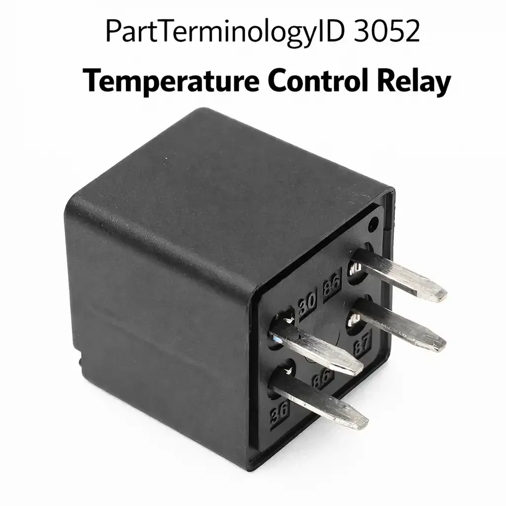
Temperature Control Relay (PartTerminologyID 3052): Where System Identification and Contact Configuration Determine Correct Fitment Across Six Distinct Heating Applications
Written by Arthur Simitian | PartsAdvisory
PartTerminologyID 3052, Temperature Control Relay, is the relay that switches power to a temperature-dependent load such as an engine coolant heater, a battery heater, a seat heater element, a mirror heater, a windshield defroster element, or a climate control system component under the command of a temperature control module, thermostat circuit, or BCM output based on a monitored temperature signal. That definition covers the temperature-controlled circuit switching function correctly and leaves unresolved which specific temperature-controlled load the relay serves since multiple very different vehicle systems use a relay described as a temperature control relay, the temperature sensor or thermostat that commands the relay, the activation threshold temperature and whether it is a fixed thermostat threshold or a programmable module-controlled value, the contact current rating for the specific heated element or motor load, and whether the relay is a normally-open contact that closes on heat demand or a normally-closed contact that opens on overtemperature protection.
For sellers, PartTerminologyID 3052 is the relay PartTerminologyID with the widest system scope of any in this series, because temperature control relay describes a relay used in at least six distinct vehicle systems: engine block heater circuits, battery thermal management systems, heated seat elements, heated mirror circuits, rear window defroster circuits, and HVAC climate control actuator circuits. Each of these systems operates at a different current level, activates from a different temperature sensor, and uses a different relay specification. A listing that covers any of these under the PartTerminologyID 3052 label without clearly identifying the specific system served is unverifiable by any buyer who knows which system is faulted on their vehicle.
What the Temperature Control Relay Does
System identification as the mandatory first attribute
The temperature control relay's function is defined by the system it serves, not by the relay's internal electrical characteristics alone. The engine block heater temperature control relay switches a 120-volt AC circuit on some truck applications and is not an automotive DC relay at all. The battery heater relay on hybrid and electric vehicles switches a low-voltage DC heating mat circuit. The heated seat relay switches a 12-volt DC heating element that draws 4 to 8 amperes per zone. The rear defroster relay switches a heating grid that draws 15 to 25 amperes. The HVAC temperature control relay in an electric vehicle climate control system may switch a 400-volt high-voltage circuit. These are four completely different relay specifications that share only the PartTerminologyID 3052 label.
Every listing under PartTerminologyID 3052 must identify the specific system served in the title as the first attribute before year, make, model, or any other specification. A buyer who searches for a temperature control relay and receives a rear defroster relay when they needed a battery heater relay has received a part that is completely incompatible with their application despite correct PartTerminologyID matching. System identification is not a descriptive refinement for this PartTerminologyID. It is the foundational matching attribute without which no fitment claim is verifiable.
Activation threshold and the normally-open versus normally-closed contact logic
Temperature control relays operate in two contact logic configurations depending on whether they activate heating loads or provide overtemperature protection. A normally-open relay in a heating application closes when the temperature sensor reports a temperature below the heating activation threshold, energizing the heater element or motor. It opens when the temperature rises above the setpoint, de-energizing the load. A normally-closed relay in an overtemperature protection application holds the load energized during normal operation and opens the contact only when the temperature exceeds the protection threshold, de-energizing the load as a protective action.
Confusing normally-open and normally-closed contact logic when replacing a temperature control relay produces the opposite of the desired behavior: a heating relay replaced with a normally-closed unit activates the heater continuously rather than on demand, and a protection relay replaced with a normally-open unit leaves the protected load unprotected by de-energizing it at activation threshold rather than at the overtemperature threshold. The normally-open versus normally-closed contact configuration must be stated as a mandatory attribute for every temperature control relay listing and must be verified against the original relay's contact marking before installation.
Thermostat-controlled versus module-controlled relay activation
Temperature control relays are activated either by a simple thermostat that switches the relay coil directly when a bimetallic element reaches its set temperature, or by a temperature control module that receives a sensor signal, compares it to a programmed threshold, and commands the relay through a module output driver. Thermostat-controlled relays require only correct coil voltage and contact rating matching. Module-controlled relays also require coil resistance within the module's driver output tolerance. A thermostat-controlled rear defroster timer relay is replaced differently from a BCM-controlled rear defroster relay, even though both switch the same defroster grid element in the same vehicle.
Why This Part Generates Returns
Buyers return temperature control relays because the system served is not identified in the listing and a rear defroster relay is delivered for a heated seat application whose current rating, contact configuration, and activation threshold are completely different, the normally-closed protection relay is delivered for a normally-open heating application causing the heated element to run continuously, the BCM-controlled relay coil resistance is outside the module's driver tolerance generating a relay circuit fault while the temperature control system remains inoperative, the thermostat set temperature in the replacement differs from the original causing the heater element to activate at the wrong temperature threshold, and the HVAC application requires a relay rated for a hybrid high-voltage circuit and a standard 12-volt DC relay is delivered.
Why Catalog Data Quality Matters for PartTerminologyID 3052
The high-voltage application note under this PartTerminologyID carries a safety dimension that the other temperature control relay attributes do not. A wrong-system relay or a wrong-configuration relay produces a non-functional or incorrectly-functioning heater circuit. These are inconveniences. A standard 12-volt relay installed in a high-voltage HVAC circuit on a hybrid or electric vehicle is a potential insulation failure that can create a shock hazard from the high-voltage circuit inside the vehicle cabin. The voltage system attribute for high-voltage applications is a safety attribute, not a specification refinement, and must be treated with the same mandatory status as architecture identification for safety-critical relays in this series.
Status in New Databases
PIES/PCdb: PartTerminologyID 3052, Temperature Control Relay
PIES 8.0 / PCdb 2.0: No change.
Top Return Scenarios
Scenario 1: "Wrong system, rear defroster relay for heated seat application"
The buyer needs a heated seat temperature control relay. The listing covers temperature control relays without system identification. The delivered relay is the rear defroster unit with a 20-amp contact rating. The heated seat circuit requires a 6-amp relay with a different thermostat threshold. The relay physically fits the socket but overdrives the seat heater element.
Prevention language: "System served: [heated seat / rear defroster / mirror heater / battery heater / block heater / HVAC]. This relay covers the [system]. Verify the specific temperature control system before ordering. Temperature control relays for different systems are not interchangeable despite sharing the same PartTerminologyID."
Scenario 2: "Normally-closed protection relay for normally-open heating application, heater runs continuously"
The replacement relay has a normally-closed contact. The original was normally-open. The heated element activates immediately at ignition-on and runs continuously regardless of temperature. The element overheats.
Prevention language: "Contact configuration: [normally open, closes on heat demand / normally closed, opens on overtemperature]. Verify the contact configuration matches the original relay's marking before installation. Reversed contact logic causes continuous heater activation or complete heater deactivation depending on the direction of the mismatch."
Scenario 3: "Coil resistance out of BCM tolerance, relay circuit fault code stored after installation"
The buyer installs the replacement temperature control relay. The system remains inoperative and the BCM stores a relay circuit fault code. The BCM monitors coil current through the relay driver output and compares the measured current against a programmed threshold. The replacement relay's coil resistance differs from the original's specification enough that the BCM's measured coil current falls outside the acceptable monitoring window. The BCM flags a relay circuit fault and inhibits the temperature control output rather than risk operating with an unmonitored relay.
Prevention language: "Coil resistance: [X] ohms. BCM-controlled temperature relays are monitored for coil current draw. A replacement with coil resistance outside the BCM's tolerance window generates a relay fault code even when the relay is electrically functional. Verify the coil resistance matches the OEM specification before ordering."
Scenario 4: "High-voltage HVAC relay ordered, standard 12V relay delivered, voltage rating exceeded"
On hybrid and electric vehicle auxiliary heating applications, the temperature control relay switches a high-voltage AC or DC heating element in the cabin heater circuit. The buyer orders a temperature control relay. The listing does not specify voltage system. A standard 12-volt DC relay is delivered. The voltage insulation rating of the standard relay is inadequate for the high-voltage circuit. The relay arcs internally and fails immediately on contact with the high-voltage circuit, and may represent a safety hazard from a single failure mode in the high-voltage isolation.
Prevention language: "Voltage system: [12V DC / High Voltage HV circuit]. This relay is rated for the [voltage system]. High-voltage HVAC relays on hybrid and electric vehicles require HV-rated isolation and contact specifications. A standard 12V relay must not be used in a high-voltage circuit under any circumstance."
PartTerminologyID: 3052
system served: heated seat, rear defroster, mirror heater, battery heater, block heater, or HVAC (mandatory, in title)
contact configuration: normally open or normally closed (mandatory)
activation threshold temperature or module-controlled (mandatory)
contact current rating for specific element or motor load (mandatory)
coil resistance for module-controlled applications (mandatory)
voltage system: 12-volt DC or high-voltage note for hybrid applications (mandatory)
OEM part number cross-reference (mandatory)
Listing Requirements
PartTerminologyID: 3052
system served: heated seat, rear defroster, mirror heater, battery heater, block heater, or HVAC (mandatory, in title)
contact configuration: normally open or normally closed (mandatory)
contact current rating appropriate to system load (mandatory)
thermostat set temperature where relay incorporates thermostat (mandatory)
voltage system: 12V DC or high-voltage HV circuit (mandatory)
coil resistance within BCM or module driver tolerance (mandatory for module-controlled)
OEM part number cross-reference (mandatory)
Catalog Checklist for ACES/PIES Teams
PartTerminologyID = 3052
require system identification in title (mandatory)
require contact configuration: NO or NC (mandatory)
require contact current rating appropriate to system (mandatory)
require voltage system: 12V or HV (mandatory)
prevent system mismatch: rear defroster relay in heated seat application overdrives seat element; system identification in title is non-negotiable matching attribute
prevent contact logic reversal: NC relay in NO application runs heater continuously; contact configuration is a primary matching attribute, not a secondary specification
prevent high-voltage relay substitution: standard 12V relay in HV circuit represents insulation failure risk; voltage system must be specified and matched before any other attribute
FAQ (Buyer Language)
How do I know if my temperature control relay is normally open or normally closed?
Check the original relay body for contact marking: NO indicates normally open, NC indicates normally closed. If the marking is absent, measure continuity between the contact terminals with the coil de-energized. Continuity in the de-energized state indicates normally closed. No continuity indicates normally open.
Why does my heater run continuously after relay replacement?
A normally-closed relay was installed in place of a normally-open relay. The closed contact activates the load whenever the coil is de-energized, which is the opposite of the intended behavior. Replace with a normally-open relay whose contact opens when de-energized.
What symptom does a failed-open temperature control relay produce?
A failed-open relay prevents the heating element from activating at all. Heated seats produce no warmth. Rear defogger produces no heating grid activation. Heated mirrors remain cold. The element can be tested by applying 12-volt power directly to the element supply terminals to confirm the element itself is functional before the relay is condemned as the fault source.
Can one temperature control relay cover multiple heated zones?
On some vehicles, a single relay supplies power to all heated seat zones and the steering wheel heater simultaneously. On others, each zone has its own relay. The listing must identify how many zones the relay serves, because a single shared relay failure will silence all zones at once, while individual zone relays produce single-zone failures that appear as element faults until the relay is tested.
Why is the thermostat temperature threshold listed as a mandatory attribute?
Temperature control relays that incorporate a thermostat, such as block heater relays and battery heater relays, activate at a specific ambient temperature threshold. A replacement with a different threshold will activate the heater at the wrong temperature: too warm means the heater never activates in the relevant climate, too cold means the heater activates at temperatures where it is unnecessary. The threshold must match the original specification for the vehicle's climate rating.
Cross-Sell Logic
Heated Seat Element: for buyers where the relay is confirmed delivering voltage to the element terminals but no heat is produced, indicating a failed heating element rather than a relay fault
Rear Window Defogger Switch: for buyers where the defroster relay receives no activation signal, indicating a switch fault before the relay in the control circuit
Heated Mirror Element: for vehicles where the mirror heating and rear defogger share a single temperature control relay, and mirror heating failure accompanies defogger failure
Temperature Control Module: for BCM-integrated applications where the relay coil activation signal is absent, indicating a module output driver fault rather than a relay fault
What Sellers Get Wrong About PartTerminologyID 3052
The most common error under PartTerminologyID 3052 is listing the relay without identifying the system served. Temperature control is a generic description that applies equally to a heated seat relay drawing 6 amperes, a rear window defogger relay drawing 20 amperes, a battery heater relay with a thermostatic activation threshold, a block heater relay with a different threshold, and a hybrid vehicle auxiliary heater relay operating at high voltage. All six are listed as temperature control relays. A listing that specifies only year, make, and model without naming the specific heating system cannot be matched by any buyer who knows their symptom is in the heated seat and not the defroster. System identification is the foundational matching attribute, and its absence from the listing title makes every other specification in the listing evaluable only after the buyer guesses which system the listing covers.
The second most common error is treating contact configuration as a secondary specification. It is not. Normally-open and normally-closed contacts are opposite logic states. The wrong configuration does not produce a non-functional result that is easily identified during installation. It produces the opposite result: a normally-closed relay installed in a normally-open application activates the load immediately at ignition-on and runs it continuously. The seat element overheats. The defroster grid overheats. The battery heater activates continuously in warm weather, degrading battery performance. None of these failure modes produce an immediately obvious installation error signal. The error only manifests as a symptom that appears after the relay has been operating for a period of time in the wrong logic state.
The third error, specific to modern BCM-controlled applications, is omitting the coil resistance specification. BCM output driver circuits monitor relay coil current continuously. A replacement relay with coil resistance outside the BCM's acceptable monitoring window generates a relay circuit fault code immediately after installation and inhibits the BCM from activating the relay output. The symptom is indistinguishable from a relay failure: the system remains inoperative and the BCM reports a relay circuit fault. The coil resistance specification must be confirmed against the OEM relay specification before any BCM-controlled temperature relay listing is published.
Final Take for PartTerminologyID 3052
Temperature Control Relay (PartTerminologyID 3052) is the relay PartTerminologyID with the widest system scope in this series. System identification in the title is not optional. Contact configuration is not a secondary specification. Both are primary matching attributes that must be stated before any other relay specification, because the wrong system relay and the wrong contact configuration produce results that range from non-functional to continuously-on overheating elements. A normally-closed relay in a normally-open heated seat application will heat the seat element from the moment the ignition turns on, with no response to the seat heat switch, until the element overheats or the fuse blows. A normally-open relay in a normally-closed protection application will allow the protected element to run unprotected, eliminating the thermal runaway protection that the relay was installed to provide. System identification prevents the relay from arriving in the wrong application. Contact configuration prevents the relay from operating in the opposite logic from what the circuit requires. Thermostat threshold, where applicable, prevents the relay from activating at the wrong ambient temperature. All three must be present before any fitment claim is accurate.
The high-voltage application note requires particular attention because its consequences are not limited to a non-functional component. A standard 12-volt relay installed in a high-voltage auxiliary heater circuit on a hybrid or electric vehicle operates outside its insulation rating from the first moment of activation. The relay's internal insulation was designed to withstand 12-volt DC working voltage with appropriate safety margins. A high-voltage AC or DC heater circuit may present 200 to 400 volts across the relay's contact gap when open. This voltage exceeds the 12-volt relay's insulation clearance rating and can result in arc-over inside the relay housing. The listing must state the voltage system for every temperature control relay application, and the high-voltage designation must be treated as a disqualifying mismatch for any standard 12-volt relay, regardless of contact current rating, physical size, or any other specification that might otherwise appear compatible.