ABS Relay (PartTerminologyID 3008): Where Single Versus Multi-Relay Architecture and Combined Current Rating Determine Whether ABS System Power Is Correctly Restored
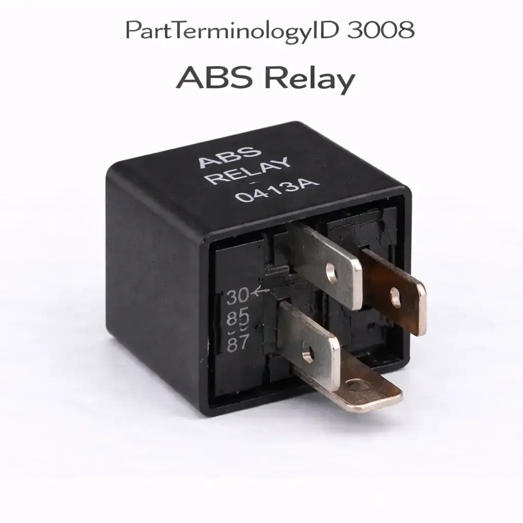
Written by Arthur Simitian | PartsAdvisory
PartTerminologyID 3008, ABS Relay, is the primary power supply relay for the anti-lock braking system as a whole, providing switched battery voltage to the ABS control module and enabling the module to perform its self-diagnostic and to command the modulator and pump relay circuits during normal and ABS braking operation. That definition covers the ABS system primary power relay function correctly and leaves unresolved whether the vehicle uses a single combined ABS relay covering both the module power supply and the hydraulic circuit control, or separate relays for the module power, the modulator solenoids, and the pump motor as covered by PartTerminologyIDs 2988 and 2992, the contact current rating for the combined ABS system load if this is a single combined relay, and the distinction between this primary ABS relay and the system-specific component relays when the vehicle uses a multi-relay ABS architecture.
For sellers, PartTerminologyID 3008 is the ABS relay PartTerminologyID that most frequently generates architectural confusion in the catalog because some vehicles route all ABS power through a single relay covered by PartTerminologyID 3008, while others segregate ABS power into separate modulator, pump, and module supply relays covered by separate PartTerminologyIDs. A buyer whose vehicle uses a single combined ABS relay who is directed to PartTerminologyID 2988 or 2992 will order a modulator or pump relay that does not exist as a separate component on their vehicle. Conversely, a buyer whose vehicle uses separate component relays who orders under PartTerminologyID 3008 may receive a combined relay that cannot be installed because the vehicle's relay center has separate sockets for each ABS relay function.
What the ABS Relay Does
Single combined relay architecture
On vehicles using a single ABS relay, this relay switches battery voltage to all ABS system consumers simultaneously: the ABS control module, the modulator solenoid circuits, and the pump motor circuit all receive power through the same relay contact. When the relay fails, all ABS functions are disabled simultaneously and the ABS warning light illuminates. The single-relay architecture simplifies the replacement decision because a single relay diagnosis and replacement restores all ABS system power. The relay's contact current rating must accommodate the worst-case simultaneous load of module supply current plus all solenoid currents plus pump motor startup inrush, making the combined ABS relay one of the highest current-rated ISO relays in the vehicle's fuse center.
Multi-relay architecture and routing to component PartTerminologyIDs
On vehicles with separate ABS relays the relay covered by PartTerminologyID 3008 may be the ABS control module power supply relay only, with the modulator and pump loads served by their own relays at PartTerminologyIDs 2988 and 2992. In this architecture a failed ABS module supply relay prevents the module from powering up and illuminates the ABS warning light, but the modulator and pump hardware could be independently functional. The buyer ordering under PartTerminologyID 3008 for a multi-relay vehicle must be directed to the specific relay that the ABS scan tool fault code identifies as the faulted circuit, because the module supply, modulator, and pump relay fault codes are distinct.
Safety and post-replacement verification
The ABS relay is safety-critical because its failure disables the anti-lock braking system entirely, reverting the vehicle to conventional braking without wheel speed monitoring. On wet or icy roads, loss of ABS significantly increases stopping distances and the risk of wheel lockup and loss of directional control during emergency braking. The listing must state that the vehicle should not be operated in conditions where ABS activation is likely until the relay is replaced and the ABS system is confirmed functional by scan tool verification. Post-replacement scan tool check is mandatory to confirm the ABS module powers up, performs its self-test successfully, and stores no fault codes before the vehicle is returned to service.
Diagnosing the ABS relay before replacement
The ABS relay can be tested in the fuse center socket without specialized tools. With the relay removed, check for battery voltage at the relay socket's contact supply terminal with the ignition on. Absent supply voltage at this terminal indicates a blown fuse or an open circuit upstream of the relay socket, not a relay failure. If supply voltage is present, check for coil activation voltage at the relay socket's coil terminals. On most vehicles the ABS module or BCM supplies a ground path to the coil negative terminal when commanded on. If no coil voltage appears, the module or BCM is not commanding relay activation, and the fault is upstream in the module's output logic. If supply voltage and coil activation voltage are both present at the socket, the relay is receiving correct inputs and its failure to close indicates an open coil or failed contacts. Substituting a known-good relay of the correct specification at this point confirms whether the relay is the fault or the circuit has an additional problem.
Relay specification and contact current in combined architectures
The combined ABS relay on single-relay architecture vehicles carries a higher contact current than most other ISO relays in the vehicle's fuse center. A standard 30-amp ISO relay is not necessarily sufficient for this application. The ABS module supply current alone may be 2 to 5 amperes at steady state. Four modulator solenoids at 1 to 2 amperes each add 4 to 8 amperes. The pump motor startup inrush at 15 to 30 amperes occurs briefly at each ABS activation event. The relay's contact rating must be evaluated against the worst-case combined load including pump motor inrush, not against the steady-state module supply current alone. Undersizing this relay is the cause of the ABS relay contact failure scenario where the relay appears to operate normally during non-ABS driving but fails during the first ABS activation event that applies the full combined load.
Why This Part Generates Returns
Buyers return ABS relays because the vehicle uses a multi-relay ABS architecture and the combined relay listing does not exist as a separate component on their vehicle, the ABS module supply relay is delivered but the fault is in the modulator relay circuit requiring a PartTerminologyID 2988 replacement, the ABS warning light remains on after relay replacement because a wheel speed sensor or ABS module fault is also present, and the relay contact rating is insufficient for the combined single-relay architecture's simultaneous current load.
Why Catalog Data Quality Matters for PartTerminologyID 3008
The ABS relay is the most safety-critical relay in this series because its failure disables a federally mandated vehicle safety system. Catalog data quality standards for safety-critical components must be higher than for convenience relays. An architecture error that sends a multi-relay vehicle buyer a combined relay costs both parties the return transaction. An architecture error during a panic stop on ice costs more than a transaction. The listing investment for correct architecture identification, correct contact current rating, and post-replacement scan tool verification language is minimal relative to the liability exposure of shipping an undersized relay to a buyer who will never know it is undersized until the ABS event that reveals it.
Status in New Databases
PIES/PCdb: PartTerminologyID 3008, ABS Relay
PIES 8.0 / PCdb 2.0: No change.
Top Return Scenarios
Scenario 1: "Multi-relay vehicle, combined relay ordered, no single relay socket exists"
The buyer orders the combined ABS relay. The vehicle has separate sockets for modulator, pump, and module supply relays. There is no single combined ABS relay socket in the relay center. The delivered relay cannot be installed.
Prevention language: "ABS relay architecture: [single combined relay / separate module, modulator, and pump relays]. This listing covers the [architecture]. Verify whether the vehicle uses a single combined ABS relay or separate component relays before ordering. Multi-relay vehicles require the specific component relay identified by ABS scan tool fault code."
Scenario 2: "ABS light still on, wheel speed sensor fault, relay was not the cause"
The buyer replaces the ABS relay for an ABS warning light. The light remains on. A rear wheel speed sensor has an intermittent signal fault that was the actual cause of the ABS warning light. The relay was functional. The replacement relay resolves nothing.
Prevention language: "Diagnostic note: Confirm the ABS scan tool fault code points to the relay power supply circuit before ordering. Wheel speed sensor faults, ABS module faults, and hydraulic circuit faults all illuminate the ABS warning light independently of relay status."
Listing Requirements
PartTerminologyID: 3008
ABS relay architecture: single combined or separate component relays (mandatory)
contact current rating for combined load (mandatory for single-relay architecture)
circuit covered: module supply, combined module and hydraulics, or system-level (mandatory)
safety criticality: ABS disabled at relay failure (mandatory)
post-replacement ABS scan verification (mandatory)
routing note to PartTerminologyIDs 2988 and 2992 for multi-relay vehicles (mandatory)
OEM part number cross-reference (mandatory)
Catalog Checklist for ACES/PIES Teams
PartTerminologyID = 3008
require ABS relay architecture: single combined or multi-relay (mandatory)
require contact current rating appropriate to architecture (mandatory)
require safety criticality disclosure (mandatory)
require post-replacement scan tool verification note (mandatory)
prevent combined relay listing on multi-relay vehicle: buyer receives relay with no socket to install; architecture is a required matching attribute before any fitment claim is published
prevent relay replacement without scan tool diagnosis: wheel speed sensor faults and ABS module faults illuminate the same warning light as relay faults; a relay replaced without scan tool confirmation may be the correct part for the wrong fault
differentiate from ABS Modulator Relay (2988): 3008 covers the system primary power supply or combined system relay; 2988 covers the modulator solenoid circuit relay specifically on multi-relay architectures
differentiate from ABS Pump and Motor Relay (2992): 3008 covers the system primary power supply or combined system relay; 2992 covers the hydraulic pump motor circuit relay specifically on multi-relay architectures
FAQ (Buyer Language)
Is the ABS relay the same as the ABS modulator relay?
On single-relay vehicles yes, one relay powers the entire ABS system. On multi-relay vehicles no, the ABS relay powers the module supply while separate relays power the modulator solenoids and pump motor. Verify which architecture the vehicle uses before ordering.
Can I drive with a failed ABS relay?
The brakes function normally for non-ABS stops. ABS is disabled. On slippery roads or during emergency stops, wheel lockup is possible without the ABS modulation that would otherwise prevent it. Replace the relay before operating the vehicle in conditions where ABS would normally activate.
Will replacing the ABS relay clear the ABS warning light?
Only if the relay was the sole cause of the warning light. The ABS module illuminates the warning light for any fault it detects, including wheel speed sensor faults, hydraulic circuit faults, and module internal faults, not only for relay power supply failures. After relay replacement, use an ABS-capable scan tool to read the module's current fault codes. If additional codes are present, those faults must be resolved before the warning light will extinguish and the ABS system will operate correctly.
How do I identify whether my vehicle uses a single or multi-relay ABS architecture?
Inspect the vehicle's fuse and relay center diagram, typically printed on the inside cover of the fuse box lid or available in the owner's manual. Look for relay positions labeled ABS relay, ABS pump relay, and ABS modulator relay. If three separate labeled positions exist, the vehicle uses multi-relay architecture. If only one ABS relay position exists, the vehicle uses single combined relay architecture. The VIN-specific fuse center diagram is the authoritative source.
Cross-Sell Logic
ABS Modulator Relay (PartTerminologyID 2988): for multi-relay architecture vehicles where the scan tool fault code identifies the modulator solenoid circuit rather than the module supply circuit as the faulted relay position
ABS Pump and Motor Relay (PartTerminologyID 2992): for multi-relay architecture vehicles where the scan tool fault code identifies the hydraulic pump motor circuit relay as the faulted component
ABS Control Module: for vehicles where the relay is confirmed functional but the ABS module fails to power up or complete its self-test after relay replacement, indicating a module internal fault
Wheel Speed Sensor: for vehicles where the ABS warning light remains on after relay replacement and the scan tool stores a wheel speed sensor fault code that was the actual cause of the warning light
What Sellers Get Wrong About PartTerminologyID 3008
The most common catalog error under PartTerminologyID 3008 is publishing a single ABS relay listing that covers every vehicle in the make and model range without distinguishing architecture. A three-year model run of the same vehicle may have started production with a single combined ABS relay and transitioned to a multi-relay architecture at a mid-cycle revision. Both architecture types exist under the same model year range, and the fuse center layout is the only reliable way to determine which architecture a specific vehicle uses. A catalog that treats the entire model range as single-architecture will deliver the wrong component to every buyer with the post-revision multi-relay vehicle.
The second most common error is listing the ABS relay without a contact current rating. A standard ISO relay is available in 20-amp, 30-amp, and 40-amp contact ratings, and they physically fit the same socket. A buyer who orders the relay based on year, make, and model alone may receive a 20-amp relay for a combined ABS relay application that requires 35 amperes under peak combined load. The relay passes the bench test, passes the self-test activation, and fails during the first genuine ABS braking event. Contact current rating is not a supplemental specification for this PartTerminologyID. It is a safety-critical primary attribute.
The third error is omitting the scan tool requirement from the listing. Post-replacement scan tool verification is standard practice in any brake system repair and must be stated explicitly in the listing because a buyer without scan tool access may return a vehicle to service believing the ABS system is restored when the module has stored additional fault codes that prevent correct ABS operation. The warning lamp may not illuminate for these secondary faults depending on the fault code's illumination trigger logic, and the driver would have no indication that ABS is still not fully operational.
Final Take for PartTerminologyID 3008
ABS Relay (PartTerminologyID 3008) is the ABS system primary relay where single versus multi-relay architecture identification is the mandatory first verification, safety criticality disclosure is mandatory, and post-replacement scan tool confirmation is required before the vehicle is returned to service. The architecture question determines whether a single relay or three separate relays serve the ABS system on the vehicle. Getting it wrong means the buyer receives a component with no socket to install it into on a multi-relay vehicle, or a component that covers only one of three relay positions on a single-relay vehicle. Neither outcome restores ABS function. The safety criticality note prevents the vehicle from being returned to service after relay replacement without scan tool confirmation that the ABS module powers up and clears its self-test. A relay that is replaced but whose circuit has an additional fault from a failed ABS module or a corroded harness connector will not restore ABS warning lamp behavior, and the driver must not assume the ABS system is functional because the lamp behavior has not changed. The scan tool provides the only reliable confirmation of ABS system operational status after any relay replacement under this PartTerminologyID.
The contact current rating for single combined relay architectures is not a refinement that can be inferred from ISO relay standards. A 30-amp ISO relay is not automatically correct for a combined ABS relay position. The combined current requirement under peak ABS activation must be calculated from the specific vehicle's ABS system component loads, and that calculated requirement must be stated in the listing. A buyer who selects any 30-amp relay that fits the socket physically has no guarantee the contact rating is appropriate for the peak combined load on this specific application. The listing must do the specification work before the buyer is asked to verify fitment.
Scenario 3: "Contact rating insufficient for combined load, relay fails under simultaneous ABS activation"
On a single-relay architecture vehicle, the replacement relay has a 20-amp contact rating. The combined ABS system load during a full ABS braking event, including module supply, all four modulator solenoids, and pump motor inrush, peaks at 35 amperes. The relay operates normally during self-test and routine driving because the full load is never applied simultaneously outside of an ABS event. During the first emergency stop that triggers full ABS activation, the relay contact fails under the combined load. The vehicle reverts to conventional braking mid-stop.
Prevention language: "Contact current rating: [X] amperes continuous, [Y] amperes inrush. This relay is rated for the simultaneous combined load of ABS module supply, modulator solenoid circuit, and pump motor inrush. Verify the contact current rating meets or exceeds the OEM specification for single-relay ABS architectures before ordering."
Sellers who invest the 15 minutes required to correctly specify architecture, contact current rating, and post-replacement scan tool verification language for PartTerminologyID 3008 recover that investment on the first prevented return. The return rate reduction from correct architecture identification alone is measurable because the wrong-architecture return is 100 percent preventable and 100 percent attributable to the missing attribute. Every listing published without architecture identification will generate returns from multi-relay vehicle buyers in every order cycle until the attribute is added.
Every ABS relay listing that reaches a buyer with complete architecture, current rating, and scan verification guidance is a return prevented before it begins.