ABS Pump and Motor Relay (PartTerminologyID 2992): Where Motor Inrush Rating and Back-EMF Suppression Determine Whether the Relay Survives ABS Pump Motor Switching
Written by Arthur Simitian | PartsAdvisory
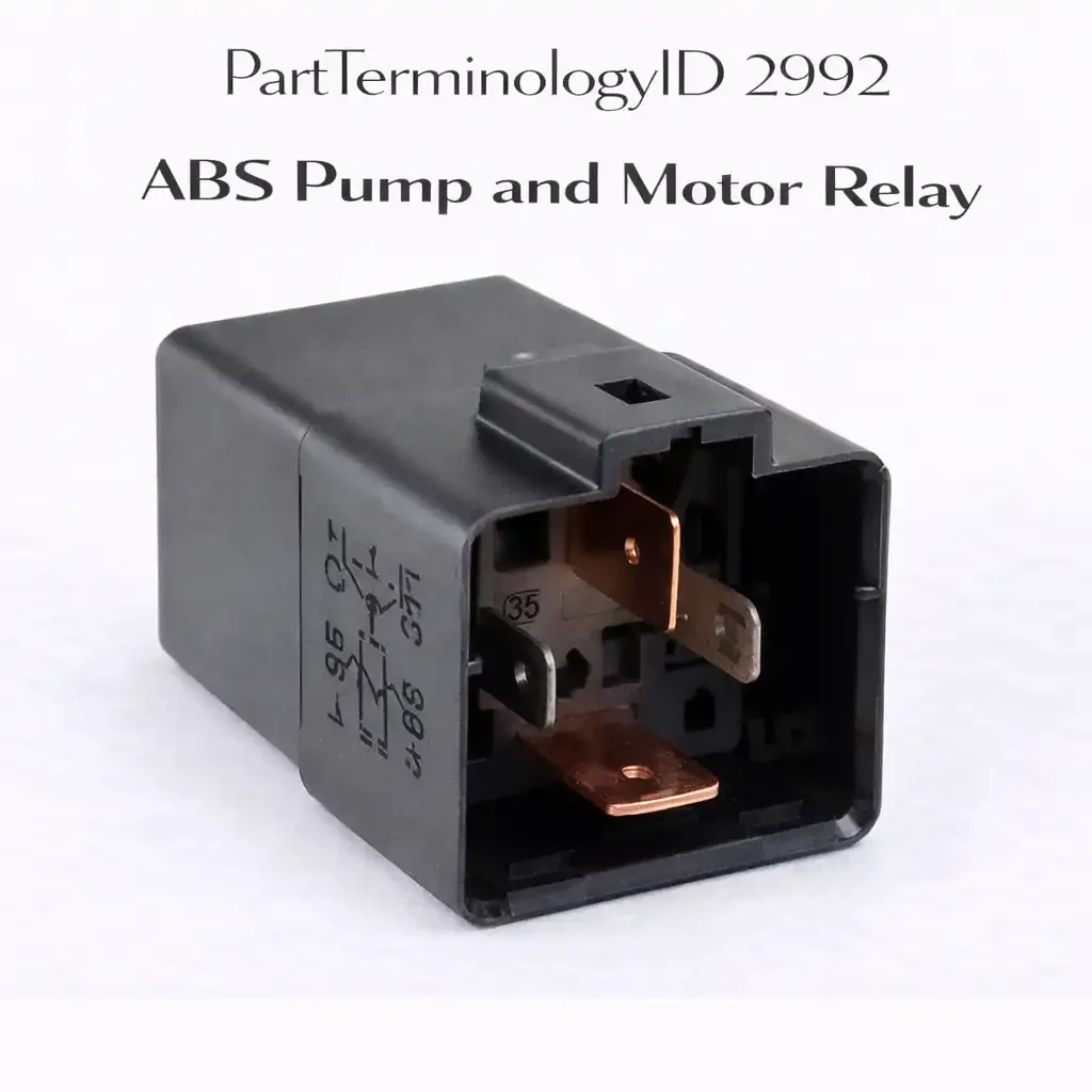
PartTerminologyID 2992, ABS Pump and Motor Relay, is the relay that switches battery voltage to the ABS hydraulic pump motor, enabling the ABS control module to command fluid replenishment in the HCU accumulator during an ABS braking event when the modulator solenoids have released hydraulic pressure from the wheel circuits and the pump must rebuild system pressure for subsequent pressure reapplication cycles. That definition covers the pump motor power switching function correctly and leaves unresolved the contact current rating relative to the pump motor's start-up inrush current which is substantially higher than the solenoid relay's load, whether the pump relay is a separate component from the modulator relay or combined in a single relay assembly, the back-EMF suppression requirement from the motor circuit, and the relay's mounting location on the HCU body versus the underhood relay center.
For sellers, PartTerminologyID 2992 is the ABS relay PartTerminologyID with the highest contact current requirement of the ABS relay set because the pump motor draws significantly more current at startup than the modulator solenoids. ABS pump motors typically draw 15 to 40 amperes at startup depending on the system design. A relay with a contact rating below the motor inrush may hold closed during normal solenoid operation but fail to close cleanly under motor startup current, producing pump motor activation delays that extend the ABS pressure recovery interval and reduce ABS modulation frequency during sustained ABS events.
What the ABS Pump and Motor Relay Does
During an ABS event the modulator solenoids release hydraulic pressure from the wheel circuits to allow the locked wheel to rotate freely. After the pressure release phase the ABS module commands the pump motor to draw the released fluid from the low-pressure accumulator and return it to the master cylinder side of the circuit, rebuilding the pressure reservoir for the next pressure reapplication phase. This pump cycle repeats several times per second during a sustained ABS event on a slippery surface.
The pump motor relay must close and open reliably at this rapid cycling rate. A relay with contact erosion from back-EMF arc damage may close slowly or incompletely, introducing resistance into the motor supply circuit that reduces motor speed and fluid return rate. Reduced fluid return rate limits how quickly the modulator can reapply brake pressure after a release phase, reducing the modulation frequency below specification and producing a less effective ABS response. The listing must specify the contact current rating for motor inrush and must note whether back-EMF suppression is integrated into the relay or provided by the motor circuit.
Pump motor activation frequency and contact erosion rate
The ABS pump motor relay cycles on and off many times per second during sustained ABS events on slippery surfaces. Each relay opening event generates a back-EMF arc from the motor coil's stored magnetic energy collapsing across the contact gap. A relay without back-EMF suppression accumulates arc damage at a rate proportional to the number of ABS events and the duration of each event. A vehicle operated frequently in wet or icy conditions where ABS activates on many stops will accumulate relay contact erosion faster than a vehicle in dry climates where ABS rarely activates. Contact life depends as much on operating environment as on the relay's initial contact quality.
Back-EMF suppression and pump motor relay longevity
The pump motor relay must handle the motor's back-EMF voltage spike at each de-energization event. A pump motor operating at 12 volts generates a back-EMF spike at relay opening that can reach 60 to 100 volts momentarily as the motor's rotating armature continues to generate voltage after the relay contact opens. This spike arcs across the contact gap, eroding both contact surfaces with each event. A replacement relay with integrated back-EMF suppression clamps this spike to a voltage just above the supply voltage, eliminating the arc and extending contact life significantly across the relay's operating lifetime. The original relay's back-EMF suppression architecture must be maintained in the replacement to preserve the contact life design intent.
Pump motor inrush current and the relay contact stress profile
The ABS pump motor starts from rest at every ABS event, drawing locked-rotor inrush current for the first 50 to 150 milliseconds until the armature reaches operating speed and back-EMF builds to reduce the current draw toward the running value. The inrush current is typically two to four times the running current. A pump motor drawing 15 amperes at running speed may draw 30 to 45 amperes for the first 100 milliseconds of each ABS activation. The relay contact must handle this inrush without arc damage or contact welding on every ABS cycle. Relay manufacturers specify both a continuous current rating and a make current rating, and the make current rating must exceed the pump motor's inrush to prevent contact damage at the moment of relay closure on each ABS event.
Integrated ABS unit architecture and the relay location question
On integrated ABS units where the hydraulic control unit, electronic control unit, and pump motor are combined into a single assembly, the pump relay may be located inside the ABS unit housing rather than in the vehicle's main fuse center. A buyer who searches the fuse center for the ABS pump relay and finds no relay socket may have a vehicle with an integrated unit where the relay is internal to the ABS assembly. Replacing an internal relay on an integrated unit typically requires ABS unit disassembly or replacement of the hydraulic control unit with a remanufactured assembly that includes the relay. Confirming the pump relay's location before ordering prevents ordering an external relay for a vehicle with an internally-mounted relay.
Why This Part Generates Returns
Buyers return ABS pump and motor relays because the contact current rating is sized for the modulator solenoid load and is insufficient for the pump motor inrush, the relay is combined with the modulator relay in a single assembly and the listing covers only the pump function, and the pump motor itself has failed and the relay replacement does not restore pump operation because the motor is the actual failed component.
Status in New Databases
PIES/PCdb: PartTerminologyID 2992, ABS Pump and Motor Relay
PIES 8.0 / PCdb 2.0: No change.
Listing Requirements
PartTerminologyID: 2992
contact current rating: continuous and motor inrush (mandatory)
back-EMF suppression: integrated or external (mandatory)
standalone versus combined with modulator relay (mandatory)
pump motor fault diagnosis note: confirm motor operates before relay replacement (mandatory)
safety criticality note (mandatory)
OEM part number cross-reference (mandatory)
FAQ (Buyer Language)
What is the difference between the ABS modulator relay and the pump relay?
The modulator relay powers the solenoid valves that release and hold wheel brake pressure. The pump relay powers the motor that rebuilds system pressure after a pressure release event. Both are required for correct ABS function. Both must be verified when diagnosing ABS system faults.
Why must the pump relay handle more current than the modulator relay?
The pump motor draws 15 to 40 amperes at startup versus 3 to 8 amperes for the combined solenoid load. A relay sized for solenoid current cannot handle motor inrush without contact stress and eventual failure.
How do I confirm the pump motor is running after relay replacement?
After relay replacement, connect a scan tool and command ABS pump motor activation through the ABS module's actuator test function if available. Alternatively, during the next ABS activation event observe whether the pedal pulsation is present and the stopping distance is normal. No pedal pulsation during an ABS event that should activate the pump indicates the pump motor is not running. Measure voltage at the pump motor supply terminal during commanded activation to confirm the relay is closing and delivering supply voltage to the motor.
Can the ABS pump relay and the ABS modulator relay be the same component?
On vehicles using a single combined ABS relay covered by PartTerminologyID 3008, yes. The single relay switches power to both the modulator solenoids and the pump motor simultaneously. On vehicles with separate relay architecture, the pump relay and modulator relay are distinct components in separate relay sockets with different current ratings. Confirm the vehicle's ABS relay architecture before ordering to determine whether a single combined relay or separate pump and modulator relays are required.
Top Return Scenarios
Scenario 1: "ABS pump relay replaced, pump still does not run, motor is seized"
The buyer replaces the pump relay. The ABS pump does not activate during an ABS event. Testing confirms the relay contact closes and delivers supply voltage to the pump motor terminal. The motor does not run. The pump motor has seized and requires replacement. The relay was functional. The motor seizure was the original fault and the relay replacement was a misdiagnosis. The buyer returns the relay as defective when the motor is the fault.
Prevention language: "Before installing the replacement relay, apply 12 volts directly to the pump motor supply terminal and confirm the motor runs. A motor that does not run from direct supply has seized and requires replacement regardless of relay condition. Relay replacement will not restore ABS pump function on a seized motor."
Scenario 2: "Relay welds closed within days of installation, motor drawing locked-rotor current"
The buyer installs the replacement relay. The ABS pump runs continuously and cannot be shut off. The replacement relay contact has welded closed from sustained locked-rotor current drawn by a pump motor that is beginning to seize. The original relay failed for the same reason. Without identifying the motor fault before installation, each replacement relay welds closed within the same period as the original.
Prevention language: "Measure pump motor current draw during normal operation before installing the replacement relay. Motor current above specification indicates a bearing fault or rotor drag that produces above-rating current draw. Resolving the motor fault before relay installation prevents the replacement contact from welding closed under the excessive current."
Cross-Sell Logic
ABS Modulator Relay (PartTerminologyID 2988): confirm the modulator relay is functional alongside the pump relay on vehicles with separate relay architecture
ABS Pump Motor: for buyers where the relay is confirmed functional but the pump motor has seized and requires replacement
ABS Module: for buyers where the pump relay coil receives no activation voltage indicating an ABS module output driver fault
Catalog Checklist for ACES/PIES Teams
PartTerminologyID = 2992
require contact current rating for pump motor inrush and running current (mandatory)
require make current rating above pump motor inrush specification: inrush at relay closure may reach two to four times running current for the first 100 to 150 milliseconds of each pump activation event (mandatory)
require back-EMF suppression specification (mandatory)
require relay location: external fuse center or internal to ABS unit (mandatory)
require coil resistance within ABS module driver tolerance (mandatory)
prevent relay order before motor seizure inspection: seized pump motor welds replacement relay contact immediately
differentiate from ABS Modulator Relay PartTerminologyID 2988: pump relay switches motor supply; modulator relay switches solenoid supply; different current requirements
Final Take for PartTerminologyID 2992
ABS Pump and Motor Relay (PartTerminologyID 2992) is the ABS relay with the highest current demand, where motor inrush rating and back-EMF suppression determine whether the relay survives repeated pump motor switching events over the vehicle's service life. A relay sized only for continuous steady-state current without accounting for the pump motor's inrush at each ABS activation cycle will erode contacts progressively through accumulated arc damage until the relay fails open, leaving the ABS system inoperative on the next activation. Back-EMF suppression, inrush rating, and pump motor seizure inspection before installation are the three attributes that define whether the replacement relay will survive its operating environment or fail again within the same service interval.