Alternator Rectifier Set (PartTerminologyID 2920): Where Diode Count, Current Rating, and Exciter Diode Inclusion Determine Whether the Alternator Charges Correctly After Rectifier Replacement
Written by Arthur Simitian | PartsAdvisory
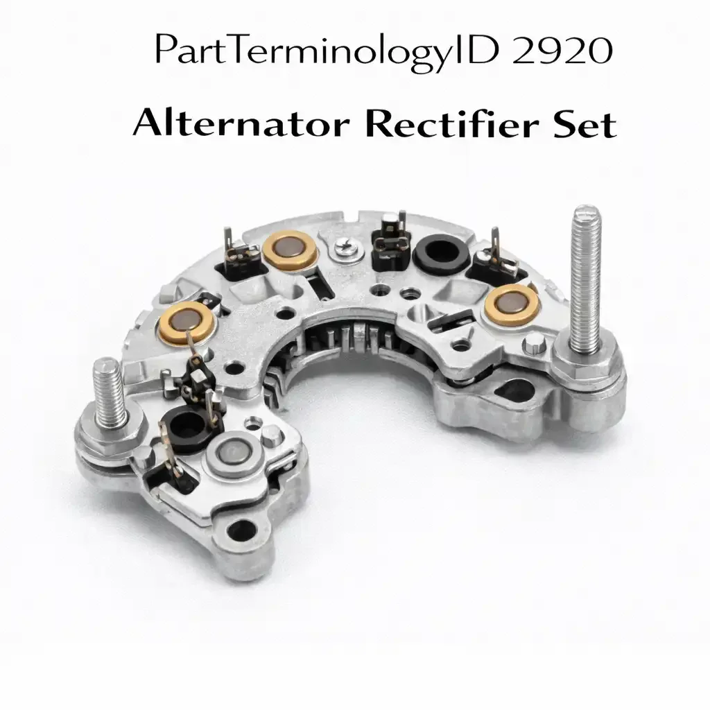
PartTerminologyID 2920, Alternator Rectifier Set, is the diode bridge assembly inside the alternator housing that converts the three-phase alternating current produced by the stator windings into the direct current used to charge the battery and power the vehicle's electrical loads, consisting of a positive and negative heat sink plate each carrying three or six diodes arranged into a full-wave bridge configuration that passes current in the charging direction and blocks reverse current flow from the battery back through the stator. That definition covers the AC-to-DC conversion function correctly and leaves unresolved the alternator model number the rectifier set is designed to fit, the diode count per heat sink plate which distinguishes six-diode from twelve-diode sets used on different alternator output ratings, the per-diode current rating that must meet or exceed the alternator's rated output current, the mounting method which is press-fit for most OEM heat sink assemblies versus bolt-in for many aftermarket service sets, and whether the set includes the exciter diode trio that powers the rotor field winding independently of the battery once the alternator is running.
For sellers, PartTerminologyID 2920 is the charging system internal component PartTerminologyID where the alternator model number is the primary matching attribute above year, make, and model, because the same vehicle platform may have been equipped with two or three different alternator models across its production run depending on the engine option, the electrical load package, and the production date. A rectifier set that fits the 90-amp alternator used on the base engine does not fit the 140-amp alternator used on the towing package or high-electrical-load configuration, even though both are on the same year, make, and model.
What the Alternator Rectifier Set Does
Full-wave bridge rectification and the diode failure signature
The alternator's three-phase stator produces three overlapping sine wave AC outputs offset by 120 degrees from each other. The rectifier set's six positive and six negative diodes, or three positive and three negative on lower-output alternators, sample each phase at its positive and negative peaks respectively and route the combined output to the DC output terminal as a smoothed direct current at the battery charge voltage. Each diode conducts for 120 degrees of the rotation cycle and blocks for the remaining 240 degrees, creating a ripple frequency of six times the alternator shaft frequency that is smoothed by the battery's capacitance effect on the circuit.
When one diode fails open, a single one of the six or twelve conduction intervals per revolution is lost. As a result, the alternator output falls by one sixth or one twelfth of its rated capacity and the ripple frequency shifts from six times to five times the shaft frequency, producing a distinctive whine in the audio system at a pitch that rises and falls with engine RPM. A battery drain test that shows AC ripple above 50 millivolts at the battery terminals with the engine running at about 1,500 RPM reliably confirms a rectifier diode failure. In contrast, a shorted diode produces a direct short from one stator phase to the battery, discharging the battery through the alternator when the engine is off and potentially blowing the alternator fuse or burning out the stator winding.
Exciter diode trio and self-excitation architecture
Many alternator designs, particularly those from Bosch, Denso, and Mitsubishi used across European and Japanese applications, incorporate a separate exciter diode trio mounted on or adjacent to the main rectifier assembly. This trio of smaller diodes taps a small fraction of the AC output from each stator phase and rectifies it to provide the field current that energizes the rotor winding after the alternator reaches sufficient speed to sustain self-excitation. Without the exciter diodes, the alternator requires a continuous external field current supply from the battery through the charge warning light circuit or a dedicated field supply wire to maintain output above the minimum self-sustaining threshold.
A failed exciter diode allows the alternator to produce output initially when the ignition field circuit provides starting excitation, but the output collapses as soon as the vehicle begins operating normally and the starting field circuit transitions to the self-excited state. The symptom is an alternator that charges correctly at startup but progressively drops output over the first five to ten minutes of operation until it stops charging entirely. This symptom pattern specifically points to the exciter diode trio rather than the main rectifier bridge and is important diagnostic information that the listing should include as a cross-reference for buyers identifying their specific failure mode.
Heat sink mounting and installation method
OEM alternator rectifier assemblies typically press-fit the diode elements directly into the heat sink plates using a diode body diameter tolerance that creates an interference fit securing the diode mechanically and electrically. The installation tool for press-fit diodes is a driver that applies force only to the outer diode body rather than the internal semiconductor junction, because applying force to the junction crushes the silicon wafer and destroys the diode. Aftermarket service rectifier sets frequently supply bolt-in diode configurations that thread into the heat sink plate rather than pressing in, avoiding the need for a press installation tool but requiring verification that the bolt-in configuration matches the heat sink plate's thread pattern.
A rectifier set listed as a direct replacement must specify the mounting method so the buyer can confirm they have the correct installation tools before disassembling the alternator. A press-fit rectifier set delivered to a buyer without a diode press tool results in either a damaged new diode from improvised installation or a return of the unopened set after the buyer realizes they cannot install it without the tool. The mounting method and required installation tooling belong in the listing description as practical installation guidance rather than as an afterthought in a separate instruction sheet.
Why This Part Generates Returns
Buyers return alternator rectifier sets because the set fits the 90-amp alternator and the vehicle has the 140-amp unit whose heat sink plate dimensions are larger and whose diode count is higher, the exciter diode trio is not included in the set and the buyer needed a complete assembly with exciter diodes, the press-fit diode set is delivered and the buyer does not have a diode press tool and cannot install it without damaging the new diodes, the replacement diode current rating is below the alternator's rated output and the new diodes run hot under full alternator load, the stator winding was the actual failed component and the AC ripple test that confirmed rectifier failure also indicated stator insulation breakdown that was not caught before the rectifier was replaced, and the listing covers the alternator model number without specifying the production date range and the later-production alternator uses a revised heat sink geometry that is physically incompatible with the earlier rectifier set geometry despite sharing the same alternator model designation.
Status in New Databases
PIES/PCdb: PartTerminologyID 2920, Alternator Rectifier Set
PIES 8.0 / PCdb 2.0: No change in PartTerminologyID or terminology label.
Top Return Scenarios
Scenario 1: "Wrong alternator model, heat sink dimensions do not match"
The buyer orders by year, make, and model. The delivered set fits the base 90-amp alternator. The vehicle has the 140-amp high-output alternator whose heat sink plate is physically larger and carries six diodes per plate rather than three. The rectifier set cannot be installed.
Prevention language: "Alternator model: [model number]. Diode count: [X per plate]. Rated output: [X amps]. Verify the alternator model number from the alternator housing label before ordering. Multiple alternator models were used on this vehicle depending on engine and electrical load package."
Scenario 2: "Exciter diode trio not included, self-excitation failure persists"
The buyer's alternator progressively loses output after about five minutes of operation, a classic exciter diode failure pattern. The rectifier set ordered covers only the main bridge diodes; the exciter trio is not included. Following installation, the main bridge is restored, but the exciter-related failure persists. As a result, the alternator still gradually loses output after the initial startup excitation.
Prevention language: "Exciter diode trio: [Included / Not included, order separately as part X]. If the alternator charges at startup but loses output progressively over five to ten minutes of operation, the exciter diode trio is the likely failed component. Verify whether the exciter trio is required for the specific failure symptom before ordering."
Scenario 3: "Press-fit set, no installation tool, diodes damaged during improvised installation"
The buyer receives a press-fit rectifier set and attempts installation using a socket and hammer rather than a diode press tool. Force applied to the diode junction instead of the outer body crushes the semiconductor. Two of the new diodes are destroyed during installation. The buyer returns the set as defective.
Prevention language: "Installation method: Press-fit. A diode installation press tool is required. Do not apply force to the diode body center or junction. Force must be applied only to the outer diode rim. Improvised installation without a press tool will damage the semiconductor junction."
Listing Requirements
PartTerminologyID: 2920
component: Alternator Rectifier Set
alternator model number (mandatory, in title)
diode count per plate (mandatory)
per-diode current rating in amperes (mandatory)
alternator rated output in amperes (mandatory)
mounting method: press-fit or bolt-in (mandatory)
exciter diode trio: included or not included (mandatory)
production date range where heat sink geometry changed (mandatory)
installation tool requirement (mandatory for press-fit)
AC ripple test diagnostic note (mandatory)
OEM part number cross-reference (mandatory)
Catalog Checklist for ACES/PIES Teams
PartTerminologyID = 2920
require alternator model number in title (mandatory)
require diode count and current rating (mandatory)
require exciter diode trio inclusion status (mandatory)
require mounting method with installation tool note (mandatory)
require production date range for revised heat sink geometry (mandatory)
prevent alternator model conflation: multiple alternator models on same vehicle platform; model number is primary matching attribute above year/make/model
prevent exciter diode omission: exciter trio failure produces a distinct symptom pattern; inclusion status must be stated so buyers can identify whether their failure requires the complete assembly
differentiate from Alternator (complete unit): the rectifier set is an internal repair component; some buyers should be directed toward a complete alternator replacement when stator or rotor damage accompanies the rectifier failure
FAQ (Buyer Language)
What does the rectifier set do?
It converts the AC output of the stator windings into DC current for the battery and vehicle electrical system. A failed diode reduces output, introduces AC ripple onto the electrical system, and may cause a whine in the audio system that rises and falls with engine speed.
How do I confirm the rectifier is the failed component?
Measure AC voltage at the battery terminals with the engine running at 1,500 RPM. More than 50 millivolts AC indicates rectifier diode failure. Test the stator separately with an ohmmeter for open or shorted windings before ordering only a rectifier set.
Is the exciter diode included?
Varies by part number. If the alternator initially charges at startup but then its output falls away after roughly five to ten minutes, the exciter trio is the most likely cause. Before placing your order, confirm whether the specific listed part includes the exciter assembly so you get the correct component.
Cross-Sell Logic
Alternator Brush Set: frequently worn simultaneously with the rectifier on high-mileage alternators; replacing both during the same disassembly eliminates a second disassembly within months
Voltage Regulator: on external regulator alternator designs, a failed regulator can overstress the rectifier diodes; replacing the rectifier without the regulator on these applications risks repeat diode failure
Battery: a battery that was deep-discharged from a failing alternator may have reduced capacity and should be load-tested before returning to service after the alternator repair
Final Take for PartTerminologyID 2920
Alternator Rectifier Set (PartTerminologyID 2920) is the charging system internal repair PartTerminologyID where the alternator model number outranks year, make, and model as the primary matching attribute. Diode count, current rating, exciter trio inclusion, and mounting method are the four specifications that together define a correct replacement. For PartTerminologyID 2920, alternator model number and exciter diode trio inclusion status are the two attributes that prevent the two most distinct return scenarios in rectifier set replacement.