Fuse Box (PartTerminologyID 2684): Where Assembly Completeness, Fuse Type Layout, and Mounting Configuration Determine Whether the Electrical Center Is Fully Functional After Installation
Written by Arthur Simitian | PartsAdvisory
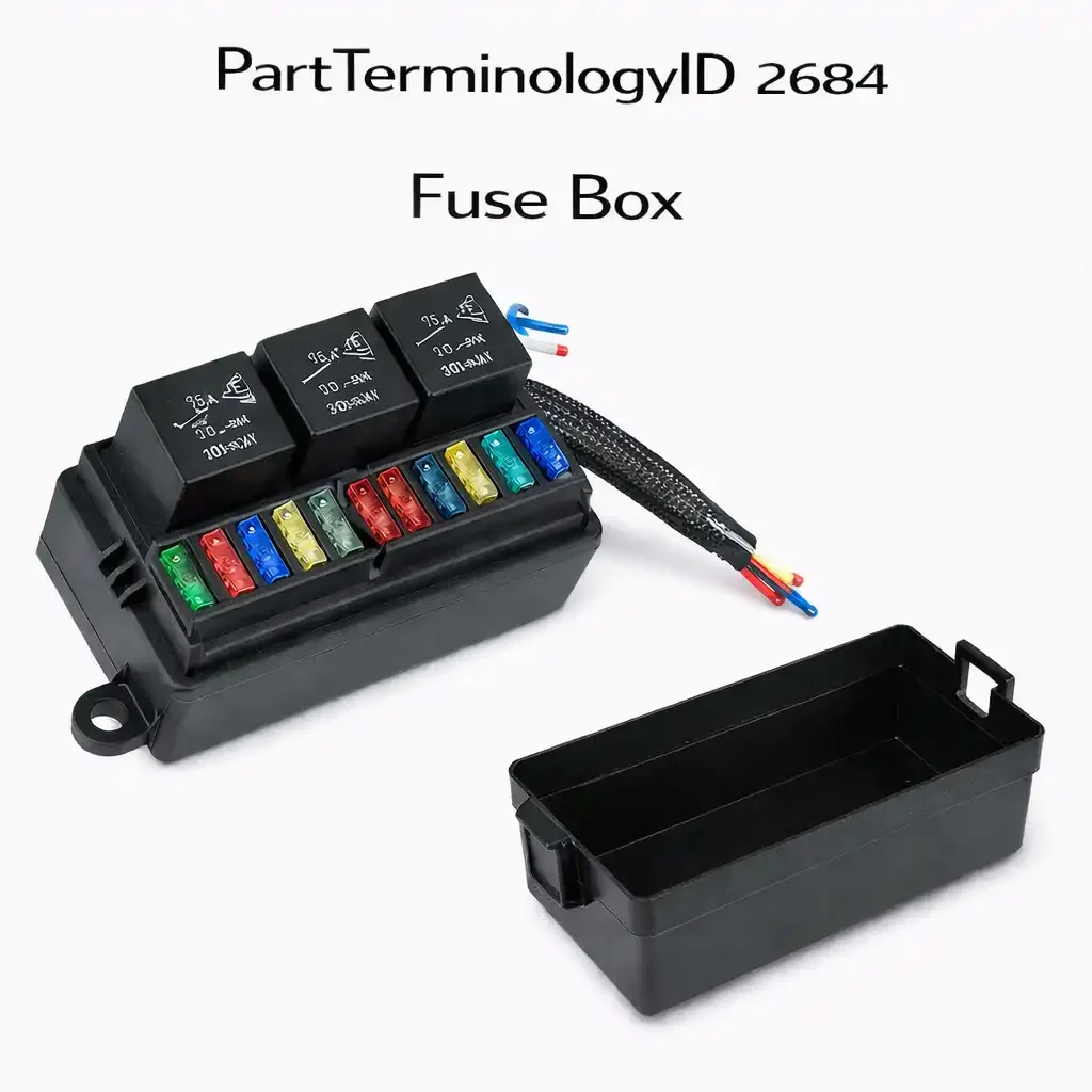
PartTerminologyID 2684, Fuse Box, is the complete electrical distribution center assembly that houses the fuse cavities, relay sockets, bus bars, enclosure body, cover, and mounting hardware that together distribute protected power from the vehicle's main electrical supply to the individual circuits throughout the vehicle. That definition covers the complete assembly correctly and leaves unresolved every question that determines whether the replacement fuse box includes the cover or requires it to be sourced separately, whether fuses and relays are included or must be transferred from the original, whether the fuse type layout across all positions matches the original so transferred fuses fit their intended cavities, whether the relay position count and socket configuration match so all relay modules from the original can be reinstalled, whether the wiring harness connector orientation matches so the vehicle's harness plugs mate to the correct output terminal positions with the correct circuit-to-position assignments, whether the mounting bracket configuration matches the original vehicle mounting points, whether the enclosure is sealed for the mounting location's environmental exposure level, whether the bus bar rating is adequate for the vehicle's full electrical load profile, and whether the cover label position diagram matches the replacement box's actual fuse and relay position assignments.
It does not specify whether the assembly includes the cover, whether fuses and relays are included or empty, the fuse type accepted at each position, the relay socket count and configuration, the wiring harness connector orientation and pin count, the mounting bracket configuration and hardware dimensions, the enclosure sealing designation, the bus bar current rating, the circuit count across fuse and relay positions, the cover label position diagram accuracy, the mounting location, whether the assembly covers the underhood or interior fuse box on vehicles with two separate boxes, or the trim level and option package compatibility. A listing under PartTerminologyID 2684 that specifies only year, make, and model without assembly completeness, fuse type layout, and mounting location cannot be evaluated by a technician who is replacing a flood-damaged fuse box and needs to confirm the replacement covers the correct electrical center on the vehicle before committing to a complete fuse and relay transfer.
For sellers, PartTerminologyID 2684 is the highest-consequence listing in the electrical protection series because the fuse box is the central node through which every protected circuit in the vehicle passes. A misspecified fuse box replacement does not merely fail to protect one circuit. It fails to protect every circuit simultaneously, or connects every circuit to the wrong fuse rating if the harness connector orientation is wrong, or leaves every relay-controlled circuit non-functional if the relay socket configuration does not match. The scale of the failure is proportional to the centrality of the component, and every attribute omission in the listing is amplified across the full circuit count of the vehicle's electrical system.
The additional complexity specific to PartTerminologyID 2684, beyond what was covered for PartTerminologyID 2680, is the trim level and option package compatibility problem. The fuse box is not a single part per model year. Most vehicle platforms use two to six fuse box variants within the same model year, differentiated by engine type, transmission type, body style, regional market, and optional equipment packages. The underhood fuse box on a vehicle with a trailer towing package has additional relay positions and higher-current fuse positions for the trailer brake controller, the trailer lighting relay, and the weight distribution system that are absent on the non-tow-package box. The interior fuse box on a vehicle with a sunroof, heated seats, and rear entertainment system has additional fuse positions for those circuits that are absent on the base trim box. A catalog that covers a complete model year range with a single listing will systematically fail every buyer whose vehicle has an option package that the single listed variant does not accommodate.
What the Fuse Box Does
Serving as the vehicle's complete electrical distribution node
The fuse box consolidates the vehicle's entire overcurrent protection architecture into a single serviceable assembly. Every circuit that requires overcurrent protection routes through a fuse position in the fuse box. Every high-current load that requires relay switching routes through a relay socket in the fuse box. Every high-current supply that requires branch protection routes through a maxi fuse or circuit breaker position in the fuse box. The fuse box is the point in the electrical system where a single assembly replacement can restore full overcurrent protection to the entire vehicle after a catastrophic damage event, which is why the completeness and accuracy of the replacement specification matters more here than at any other component in the electrical protection hierarchy.
The fuse box also serves as the physical and electrical interface between the vehicle's main battery supply and every branch circuit harness connector that routes power to the loads throughout the vehicle. The main supply enters the fuse box through a heavy-gauge cable at the battery terminal stud. The branch circuit harnesses exit the fuse box through multiple connector positions on the enclosure body, each connector carrying the protected output for a group of related circuits. The connector orientation, pin count, and position layout for each harness connector must match the original exactly, because the harness connectors are assembled with the wires in positions that correspond to the original fuse box's output terminal assignments. If the replacement box's output terminal positions differ from the original, the harness connectors will deliver each circuit's wire to the wrong terminal, mismatching every circuit to an incorrect fuse rating.
The cover label and position assignment verification function
The fuse box cover serves two functions: it physically protects the fuse and relay positions from moisture, road contamination, and contact with objects that could bridge adjacent fuse terminals, and it provides the position diagram that identifies which circuit or component each fuse and relay position serves. The cover label is the technician's primary reference for fuse and relay position assignments during service and is the driver's reference for locating a specific circuit's fuse during a non-start or circuit-failure event.
A replacement fuse box whose cover label does not match the position assignments of the replacement box's actual internal layout is a diagnostic hazard. The technician who transfers fuses from the original box to the replacement using the replacement box's cover label as a guide will install each fuse and relay at the position the label identifies, which is the correct position for a correctly matched replacement. But if the replacement box is a different variant with different position assignments, the cover label will direct the technician to install each fuse at a position that is incorrect for that circuit in this specific box variant. The resulting mismatch will place some circuits under incorrect fuse protection and may place safety-critical circuits such as the ABS pump and the airbag system under fuse ratings that are either too low, causing nuisance blowing at those positions, or too high, removing the overcurrent protection from those circuits entirely.
Relay integration and the switching function for high-current loads
Most fuse boxes integrate relay socket positions for the vehicle's high-current switched loads. The relay positions are fed from the same bus bar as the fuse positions but are switched by low-current control signals from the ECM, BCM, or other control modules rather than being always-active like the fuse-protected circuits. Common relay-controlled circuits in a typical underhood fuse box include the main cooling fan, the condenser fan, the fuel pump, the starter motor enable, the ABS pump motor, and the main power relay that enables the ignition circuit.
The relay socket configuration must match the relay module type installed at each position. The most common automotive relay is the ISO 280 mini relay with a five-pin blade configuration. Some positions use the larger ISO 280 maxi relay for higher-current loads. Some positions use purpose-specific relay modules with non-standard blade configurations. A replacement fuse box that uses standard ISO 280 mini relay sockets at positions where the original used maxi relay sockets will not accept the maxi relay module, leaving the corresponding high-current load without relay control. The relay socket type at each relay position must be stated individually in the listing, not summarized as a single relay type for all positions.
Underhood versus interior fuse box and the sealing requirement difference
Vehicles with two fuse boxes use the underhood box for high-current engine and chassis circuit protection and the interior box for lower-current body, comfort, and convenience circuit protection. The two boxes have fundamentally different environmental exposure profiles that drive different sealing requirements, different bus bar ratings, and often different fuse type layouts.
The underhood fuse box is exposed to engine heat, road spray, road salt, and underhood moisture from rain and engine cooling system steam during cold weather cold starts. It must be sealed against moisture ingress at all harness connector interfaces, wire entry points, and the cover-to-body mating surface. Its bus bar and cavity materials must withstand continuous operating temperatures up to 120 degrees Celsius in the underhood environment. Its cover must latch securely against the body with enough force to maintain the weather seal under underhood vibration. An interior replacement fuse box installed in an underhood position will fail from moisture ingress and heat degradation within one or two seasons. The mounting location, underhood or interior, must be stated as a mandatory required attribute for every listing under PartTerminologyID 2684 without exception.
The fuses-and-relays-included question and the transfer protocol
Whether a replacement fuse box includes fuses and relays is a critical assembly completeness attribute that determines what the buyer must do after receiving the part before the vehicle can operate. A bare housing replacement requires the buyer to transfer all fuses and relays from the original box to the replacement before installation. This transfer step is where most post-installation circuit errors originate: a fuse placed in the wrong position during transfer, a relay inserted backward, or a fuse from a previously incorrect installation in the original box transferred to the same incorrect position in the new box.
Listings that do not state whether fuses and relays are included will generate calls from buyers who receive a bare housing and assumed fuses were included, and will generate returns from buyers who receive a fuse-included assembly and assumed they would be doing their own transfer. Neither outcome is acceptable for a component that is the central protection node for the entire vehicle's electrical system. Fuse and relay inclusion must be stated unambiguously in the listing title or the first line of the listing description, not buried in a technical specifications table where the buyer may not read before ordering.
Why This Part Generates Returns
Buyers return fuse boxes because the assembly covers the wrong trim level variant and the relay positions for the trailer towing package are absent on a vehicle equipped with that package, the cover is not included and the buyer expected a complete assembly at the listed price, fuses and relays are not included and the buyer assumed they were, the fuse type layout does not match the original and mini blade fuses from the original cannot be installed in the ATO cavities of the replacement, the wiring harness connector orientation is mirrored relative to the original and the harness connectors from the vehicle plug into the box but with all circuits assigned to wrong positions, the mounting bracket configuration does not match the original vehicle mounting points and the box cannot be secured without modification, the bus bar rating is insufficient for the underhood box's simultaneous engine-on load and the bus bar overheats during the first extended drive, the enclosure is unsealed and the underhood installation produces moisture ingress at the harness connector interfaces within the first wet season, the cover label does not match the replacement box's position assignments and the technician installs fuses in the wrong positions based on the label, and the replacement covers the interior fuse box on a vehicle where the original was the underhood box due to listing ambiguity about the mounting location.
Status in New Databases
PIES/PCdb: PartTerminologyID 2684, Fuse Box
PIES 8.0 / PCdb 2.0: No change in PartTerminologyID or terminology label. Internal systems keyed to 2684 do not require remapping at the PIES 8.0 transition.
Top Return Scenarios
Scenario 1: "Wrong trim variant, trailer towing relay positions absent on tow-package vehicle"
The vehicle is equipped with the factory trailer towing package. The original underhood fuse box has 24 fuse positions and 8 relay positions including a trailer brake controller relay, a trailer lighting relay, and a trailer power relay. The replacement listing covers the vehicle year, make, and model but does not specify the trim variant or option package compatibility. The delivered replacement has 22 fuse positions and 6 relay positions, matching the non-tow-package configuration. Three relay modules from the original box have no corresponding sockets in the replacement. The trailer brake controller, trailer lighting circuit, and trailer power circuit are all non-functional after installation.
Prevention language: "Trim and option package compatibility: [base trim / tow package / sunroof package / list all variants covered]. This fuse box is compatible with [specific trim and option configuration]. Verify the variant matches the vehicle's installed option configuration before ordering. Vehicles with the factory trailer towing package require a fuse box with additional relay positions for the trailer brake controller, trailer lighting, and trailer power circuits that are absent on non-tow-package variants."
Scenario 2: "Cover not included, buyer expected complete assembly, vehicle exposed after installation"
The listing title states "Fuse Box" and the price reflects a bare housing without a cover. The buyer interprets "fuse box" as the complete assembly including the cover. The delivered part is the housing only. The vehicle's original cover was cracked in the same incident that damaged the housing. The buyer installs the bare housing with no cover, leaving all fuse and relay positions exposed to underhood moisture and road spray. The buyer returns the housing upon realizing the cover must be ordered separately at additional cost and additional lead time.
Prevention language: "Assembly includes: [housing only / housing and cover / housing, cover, and fuse assortment]. Cover: [included / not included, sold separately as part number X]. Fuses: [included / not included]. Relays: [included / not included]. Verify the assembly contents before ordering. Installing a bare fuse box housing without a cover in an underhood position will expose all fuse and relay positions to moisture and contaminants."
Scenario 3: "Harness connector orientation mirrored, all circuits at wrong fuse positions after installation"
The replacement fuse box has a mirrored harness connector orientation compared to the original. The main output harness connector is a 24-pin connector that physically mates with the vehicle harness connector because the connector body geometry is identical. However, the pin numbering within the connector is mirrored left-to-right from the original. Pin 1 in the original box connected circuit A to a 15-ampere fuse. Pin 1 in the replacement connects to the position that originally served circuit X with a 30-ampere fuse. All 24 circuits in the connector are connected to the wrong fuse positions. Several high-draw circuits immediately blow undersized fuses at their new positions. Several low-draw circuits are now unprotected at oversized positions. The technician traces the systematic mismatch to the mirrored connector and returns the box.
Prevention language: "Harness connector orientation: [matches OEM pin assignments as verified against OEM part number X]. The output harness connector pin assignments in this replacement box have been verified to match the original OEM configuration. If this part is being used as an alternative to OEM part number X, verify pin assignments independently before installation. A mirrored or rotated connector orientation will systematically assign all circuits in the connector to incorrect fuse positions."
Scenario 4: "Interior box delivered for underhood application, heat and moisture damage within two weeks"
The listing covers the vehicle year, make, and model without specifying mounting location. The buyer needs to replace the underhood fuse box. The delivered replacement is the interior variant, which is unsealed and rated for the lower temperature range of the interior environment. The buyer installs the interior box in the underhood position. Within two weeks of summer driving, the lower-rated plastic enclosure body shows heat warping near the engine block exhaust heat source, and moisture from a morning rain event has entered through the unsealed harness connector interfaces. Three cavities show corrosion deposits on the contact springs.
Prevention language: "Mounting location: [underhood / interior]. This fuse box is designed for [underhood / interior] installation. Underhood fuse boxes are sealed against moisture ingress and rated for sustained operating temperatures up to 120 degrees Celsius. Interior fuse boxes are unsealed and rated for the lower temperature range of the passenger compartment environment. Do not install an interior-rated fuse box in an underhood position."
Scenario 5: "Cover label position assignments do not match replacement box, fuses installed at wrong positions"
The replacement fuse box is a later production variant with a revised internal position layout compared to the early production original it is sold to replace. The cover included with the replacement has been updated for the new layout, but the listing images show the original cover label because the product photography was not updated when the internal layout changed. The technician uses the listing images as a reference for fuse installation. The technician installs fuses based on the old layout shown in the images. The actual replacement box has the ABS pump fuse and the fuel pump fuse in swapped positions compared to the old layout. The ABS pump, rated for a 30-ampere fuse, receives a 20-ampere fuse from the technician's transfer. The ABS pump fuse blows on the first ABS activation event.
Prevention language: "Cover label: [matches internal position layout of this replacement box / verify cover label against position layout before fuse installation]. Always verify the cover label position assignments against the actual internal layout of the replacement box before transferring fuses. Do not use the original box's cover label or listing images to guide fuse installation in a replacement box without confirming the position layout is identical."
Scenario 6: "Relay socket type mismatch at cooling fan position, maxi relay will not seat in mini socket"
The original fuse box has an ISO 280 maxi relay socket at the main cooling fan position to accommodate the high-current main fan relay. The replacement uses an ISO 280 mini relay socket at the same position. The listing states only "8 relay positions" without specifying socket type per position. The main cooling fan relay module is a maxi relay with larger blade dimensions that will not insert into the mini socket. The cooling fan relay cannot be installed. The cooling fan will not operate under any condition, including during AC compressor operation. The vehicle overheats during the first warm drive after installation.
Prevention language: "Relay socket type by position: [position 1: ISO 280 mini / position 2: ISO 280 mini / position 3: ISO 280 maxi / list all]. Verify the relay socket type at each position matches the relay module type from the original box. ISO 280 mini and maxi relay sockets are not interchangeable. A maxi relay module will not seat in a mini socket regardless of pin count match."
Scenario 7: "Fuses not included, buyer assumed transfer from original, original box is flood-damaged and fuses are corroded"
The buyer's original fuse box was damaged in a flood. The buyer orders a replacement fuse box assuming the transfer of fuses from the original is standard procedure. The delivered box is an empty housing. The original box's fuses are corroded from flood water exposure and cannot be reliably transferred because the fuse blade surfaces have corrosion deposits that will produce elevated contact resistance in the new box's clean contact springs. The buyer is left with an empty replacement box and 26 corroded fuses that should not be reused. The buyer returns the box to order a fuses-included variant at a higher price point that was not visible in the original search results.
Prevention language: "Fuses included: [yes, complete assortment at OEM-specified ratings per position / no, housing only]. For flood damage replacement applications where the original fuses are corroded, specify a fuse-included assembly or source a replacement fuse assortment covering all required ampere ratings for the fuse box before installation. Transferring corroded fuses to a new box introduces elevated contact resistance at those positions from the first installation."
Scenario 8: "Mounting bracket configuration differs, three of four mounting points do not align, box vibrates loose"
The replacement fuse box has a slightly different mounting bracket configuration from the original, with the fourth mounting point located 8mm from its original position. Three of the four mounting bolts align correctly and are installed. The fourth bolt hole does not align with the vehicle's mounting stud, so the fourth mounting point is left unbolted. The underhood fuse box is secured at three of four points. Engine vibration transmitted through the three mounting points fatigues the unsupported fourth corner and produces a rocking motion in the box. After 3,000 miles, the repeated flex stress cracks the enclosure body at the unsupported corner and the crack propagates to the nearest harness connector position, breaking the strain relief that secures that connector to the box body.
Prevention language: "Mounting configuration: [number of mounting points / mounting hole center-to-center spacing in mm / stud diameter in mm]. All mounting points must be used. Do not install this fuse box with any mounting point unsecured. An underhood fuse box secured at fewer than its designed mounting point count will experience vibration-induced flex stress that will fatigue the enclosure body and may crack the enclosure at harness connector positions."
What to Include in the Listing
Core essentials
PartTerminologyID: 2684
component: Fuse Box
mounting location: underhood or interior (mandatory, in title)
assembly contents: housing only, housing and cover, or housing cover and fuses (mandatory, in title or first line)
fuses included: yes with ampere rating assortment or no (mandatory)
relays included: yes or no (mandatory)
fuse type per position: ATO, mini blade, maxi blade, or mixed with position-level breakdown (mandatory)
total fuse position count (mandatory)
relay socket count and socket type per position: ISO 280 mini, ISO 280 maxi, or purpose-specific (mandatory)
circuit breaker position count where present (mandatory)
bus bar current rating in amperes (mandatory)
main supply terminal stud diameter in mm (mandatory)
harness connector count, pin count per connector, and orientation verified against OEM (mandatory)
mounting bracket configuration: mounting point count, center-to-center spacing, stud diameter (mandatory)
enclosure sealing: unsealed, sealed, or IP rating (mandatory)
operating temperature range in degrees Celsius (mandatory)
cover label matches internal position layout: yes or no (mandatory)
trim and option package compatibility (mandatory)
body dimensions: length, width, height in mm (mandatory)
OEM part number cross-reference (mandatory)
quantity: 1
Fitment essentials
year/make/model/submodel
engine type where fuse box variant differs by engine
transmission type where variant differs
option package compatibility: tow package, sunroof, heated seats, rear entertainment, regional market
note for vehicles with two fuse boxes distinguishing underhood from interior
note for mid-production-year layout revisions where early and late production vehicles use different position assignments within the same model year
OEM part number cross-reference for all variants covered
Image essentials
box shown from top with all fuse and relay positions labeled by position number and accepted type
harness connector positions shown with pin count and connector designations labeled
cover shown separately with position diagram visible and legible
main supply terminal stud shown with diameter labeled
mounting bracket configuration shown with center-to-center dimensions
sealing features shown on underhood variants including harness connector gaskets and cover seal
OEM part number label shown on box body
assembly contents shown with all included components laid out if fuses or relays are included
Catalog Checklist for ACES/PIES Teams
PartTerminologyID = 2684
require mounting location: underhood or interior (mandatory, first attribute)
require assembly contents statement: housing only, housing and cover, or housing cover and fuses (mandatory)
require fuse and relay inclusion status (mandatory)
require fuse type per position with position-level breakdown for mixed-type boxes (mandatory)
require total fuse position count (mandatory)
require relay socket count and socket type per position (mandatory)
require bus bar current rating (mandatory)
require harness connector orientation verified against OEM (mandatory)
require mounting bracket configuration (mandatory)
require sealing designation (mandatory)
require trim and option package compatibility (mandatory)
require cover label position assignment verification status (mandatory)
prevent mounting location ambiguity: a listing that does not state underhood or interior will be ordered for both positions; location must be the first attribute stated
prevent assembly contents ambiguity: cover, fuses, and relay inclusion must be stated unambiguously in the title or first line of description
prevent trim variant generalization: a single listing covering a full model year range without trim and option package differentiation will systematically fail tow-package, sunroof, and premium-trim buyers; variants must be differentiated
prevent cover label mismatch: cover label must be verified to match internal position layout of the specific replacement variant; mismatched labels produce systematic fuse installation errors
prevent relay socket type generalization: relay socket type must be stated per position; a summary relay count without socket type per position will generate cooling fan and fuel pump non-function returns
flag harness connector orientation as a mandatory verification attribute: a mirrored connector applies incorrect fuse ratings to all circuits in the connector simultaneously
flag mid-production-year layout revisions: catalog teams building year ranges must check for position layout changes within a model year that affect fuse and relay position assignments
differentiate from fuse block (PartTerminologyID 2680): the fuse block is the internal substrate; the fuse box is the complete assembly; when the complete assembly including enclosure and cover is being replaced, PartTerminologyID 2684 is correct
differentiate from multi-purpose fuse (PartTerminologyID 2676): the fuse box is the housing; the fuse is the replaceable element that occupies one position of the box
FAQ (Buyer Language)
What is the difference between a fuse box and a fuse block?
A fuse box is the complete assembly that includes the fuse block, enclosure body, cover, mounting brackets, and all integrated relay positions that together form the vehicle's electrical distribution center. A fuse block is the internal functional substrate containing the fuse cavities and bus bars, which may be a serviceable subassembly within the fuse box. When replacing the complete electrical center including its enclosure and cover, PartTerminologyID 2684 is the correct designation.
Does a replacement fuse box come with fuses and relays pre-installed?
Most replacement fuse boxes are sold as empty housings without fuses or relays. The fuses and relays from the original box are transferred to the replacement after verifying each fuse's ampere rating. Some assemblies include a fuse assortment kit. A small number of OEM-equivalent replacements include fuses and relays pre-installed. The listing must state explicitly whether fuses and relays are included, because a buyer who installs an empty housing without transferring fuses has no circuit protection at any position in the vehicle.
Why would a fuse box need to be replaced rather than just individual fuses?
A fuse box requires full replacement when a sustained fault current has overheated and deformed the cavity geometry or melted the bus bar, when flood or fire damage has compromised the enclosure and bus bar beyond individual repair, when physical impact has cracked the enclosure body or broken the mounting brackets, or when severe corrosion from long-term moisture exposure has elevated contact resistance at most cavities to the point where complete assembly replacement is more economical than attempting cavity-by-cavity repair.
Can I use a fuse box from a different trim level of the same vehicle?
With significant risk. Fuse boxes vary by trim level because different trim levels have different electrical options. A base-trim fuse box lacks relay positions for circuits standard on higher trims such as the sunroof, trailer towing, and heated seat circuits. Installing a lower-trim box on a higher-trim vehicle leaves those circuits without fuse protection or relay control. Always match the fuse box to the specific trim level and installed option configuration of the vehicle.
What does it mean when the fuse box cover label does not match the replacement?
The cover label identifies which circuit each position serves. If the replacement box's cover label does not match its actual internal position layout, installing fuses based on the label will place fuses at the wrong positions. Safety-critical circuits such as the ABS pump and fuel pump may receive incorrect fuse ratings. Always verify the cover label against the replacement box's actual position assignments before transferring any fuses.
My vehicle has two fuse boxes. Which PartTerminologyID covers each?
Both are covered by PartTerminologyID 2684. The listing must specify underhood or interior as a required attribute. The underhood box handles high-current engine and chassis circuits and requires sealed construction. The interior box handles lower-current body and convenience circuits and may be unsealed. A listing without a mounting location designation will be ordered for both positions and will fit neither correctly if the two boxes differ in size, sealing, and circuit count.
What happens if I install a fuse box with the wrong harness connector orientation?
A mirrored connector orientation will physically mate with the vehicle harness connector but will connect every circuit to the wrong fuse position. High-draw circuits will blow undersized fuses immediately. Low-draw circuits will operate without adequate protection at oversized fuse ratings. The systematic mismatch affects every circuit in the affected connector simultaneously, not just one. Always verify the harness connector pin assignments against the OEM specification before installation.
Cross-Sell Logic
Multi-Purpose Fuse (PartTerminologyID 2676): the overcurrent elements that occupy each fuse position; for flood damage or fire damage replacements where the original fuses are compromised, a complete fuse assortment covering all required ampere ratings must be sourced along with the replacement box
Fuse Block (PartTerminologyID 2680): the internal substrate of the fuse box; on vehicles where the fuse block is a serviceable subassembly, replacing only the block may be viable if the enclosure body and cover are undamaged
Fusible Link (PartTerminologyID 2692): the main supply protection upstream of the fuse box; if the fuse box failed from a sustained fault that also stressed the main supply circuit, the fusible link must be inspected and replaced before the new fuse box is energized
Relay: the switching modules that occupy the relay socket positions; relay modules should be inspected for heat damage or contact welding when the fuse box is replaced after an overcurrent fault event; a relay whose contacts are welded closed will activate its controlled load continuously after the new box is installed
Wiring Harness Repair Kit: for flood or fire damage where the harness connectors that plug into the fuse box have been damaged along with the box; replacing the fuse box without repairing the harness connectors will produce high-resistance connections at the output terminals of the new box from the first installation
Frame as "the fuse box is the central node where the battery supply is distributed to every protected circuit in the vehicle. The fuses protect each circuit from fault current. The relays switch the high-current loads the box supplies. The fusible link protects the supply feeding the box. The harness connectors route the protected outputs to the loads. All are in the same electrical distribution pathway from the battery terminal to every load in the vehicle."
Final Take for PartTerminologyID 2684
Fuse Box (PartTerminologyID 2684) is the PartTerminologyID in the electrical protection series with the broadest failure consequence of any single listing error in the category. A misspecified fuse block affects the circuits in one block. A misspecified fuse box affects every circuit in the vehicle simultaneously because every circuit routes through the fuse box. The harness connector orientation error does not affect one circuit. It systematically misprotects every circuit in every affected connector simultaneously. The trim variant error does not leave one circuit unprotected. It leaves every option-package circuit in the vehicle without a relay socket or fuse position. Every attribute omission in a fuse box listing is multiplied by the circuit count of the vehicle's electrical system.
State the mounting location in the title. State the assembly contents in the first line. State fuse and relay inclusion. State the fuse type layout per position. State the relay socket type per position. State the bus bar rating. State the harness connector orientation verification. State the trim and option package compatibility. State the cover label verification status. State the sealing designation. State the mounting configuration. For PartTerminologyID 2684, mounting location, assembly completeness, and trim compatibility are the three attributes that determine whether the replacement fuse box restores full electrical protection to the entire vehicle or generates a return that requires a complete fuse and relay re-transfer after the buyer discovers the mismatch at the installation stage.