Fuse Block (PartTerminologyID 2680): Where Fuse Type Compatibility, Circuit Count, and Mounting Configuration Determine Whether Every Circuit Has a Protected Home
Written by Arthur Simitian | PartsAdvisory
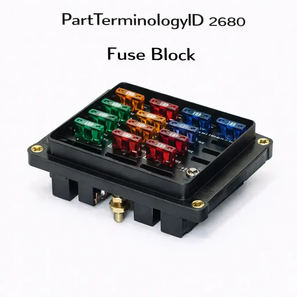
PartTerminologyID 2680, Fuse Block, is the housing assembly that contains the fuse cavities, bus bars, and circuit output terminals that distribute protected electrical power from the vehicle's main supply to individual circuits through individual overcurrent protection elements. That definition covers the function correctly and leaves unresolved every question that determines whether the replacement fuse block accepts the same fuse type as the original cavities, whether the circuit count matches the number of protected circuits in the vehicle's wiring harness that connect to the block, whether the mounting configuration aligns with the original mounting hardware positions in the vehicle's engine bay or interior, whether the bus bar current rating is adequate for the total simultaneous current draw of all circuits served by the block, whether the main supply terminal type and stud size match the vehicle's battery feed cable termination, whether the circuit output terminals accept the wire gauge and terminal type of the vehicle's existing harness connectors, whether the block includes relay positions and in what count and configuration, and whether the block is designed for the same environmental exposure level as the original in terms of moisture sealing and operating temperature range.
It does not specify the fuse type each cavity accepts, whether it is ATO standard blade, mini blade, maxi blade, or a mixed configuration, the total circuit count, the relay position count where relays are integrated, the bus bar current rating in amperes, the main supply terminal type and stud diameter, the circuit output terminal type and wire range, the mounting hole pattern and hardware dimensions, whether the block is sealed against moisture ingress, the operating temperature range, the body material, or whether the block is a standalone component or requires a specific enclosure cover to form a complete fuse box assembly. A listing under PartTerminologyID 2680 that specifies only year, make, and model without fuse type, circuit count, and bus bar rating cannot be evaluated by a technician replacing a heat-damaged fuse block on a vehicle that may have used multiple block variants across the production run depending on the trim level and optional equipment installed.
For sellers, PartTerminologyID 2680 sits at the intersection of two separate catalog populations: OEM replacement buyers who need an exact match to restore a damaged original block, and aftermarket addition buyers who are adding circuits to a vehicle that did not originally have a fuse block at the desired location. The OEM replacement buyer needs every dimension and circuit detail to match the original precisely. The aftermarket addition buyer needs to know the block's capacity, fuse type, bus bar rating, and mounting options to determine whether it serves the planned circuit additions adequately. A listing built only for one of these populations will generate returns or questions from the other. The circuit count, bus bar rating, and mounting configuration must be stated clearly enough to serve both buyer types without requiring a support inquiry before purchase.
The additional complexity specific to PartTerminologyID 2680 is the fuse type mixing problem. Many vehicles use fuse blocks that mix fuse types across positions: standard ATO positions for high-current circuits, mini blade positions for low-current electronic circuits, and maxi blade positions for the highest-current loads such as the cooling fan, the HVAC blower, and the ABS motor. A replacement fuse block that covers the correct circuit count but accepts only ATO standard blade fuses at all positions cannot accommodate the mini blade positions in the original block without requiring the technician to swap all mini blade fuses for ATO fuses at different ampere ratings, which changes the circuit protection configuration away from the vehicle manufacturer's design. The fuse type layout across all positions must be stated explicitly, not summarized as a single fuse type designation for the block as a whole.
What the Fuse Block Does
Distributing protected power to individual circuits
The fuse block's central function is to take battery positive voltage from one or a small number of main supply terminals and distribute it to a larger number of individual circuit output terminals, with a fuse cavity between the bus bar and each output terminal that limits the current any individual circuit can draw before the fuse interrupts that circuit's supply. This distribution function means the fuse block is simultaneously the current source for every circuit it serves and the protection boundary that prevents any one circuit's fault from drawing enough current to damage the bus bar, the supply wiring, or the other circuits sharing the same bus bar supply.
The bus bar's current rating determines the maximum simultaneous load the block can distribute without overheating. A bus bar rated at 100 amperes can distribute up to 100 amperes across all active circuits simultaneously. If the vehicle's circuits that connect to this block could all draw simultaneously at their maximum fuse ratings, the sum of all fuse ratings in the block may well exceed 100 amperes. The bus bar rating is not the sum of all fuse ratings but the maximum realistic simultaneous draw based on the actual operating profiles of the circuits the block serves. However, in unusual conditions such as a vehicle fire where electrical loads are uncontrolled, or in a vehicle with extensive aftermarket electrical additions that all activate simultaneously, the simultaneous draw can approach or exceed the bus bar rating. The bus bar rating must be stated so buyers adding circuits to an existing block can determine whether the block has adequate remaining capacity for the planned additions.
Maintaining contact integrity at each fuse cavity
The fuse block's contact springs at each cavity must maintain sufficient clamping force on the fuse blade to produce a contact resistance below the threshold that generates significant heat during normal circuit operation. The contact resistance specification for a properly functioning fuse block cavity is typically below 5 milliohms. At this resistance, a 15-ampere circuit produces less than 1 milliwatt of heat at the contact interface, which is negligible in the context of the circuit's total thermal load. As contact resistance increases from spring fatigue, corrosion, or mechanical deformation, the heat generated at the contact interface rises with the square of the current, and at 50 milliohms a 15-ampere circuit generates enough heat to eventually discolor the fuse body and soften the plastic around the cavity opening.
A replacement fuse block must have new contact springs with full temper and the correct spring force geometry for the fuse type it accepts. A fuse block sourced from a low-cost supplier with underspecified contact spring material will produce adequate contact force initially but will relax under the first few dozen thermal cycles, reaching a contact resistance above the thermal threshold within one to two years of service. The contact spring material specification and the spring force value at the designed insertion depth are not attributes commonly stated in catalog listings but are the mechanical characteristics that determine whether the replacement fuse block provides the same service life as the original.
Accommodating relay positions and integrated protection functions
Many fuse blocks include relay socket positions integrated into the same housing, sharing the bus bar supply with the fuse cavities. The relay positions accept plug-in relay modules that switch high-current loads such as the main cooling fan, the fuel pump, the headlights, and the horn under control of low-current electronic signals. On vehicles where the fuse block and relay block are combined into a single housing, the replacement block must include the same relay position count, relay socket type, and relay socket configuration as the original, or the vehicle's relay-controlled circuits will have no relay socket to occupy after the block replacement.
Some fuse blocks also include integrated circuit breakers at specific positions for loads that experience frequent overloads in normal operation, such as power window motors and power seat motors. A circuit breaker position resets automatically after the overload condition clears, unlike a fuse position that requires manual fuse replacement after every overload event. A replacement block that uses a fuse cavity at a position where the original used a circuit breaker cavity will require the technician to manually replace the fuse every time the power window motor stalls at its travel limit, which is a normal operating event that the original circuit breaker design accommodated automatically. The position-level distinction between fuse, relay, and circuit breaker positions must be stated in the listing for every position in the block.
Sealing requirements for underhood and exposed mounting locations
Fuse blocks mounted in the engine bay, near the battery, or under the vehicle are exposed to moisture, road salt, and temperature extremes that interior-mounted fuse blocks do not experience. An underhood fuse block must have sealed wire entry points, a sealed main supply terminal, and a body material that resists the thermal cycling between winter cold start and summer operating temperatures without cracking or warping. An unsealed replacement fuse block installed in an underhood location on a vehicle operated in a road salt environment will accumulate salt solution on the bus bar and contact springs within one winter season, producing corrosion that elevates contact resistance at every cavity in the block.
The sealing designation of the replacement block must match the original's environmental rating for the installation location. An IP rating, if stated, provides a standardized measure of the block's ingress protection against water and particulates. A block without an IP rating or a sealing designation should not be specified for underhood or other exposed mounting locations regardless of its fuse type and circuit count match to the original.
Why This Part Generates Returns
Buyers return fuse blocks because the fuse type accepted by the replacement cavities does not match the original and mini blade fuses from the original block cannot be used in the ATO cavities of the replacement, the circuit count is lower than the original and one or more harness connectors have no corresponding output terminal position in the replacement block, the bus bar rating is below the total simultaneous load of all circuits served and the bus bar overheats within the first week of operation, the main supply terminal stud diameter does not match the vehicle's battery feed cable lug and the cable cannot be secured to the replacement block without a different terminal, the mounting hole pattern does not align with the original mounting hardware positions and the block cannot be secured in the original location without drilling new holes, the relay position count is lower than the original and one or more relay modules have no socket in the replacement, the block is unsealed and the installation location is an underhood environment that produces moisture ingress at the fuse cavities within one season, the circuit output terminal type does not accept the vehicle's existing harness connector and the harness connectors must be cut and re-terminated to connect to the replacement block, and the block is a standalone housing without the cover required to seal the assembly and the cover must be sourced separately at additional cost.
Status in New Databases
PIES/PCdb: PartTerminologyID 2680, Fuse Block
PIES 8.0 / PCdb 2.0: No change in PartTerminologyID or terminology label. Internal systems keyed to 2680 do not require remapping at the PIES 8.0 transition.
Top Return Scenarios
Scenario 1: "Replacement accepts ATO only, original has mixed ATO and mini blade positions, mini fuses do not fit"
The original fuse block has 20 positions: 14 standard ATO cavities and 6 mini blade cavities. The replacement block has 20 ATO cavities. The listing states "20 position fuse block" without specifying that all 20 positions are ATO standard. The technician installs the replacement and attempts to insert the 6 mini blade fuses from the original block. The mini blade fuses will not engage the ATO contact springs. Six circuits are left unprotected and unconnected.
Prevention language: "Fuse type by position: [list of positions with accepted fuse type per position]. This block accepts [ATO standard blade / mini blade / maxi blade / mixed as specified per position]. Verify that the fuse type accepted at each position matches the fuse types installed in the original block. A block that accepts ATO standard blade fuses cannot accommodate mini blade fuses from the original installation without replacing all mini blade fuses with ATO-type fuses at ampere ratings appropriate for each circuit."
Scenario 2: "Circuit count two fewer than original, two harness connectors unconnected after installation"
The original block has 18 output terminal positions. The replacement has 16. The vehicle's wiring harness has 18 individual circuit connectors that route to the fuse block. After installation of the 16-position replacement, two harness connectors have no corresponding terminal position. The two unconnected circuits are the rear window defogger and the heated seat. Both functions are non-operational after the block replacement.
Prevention language: "Circuit count: [X] fuse positions. This block provides [X] individual circuit output positions. Verify the circuit count matches or exceeds the number of circuits in the vehicle's harness that connect to the fuse block. Installing a block with fewer positions than the original will leave one or more vehicle circuits without a fuse block connection."
Scenario 3: "Bus bar overheats after installation, fuse block body discolors within first week"
The replacement fuse block has a bus bar rated at 80 amperes. The vehicle's simultaneous peak load across all circuits served by the block reaches 95 amperes during a cold morning with the rear defogger, heated seats, blower motor, headlights, and heated mirrors all active simultaneously. The 95-ampere simultaneous load exceeds the 80-ampere bus bar rating. Within the first week of winter operation, the fuse block body shows visible discoloration around the bus bar area and several fuse cavities exhibit elevated contact resistance from the heat degradation of the contact spring temper.
Prevention language: "Bus bar current rating: [X] amperes total. Verify the bus bar rating meets or exceeds the maximum simultaneous current draw of all circuits served by this block. On vehicles with multiple high-current accessories that may operate simultaneously in cold weather, calculate the worst-case simultaneous load before selecting a replacement block. A bus bar operated above its rated current will overheat and degrade the contact spring temper at all fuse cavities in the block."
Scenario 4: "Main supply stud diameter wrong, battery feed cable lug does not fit, installation abandoned"
The original block's main supply stud is M8 diameter. The replacement block's stud is M6. The vehicle's battery feed cable has a 10mm hole in its ring terminal lug, sized for the M8 stud. The M6 stud passes through the ring terminal but cannot be torqued to the cable's required clamping force without the ring terminal pulling off the stud under the torque load. The technician cannot complete the installation and returns the block.
Prevention language: "Main supply terminal: [stud type / stud diameter in mm / stud thread pitch]. This block uses an [M6 / M8 / M10] supply stud. Verify the main supply stud diameter matches the ring terminal hole diameter of the vehicle's battery feed cable before installation."
Scenario 5: "Relay positions absent, replacement is fuse-only block, relay modules have no sockets"
The original block has 16 fuse positions and 4 relay positions. The replacement is a fuse-only block with 16 fuse positions and no relay sockets. The listing does not state the relay position count. The technician installs the block and finds 4 relay modules from the original block have nowhere to mount. The cooling fan relay, the fuel pump relay, the horn relay, and the starter relay are all uninstalled. The vehicle will not start and the cooling fan and horn do not function.
Prevention language: "Relay positions: [X]. Fuse positions: [X]. This block includes [X] relay socket positions in addition to [X] fuse positions. Verify the relay position count and socket type match the original block before installation. A fuse-only replacement block installed on a vehicle whose original block included relay positions will leave all relay modules without mounting sockets."
Scenario 6: "Unsealed block in underhood location, salt corrosion at all cavities within one winter"
The original underhood fuse block has sealed wire entry grommets and a sealed main supply terminal. The replacement is an unsealed block of the correct fuse type and circuit count. After one northern winter, road salt solution has accumulated on the bus bar and all 18 cavity contact springs. Twelve of the 18 cavities show elevated contact resistance from contact surface oxidation. Three circuits are intermittent. The technician returns the block and notes the corrosion timeline began immediately after the first road salt exposure.
Prevention language: "Sealing: [unsealed / sealed with wire entry grommets / IP[X] rated]. This block is [unsealed / sealed for underhood use]. For underhood, near-battery, and other exposed mounting locations, a sealed fuse block with sealed wire entry points and a sealed main supply terminal is required. An unsealed block installed in a moisture and road salt environment will experience contact corrosion at all fuse cavities within one to two seasons."
What to Include in the Listing
Core essentials
PartTerminologyID: 2680
component: Fuse Block
fuse type accepted per position: ATO, mini blade, maxi blade, or mixed with position-level breakdown (mandatory, in title)
total fuse position count (mandatory)
relay position count and relay socket type (mandatory)
circuit breaker position count where present (mandatory)
bus bar current rating in amperes (mandatory)
main supply terminal type: stud, bolt, or ring terminal (mandatory)
main supply stud diameter in mm (mandatory)
circuit output terminal type and wire range in AWG (mandatory)
mounting hole pattern and hardware dimensions in mm (mandatory)
body material: nylon, polycarbonate, or glass-filled nylon (mandatory)
sealing designation: unsealed, sealed, or IP rating (mandatory)
operating temperature range in degrees Celsius (mandatory)
cover included or sold separately (mandatory)
body length, width, and height in mm (mandatory)
OEM part number cross-reference where available (mandatory)
quantity: 1
Fitment essentials
year/make/model/submodel
mounting location: underhood, interior, near-battery, or under-vehicle
note for vehicles where fuse block variant differs by trim level or optional equipment
note for aftermarket addition applications stating maximum remaining bus bar capacity after installed circuit loads
OEM part number cross-reference for technician verification against original block label
Image essentials
block shown from top with all fuse cavity positions labeled by accepted fuse type and position number
relay socket positions labeled and numbered
main supply terminal shown with stud diameter labeled
mounting hole pattern shown with center-to-center dimensions
body dimensions shown with length, width, and height measurement references
sealing features shown including wire entry grommets and supply terminal seal where present
OEM part number label shown on block body where present
Catalog Checklist for ACES/PIES Teams
PartTerminologyID = 2680
require fuse type per position with position-level breakdown for mixed-type blocks (mandatory)
require total fuse position count (mandatory)
require relay position count and socket type (mandatory)
require bus bar current rating (mandatory)
require main supply stud diameter (mandatory)
require circuit output terminal type and wire range (mandatory)
require mounting hole pattern dimensions (mandatory)
require sealing designation (mandatory)
require cover included or separate status (mandatory)
prevent fuse-type-only designation: stating only one fuse type for a mixed-type block will generate returns from buyers whose circuits require the other fuse type; position-level fuse type breakdown must be required
prevent circuit count understatement: a block with fewer positions than the original leaves circuits unconnected; circuit count must match or exceed the original
prevent bus bar rating omission: a block with an insufficient bus bar rating for the vehicle's simultaneous load profile will overheat and degrade all contact springs; bus bar rating must be required
prevent sealing omission: an unsealed block in an underhood application will corrode within one season in a road salt environment; sealing designation must be required for all listings and must be flagged for underhood applications
flag relay position count as mandatory: a fuse-only block installed on a vehicle that requires relay positions leaves all relay-controlled circuits non-functional
differentiate from fuse box (PartTerminologyID 2684): the fuse block is the internal functional substrate; the fuse box is the complete assembly including the enclosure; clarify in every listing whether the part is the block alone or the complete box assembly
differentiate from multi-purpose fuse (PartTerminologyID 2676): the fuse block is the housing; the fuse is the replaceable overcurrent element that occupies one position of the block
differentiate from fuse holder (PartTerminologyID 2688): the fuse holder is a single-circuit inline or panel-mounted device; the fuse block distributes power to multiple circuits from a common supply
FAQ (Buyer Language)
What is the difference between a fuse block and a fuse box?
A fuse block is the internal housing assembly that contains the fuse cavities, bus bars, and terminal connections for a set of protected circuits. A fuse box is the complete assembly including the fuse block, the enclosure cover, mounting brackets, and any integrated relay positions that together form the vehicle's fuse and relay center. On some vehicles the fuse block is a serviceable subassembly within the fuse box. On others the fuse block and fuse box are a single non-separable unit sold as one assembly. The listing must state which is being sold.
What does the bus bar current rating mean for a fuse block?
The bus bar is the common conductor that distributes battery positive voltage from the main supply terminal to all fuse cavities. The bus bar rating is the maximum total current the bus bar can carry continuously across all active circuits without overheating. If the sum of all simultaneously active circuit currents exceeds the bus bar rating, the bus bar will overheat and degrade the contact spring temper at all cavities. For vehicles with multiple high-current accessories that operate simultaneously in cold weather, calculate the worst-case simultaneous load before selecting a replacement block.
Can I use a fuse block designed for mini blade fuses with standard ATO blade fuses?
No. The cavity geometry and contact spring spacing in a mini blade fuse block are designed for the mini blade's narrower blade dimensions. A standard ATO blade fuse will not insert correctly into a mini blade cavity. Forcing it will deform the contact springs and damage the cavity permanently. The fuse type accepted at each cavity position must match the fuse type originally installed at that position.
How do I identify the correct replacement fuse block for my vehicle?
Count the fuse positions and note the fuse type each cavity accepts, including whether the block has mixed ATO and mini blade positions. Measure the mounting hole pattern and note the main supply terminal stud size. Count the relay socket positions. Record the OEM part number from the block's body label if present. The circuit count, fuse type layout, mounting configuration, and relay count together identify the correct replacement more reliably than year, make, and model alone on vehicles where block variants differ by trim level.
What causes fuse block contact springs to fail?
Contact springs fail from thermal fatigue caused by repeated heating and cooling cycles that gradually relax the spring temper, from corrosion caused by moisture intrusion that deposits oxidation on the contact surface, and from mechanical deformation caused by inserting incorrect fuse types or by forcing fuses with excessive insertion force. All three failure modes increase contact resistance at the affected cavities, which generates heat that accelerates the failure of adjacent cavities and eventually produces intermittent circuit operation at the high-resistance positions.
Cross-Sell Logic
Multi-Purpose Fuse (PartTerminologyID 2676): the overcurrent protection element that occupies each cavity of the fuse block; when replacing a fuse block, all fuses from the original block should be inspected and those showing heat discoloration or deformed blades should be replaced with new fuses at the correct ampere rating for each circuit position
Fuse Box (PartTerminologyID 2684): the complete enclosure assembly that houses the fuse block; if the fuse block is a serviceable subassembly, the fuse box cover and mounting hardware should be inspected for heat damage when the block is replaced due to an overcurrent event
Fusible Link (PartTerminologyID 2692): the main battery circuit protection upstream of the fuse block; if the fuse block failed from an overcurrent event that also blew the main fusible link, the fusible link must be replaced to restore power to the fuse block after the block replacement
Fuse Holder (PartTerminologyID 2688): a single-circuit inline fuse holder for added circuits that cannot be accommodated in the existing fuse block due to insufficient remaining positions
Relay: the switching modules that occupy the relay socket positions in a combined fuse and relay block; relay modules should be inspected for heat damage when the fuse block is replaced after a fault event that produced sustained overcurrent through the bus bar
Frame as "the fuse block distributes the power the battery supplies through the fusible link. The fuses in each cavity protect the circuits the block feeds. The fuse box enclosure protects the block from the environment. The relay modules in the integrated relay positions switch the high-current loads the block supplies. All are in the same overcurrent protection hierarchy from the battery terminal to the individual circuit load."
Final Take for PartTerminologyID 2680
Fuse Block (PartTerminologyID 2680) is the PartTerminologyID in the electrical protection housing series where mixed-fuse-type position layouts and circuit count mismatches together account for the highest rate of returns with incomplete-repair consequences. A block that accepts only ATO fuses when the original had six mini blade positions installs physically, occupies the original mounting location, and accepts the majority of the original fuses, but leaves six circuits unprotected and unconnected after the installation is complete. The technician discovers the problem only after the block is bolted down and the harness is reconnected. A block with two fewer positions than the original produces the same discovery-after-installation problem with two unconnected harness circuits. Both failures are entirely preventable by listing the fuse type accepted at every position and the total circuit count as required attributes before the part is sold.
State the fuse type layout per position in the listing. State the total circuit count. State the relay position count. State the bus bar current rating. State the main supply stud diameter. State the sealing designation. State the mounting hole pattern. State the cover status. State whether the block is a subassembly or a complete assembly. For PartTerminologyID 2680, fuse type layout, circuit count, and bus bar rating are the three attributes that determine whether the replacement fuse block restores complete overcurrent protection to every circuit in the vehicle or generates a return with unprotected circuits discovered after the installation is committed.