Hazard Warning Flasher (PartTerminologyID 2668): Where Flash Rate, Load Compatibility, and Terminal Configuration Determine Whether All Four Corners Flash in Compliance
Written by Arthur Simitian | PartsAdvisory
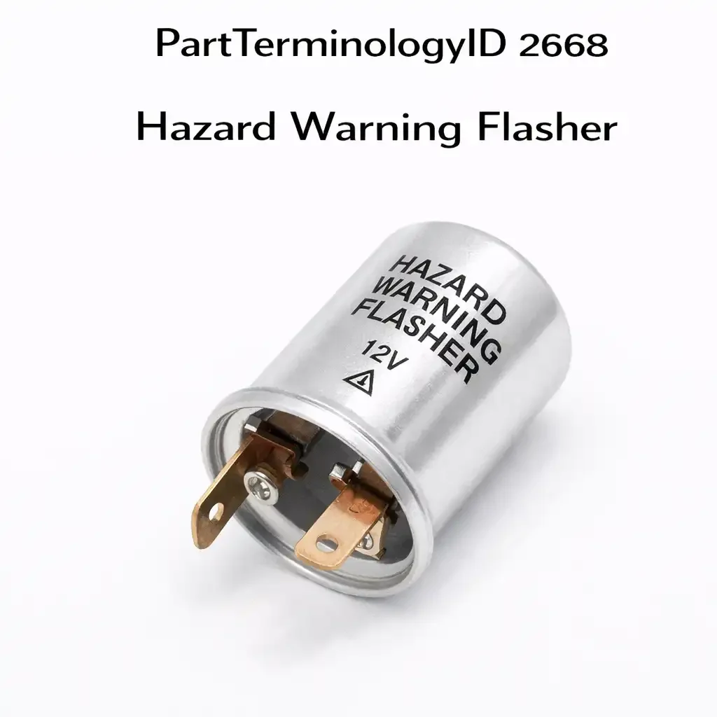
PartTerminologyID 2668, Hazard Warning Flasher, is the relay unit that interrupts the circuit to all four turn signal lamps simultaneously at a regulated rate when the driver activates the hazard warning switch, producing the synchronized four-corner flash pattern required by federal motor vehicle safety standards for stopped or disabled vehicle signaling. That definition covers the function correctly and leaves unresolved every question that determines whether the replacement flasher produces a flash rate within the federally mandated 60 to 120 flashes-per-minute range at the vehicle's actual lamp load, whether it can handle the combined current draw of all four turn signal lamps simultaneously without overheating or rate deviation, whether its terminal count and terminal designations match the flasher socket in the vehicle's fuse and relay panel or instrument panel mounting location, whether its physical body dimensions fit the mounting socket or bracket without modification, whether it serves the hazard function only or also serves the turn signal function as a combined unit, whether it is compatible with the vehicle's bulb type including incandescent or LED, and whether it includes a pilot lamp terminal for the hazard indicator lamp on the instrument cluster.
It does not specify the flash rate in flashes per minute at the rated load, the maximum lamp load in amperes the flasher can handle before the flash rate deviates from specification, the terminal count, the terminal designations and their circuit functions, whether the flasher uses a thermal bimetal element or an electronic timer circuit to generate the flash interval, whether it covers hazard only or combined hazard and turn signal functions, the physical body dimensions and the socket engagement type, the pilot lamp terminal current output, the operating voltage range, or whether the flasher is load-sensitive and will hyperflash with LED bulbs. A listing under PartTerminologyID 2668 that specifies only year, make, and model without terminal configuration, load rating, and flash rate cannot be evaluated by a technician replacing a flasher that produces an out-of-specification rate or no flash at all on a vehicle that may have used multiple flasher suppliers across the production run.
For sellers, PartTerminologyID 2668 presents a specific compliance dimension that most other electrical connector and switch PartTerminologyIDs do not. The hazard warning flasher is a federally regulated safety device. Federal Motor Vehicle Safety Standard 108 establishes the minimum and maximum flash rate for hazard warning systems, and a replacement flasher that produces a flash rate outside that range on the vehicle's actual lamp load is non-compliant for on-road use regardless of whether it physically fits the socket and illuminates the lamps. A listing that does not state the flash rate and the load range within which that rate is maintained gives the buyer no means to verify compliance before installation, and a buyer who installs a non-compliant flasher on a vehicle and subsequently has a hazard warning failure during a roadside emergency has a return claim that goes beyond a simple specification mismatch.
The additional complexity specific to PartTerminologyID 2668 is the combined-versus-separate flasher architecture. Vehicles produced before approximately 1996 typically used two separate flasher units: one for the hazard warning system and one for the turn signals, each installed in a different socket location in the fuse panel or under the dash. Vehicles produced from the mid-1990s onward increasingly used a single combined flasher unit that serves both the hazard warning and turn signal functions from a single socket. A catalog that covers a 1994 through 2002 model range with a single listing may span both the separate-flasher and combined-flasher architectures within the same year range. The listing must distinguish which architecture the flasher covers, because a hazard-only flasher installed in a combined socket will disable the turn signal function, and a combined flasher installed in a vehicle that expects a separate hazard unit may produce incorrect circuit behavior if the combined unit's turn signal output interferes with the vehicle's dedicated turn signal flasher circuit.
What the Hazard Warning Flasher Does
Interrupting the four-lamp circuit at a regulated rate
The hazard warning flasher's core function is to interrupt the current path to all four turn signal lamps at a rate that produces a visible, attention-commanding flash pattern. When the hazard switch is activated, battery positive voltage is applied to the flasher's input terminal. The flasher's internal switching element, either a bimetal thermal strip or an electronic timer circuit, opens and closes the output circuit at intervals that produce the specified flash rate. The output voltage is routed through the hazard switch contacts to all four turn signal lamp circuits simultaneously, turning all four lamps on and off in synchrony.
The flash rate the flasher produces is determined by two factors: the flasher's internal timing element and the current load connected to the output circuit. In a thermal bimetal flasher, the bimetal strip heats from the current flowing through it and bends to open the circuit, then cools and closes again. The rate of heating and cooling depends on the current magnitude, which is determined by the number and wattage of the connected lamps. A thermal flasher calibrated for a four-lamp incandescent load will produce the correct flash rate only when the connected load falls within its calibrated current range. Adding a fifth lamp, removing one lamp, or replacing incandescent bulbs with LEDs changes the current magnitude and shifts the flash rate outside the calibrated range.
An electronic timer flasher uses a capacitor-resistor timing circuit or an oscillator to generate the flash interval independently of the connected load current. The flash rate of an electronic timer flasher remains constant across a wide range of connected loads, making it compatible with LED bulbs, mixed incandescent and LED installations, and applications where one lamp may be temporarily absent due to a burned-out bulb. The listing must specify the flasher type so the buyer can determine whether the replacement will maintain the correct rate with the bulb configuration installed in the vehicle.
Handling the combined four-lamp current load
The hazard warning flasher carries a higher current load than the turn signal flasher because it activates all four turn signal lamps simultaneously rather than two lamps on one side. A standard front and rear incandescent turn signal lamp set uses 1157 or equivalent dual-filament bulbs with a turn signal filament drawing approximately 2 amperes each. With four lamps active simultaneously, the hazard flasher output circuit carries approximately 8 amperes at the peak of each flash cycle. On trucks and SUVs with additional side marker lights or with higher-wattage turn signal bulbs, the combined load may reach 12 to 15 amperes.
The flasher's current rating must exceed the vehicle's maximum combined lamp load with adequate thermal margin. A flasher rated for 8 amperes installed on a vehicle with a 12-ampere combined hazard load will operate within its rated range initially but will experience elevated component temperatures during sustained hazard operation, such as a long roadside stop with the hazard lights active. Sustained operation at or above the thermal limit causes the flasher's internal components to degrade, producing a flash rate that drifts outside specification over time before the unit fails entirely. The current rating must be stated and must be verified against the vehicle's combined hazard lamp load before the listing is built.
The pilot lamp terminal and the instrument cluster indicator
Most hazard warning flashers include a pilot lamp terminal, designated P or X on most units, that provides a low-current output to illuminate the hazard indicator lamp on the instrument cluster. The pilot lamp terminal output is a small fraction of the main lamp output current, typically 50 to 200 milliamperes, sufficient to illuminate the indicator lamp without the full switched load of the turn signal circuits. On vehicles that route the hazard indicator lamp through the pilot terminal, a flasher without a pilot terminal will leave the hazard indicator lamp dark during hazard operation. The buyer will install the flasher, confirm the four exterior lamps flash correctly, and return the unit when they notice the instrument cluster indicator does not illuminate.
On some vehicle applications the instrument cluster hazard indicator is powered directly from one of the four lamp circuits rather than from a dedicated pilot terminal. On these applications a flasher without a pilot terminal functions correctly because the indicator draws its power from the lamp circuit rather than from a separate pilot output. The listing must state whether the pilot terminal is present and must note which indicator circuit architecture the flasher is designed for, so the buyer can confirm the replacement matches the original before installation.
LED compatibility and the hyperflash problem
The LED compatibility issue is the single most common source of returns for PartTerminologyID 2668 in the current market because LED turn signal bulb replacement is now the most common bulb upgrade performed on passenger vehicles. A thermal bimetal flasher or a current-sensing electronic flasher installed on a vehicle with LED turn signal bulbs will hyperflash because the LED bulbs' combined current draw is 80 to 95 percent lower than the incandescent bulbs the flasher was calibrated for. The reduced current heats the bimetal strip more slowly, producing a longer off interval and a faster apparent flash rate as the strip cycles more rapidly through its reduced thermal range. On current-sensing electronic flashers, the reduced current is interpreted as a bulb-out condition, triggering the built-in hyperflash response that is designed to alert the driver to a burned-out lamp.
An LED-compatible flasher uses a fixed-period timer circuit that produces the correct flash rate regardless of the connected current load. These units are specifically designed for vehicles where LED turn signal bulbs have been installed or where a mixed LED and incandescent installation is present. The listing must state LED compatibility explicitly and must specify the minimum and maximum load range within which the correct flash rate is maintained, so buyers who have partially converted to LED can confirm the replacement covers their specific load combination.
Why This Part Generates Returns
Buyers return hazard warning flashers because the terminal count matches the original socket but the terminal designations are in different positions and the flasher produces incorrect circuit behavior with one terminal connected to the wrong circuit, the flasher is a hazard-only unit installed on a vehicle that expects a combined hazard-and-turn-signal unit and the turn signal function stops working after installation, the flash rate is out of specification on the vehicle's actual lamp load because the flasher is calibrated for a different lamp wattage than the vehicle uses, the flasher hyperflashes immediately after installation because the vehicle has LED turn signal bulbs and the replacement is a current-sensing thermal or electronic unit rather than an LED-compatible fixed-timer unit, the flasher body dimensions do not fit the mounting socket and the unit falls out of the socket under vibration, the current rating is insufficient for the vehicle's combined four-lamp hazard load and the flash rate drifts outside specification during sustained hazard operation, the pilot lamp terminal is absent and the instrument cluster hazard indicator does not illuminate, the flasher is designed for a 6-volt electrical system and is installed on a 12-volt vehicle producing no output, and the flasher covers the turn signal function only and does not activate on hazard switch engagement.
Status in New Databases
PIES/PCdb: PartTerminologyID 2668, Hazard Warning Flasher
PIES 8.0 / PCdb 2.0: No change in PartTerminologyID or terminology label. Internal systems keyed to 2668 do not require remapping at the PIES 8.0 transition.
Top Return Scenarios
Scenario 1: "Hazard-only flasher installed on combined socket, turn signals stop working"
The vehicle uses a single combined flasher unit that serves both the hazard warning and turn signal circuits from one socket in the fuse panel. The replacement flasher covers the hazard function only and has no turn signal output circuit. After installation, the hazard warning system functions correctly. The turn signal stalk produces no flashing in either direction because the turn signal circuit now has no flasher output. The buyer returns the unit and notes the turn signal failure began immediately after flasher replacement.
Prevention language: "Function coverage: [hazard only / turn signal only / combined hazard and turn signal]. This flasher covers [hazard warning only / turn signal only / both hazard warning and turn signal functions]. Verify the function coverage matches the original flasher before installation. Installing a hazard-only flasher in a combined socket will disable the turn signal function. Installing a turn-signal-only flasher in a combined socket will disable the hazard function."
Scenario 2: "Thermal flasher installed on LED turn signal bulb vehicle, immediate hyperflash"
The vehicle has LED turn signal bulbs installed at all four corners. The replacement flasher is a thermal bimetal unit calibrated for incandescent bulbs. On first activation of the hazard switch, all four corners flash at approximately 240 flashes per minute, four times the normal rate. The driver finds the rapid flash rate visually disorienting and returns the flasher immediately.
Prevention language: "LED compatible: [yes / no]. Bulb type compatibility: [incandescent only / LED only / incandescent and LED]. This flasher [is / is not] compatible with LED turn signal bulbs. Installing this flasher on a vehicle with LED turn signal bulbs will produce a hyperflash rate significantly above the federal maximum of 120 flashes per minute. For vehicles with LED turn signal bulbs, specify an LED-compatible fixed-timer flasher."
Scenario 3: "Terminal designations in different positions, incorrect circuit behavior after installation"
The original flasher has three terminals: B at the top, L on the left, and P on the right when viewed from the terminal face. The replacement flasher has three terminals in the same physical positions but with designations B at the top, P on the left, and L on the right. The socket is non-polarized and the flasher inserts in either orientation. The technician installs the flasher without comparing terminal designations. The lamp output terminal connects to the pilot lamp circuit and the pilot lamp terminal connects to the lamp circuit. The hazard lamps flash dimly at irregular intervals and the instrument cluster indicator illuminates continuously rather than flashing.
Prevention language: "Terminal designations and positions: B (battery): [position]. L (lamp output): [position]. P (pilot lamp): [position]. Verify the terminal designations and positions match the original flasher before installation. The physical socket may accept the flasher in multiple orientations. Installing with incorrect terminal orientation will connect the lamp output and pilot circuits in reverse, producing incorrect flash behavior and potential instrument cluster indicator damage."
Scenario 4: "Flash rate out of specification, vehicle uses higher-wattage turn signal bulbs than calibration load"
The vehicle has been fitted with 3157 turn signal bulbs in all four corners, each drawing 2.1 amperes on the turn signal filament. The replacement thermal flasher is calibrated for 1157 bulbs drawing 1.4 amperes each. The combined four-lamp load on the hazard circuit is 8.4 amperes rather than the 5.6 amperes the flasher was calibrated for. The higher current heats the bimetal strip more rapidly and produces a flash rate of 145 flashes per minute, above the federal maximum of 120. The buyer returns the flasher after the vehicle fails an inspection that includes a hazard warning function check.
Prevention language: "Calibration load: [X] amperes total. Flash rate at calibration load: [X] to [X] flashes per minute. For vehicles with turn signal bulbs of higher wattage than the calibration load, verify the combined four-lamp current draw falls within the flasher's rated load range. A thermal flasher operated above its calibration load will produce a flash rate above the federal maximum of 120 flashes per minute."
Scenario 5: "Flasher body too small for socket, unit falls out under steering column vibration"
The replacement flasher body is 2mm smaller in diameter than the original. The socket's contact fingers are designed for the original body diameter and do not grip the replacement firmly. On the first drive after installation, vibration from the steering column transmitted through the instrument panel loosens the flasher from the socket. The hazard circuit loses continuity intermittently and then permanently when the flasher falls from the socket entirely. The buyer reports the hazard warning failed immediately after replacement.
Prevention language: "Flasher body diameter: [X] mm. Body length: [X] mm. Socket engagement type: [round plug-in / blade terminal / spade terminal]. Verify the flasher body dimensions match the vehicle's mounting socket. A flasher body that is smaller than the socket design diameter will not be retained by the socket's contact fingers and will loosen under normal vibration."
Scenario 6: "Pilot terminal absent, instrument cluster hazard indicator does not illuminate"
The original flasher has three terminals including a pilot lamp terminal that powers the hazard indicator lamp on the instrument cluster. The replacement has two terminals covering battery positive and lamp output only, with no pilot terminal. The hazard lamps flash correctly at all four corners. The instrument cluster hazard indicator does not illuminate during hazard operation because the pilot circuit has no source voltage. The buyer returns the flasher because the missing indicator lamp is considered a non-functional safety indicator.
Prevention language: "Pilot lamp terminal: [included / not included]. Terminal count: [2 / 3]. A two-terminal flasher without a pilot lamp terminal will not illuminate the hazard indicator lamp on vehicles where the indicator is powered from the flasher's pilot circuit. Verify whether the original flasher has a pilot terminal before selecting a two-terminal replacement."
Scenario 7: "Combined flasher installed in separate-socket vehicle, turn signal circuit interference"
The vehicle uses separate hazard and turn signal flasher units in separate sockets. The replacement is a combined unit with both hazard and turn signal outputs. The combined unit is installed in the hazard socket. The combined unit's turn signal output connects to the turn signal circuit through the socket wiring and produces a continuous ground path on the turn signal circuit that interferes with the vehicle's dedicated turn signal flasher. The turn signals flash at an irregular rate due to the interaction between the two flashers on the shared wiring.
Prevention language: "Architecture compatibility: [separate hazard socket / combined hazard-and-turn-signal socket]. This flasher is designed for [a dedicated hazard socket / a combined socket serving both hazard and turn signal circuits]. Installing a combined-output flasher in a vehicle that uses separate dedicated sockets for hazard and turn signal will introduce a second output on the turn signal circuit and produce interference with the vehicle's dedicated turn signal flasher."
Scenario 8: "Six-volt flasher installed on twelve-volt vehicle, no output on hazard activation"
The buyer's vehicle is a 12-volt system. The replacement flasher is packaged without a voltage specification on the outer label. The unit is a 6-volt design intended for older vehicles or motorcycle applications. When installed in the 12-volt vehicle, the flasher's internal bimetal element overheats at the higher voltage and the bimetal strip remains in the open position continuously rather than cycling. No flash output is produced and the hazard lamps remain off when the switch is activated.
Prevention language: "Operating voltage: [6V / 12V / 24V]. This flasher is designed for [6 / 12 / 24]-volt electrical systems. Verify the vehicle's system voltage matches the flasher's rated operating voltage before installation. A 6-volt flasher installed in a 12-volt system will not produce the correct flash rate and may fail immediately from overvoltage stress on the internal timing element."
What to Include in the Listing
Core essentials
PartTerminologyID: 2668
component: Hazard Warning Flasher
function coverage: hazard only, turn signal only, or combined hazard and turn signal (mandatory, in title)
flasher type: thermal bimetal or electronic timer (mandatory)
LED compatible: yes or no (mandatory)
operating voltage: 6V, 12V, or 24V (mandatory)
terminal count (mandatory)
terminal designations and positions: B, L, P, X, GND (mandatory for all terminals)
flash rate at rated load in flashes per minute (mandatory)
rated load in amperes (mandatory)
load range within which flash rate remains in specification in amperes (mandatory)
pilot lamp terminal: included or not included (mandatory)
pilot lamp terminal current output in milliamperes (mandatory where pilot terminal present)
flasher body diameter in mm (mandatory)
flasher body length in mm (mandatory)
socket engagement type: round plug-in, blade terminal, or spade terminal (mandatory)
FMVSS 108 compliance statement (mandatory)
OEM part number cross-reference where available (mandatory)
quantity: 1
Fitment essentials
year/make/model/submodel
architecture type: separate hazard socket or combined hazard-and-turn-signal socket
mounting location: fuse panel socket, under-dash bracket, or instrument panel clip
note for vehicles produced during the transition from separate to combined flasher architecture within the same model year range
bulb type compatibility note for LED-equipped vehicles
OEM part number cross-reference to support verification against the existing flasher's markings
Image essentials
flasher shown from the terminal face with all terminals labeled by designation and position
flasher body shown from the side with diameter and length measurement references
socket engagement end shown with contact finger or blade geometry visible
LED compatibility designation shown on packaging or body label
FMVSS 108 compliance marking shown where present on the unit body
OEM part number marking shown on flasher body where present
Catalog Checklist for ACES/PIES Teams
PartTerminologyID = 2668
require function coverage: hazard only, turn signal only, or combined (mandatory)
require flasher type: thermal or electronic timer (mandatory)
require LED compatibility designation (mandatory)
require operating voltage (mandatory)
require terminal count and terminal designations with positions (mandatory)
require flash rate in flashes per minute at rated load (mandatory)
require rated load in amperes and load range (mandatory)
require pilot lamp terminal status (mandatory)
require flasher body dimensions (mandatory)
require FMVSS 108 compliance statement (mandatory)
prevent function coverage omission: a hazard-only flasher installed in a combined socket disables turn signals; function coverage must be the first stated attribute on every listing
prevent LED compatibility omission: a current-sensing flasher on an LED vehicle hyperflashes immediately; LED compatibility must be required on every listing in the current market
prevent flash rate omission: a flasher that produces an out-of-specification rate on the vehicle's actual load is non-compliant for on-road use; flash rate at rated load must be stated with the load range within which it is maintained
prevent terminal position omission: a non-polarized socket accepts the flasher in multiple orientations; terminal designations with positions must be stated to prevent reversed-terminal installation
flag the separate-versus-combined architecture transition: vehicles in the mid-1990s through early 2000s span both architectures; architecture type must be stated for every listing covering this model year range
flag operating voltage as mandatory: 6-volt and 12-volt flashers share the same physical body formats on many applications; voltage must be stated on every listing
differentiate from turn signal flasher (PartTerminologyID 2672): the turn signal flasher controls single-side alternating flashing; the hazard flasher controls simultaneous four-corner flashing; on combined-socket vehicles both functions are served by a single unit that must be listed under both PartTerminologyIDs with cross-reference notation
FAQ (Buyer Language)
What does the hazard warning flasher do?
The hazard warning flasher is the relay unit that controls the simultaneous flashing of all four turn signal lamps when the hazard switch is activated. It interrupts the circuit to all four lamps at a regulated rate between 60 and 120 flashes per minute as required by federal safety standards, producing the synchronized four-corner flash pattern that signals a stopped or disabled vehicle to other road users. A failed flasher produces no flashing, continuous illumination at all four corners, or an out-of-specification rate that may not meet the legal minimum for hazard visibility.
What is the difference between a hazard warning flasher and a turn signal flasher?
The hazard warning flasher controls simultaneous four-corner flashing when the hazard switch is activated. The turn signal flasher controls single-side alternating flashing when the turn signal stalk is operated. On many older vehicles these are two separate physical units in different socket locations. On most vehicles from the late 1990s onward, a single combined unit serves both functions. A listing for PartTerminologyID 2668 must state whether the unit covers hazard only or both hazard and turn signal functions to prevent a return from a buyer on a combined-socket vehicle.
Why does my hazard warning flasher hyperflash after installing LED bulbs?
Thermal and current-sensing electronic flashers use the current draw of the connected bulbs to control the flash rate. LED bulbs draw 80 to 95 percent less current than incandescent bulbs. The reduced current causes a thermal flasher to cycle faster than normal and causes a current-sensing flasher to interpret the low current as a bulb-out condition, both producing a hyperflash rate well above the federal maximum of 120 flashes per minute. Replace the flasher with an LED-compatible fixed-timer unit to restore the correct rate with LED bulbs installed.
What is the correct flash rate for a hazard warning flasher?
Federal Motor Vehicle Safety Standard 108 requires hazard warning flashers to produce between 60 and 120 flashes per minute under normal operating conditions with the specified lamp load connected. The most common design target is 85 to 95 flashes per minute. A replacement flasher that produces a rate below 60 or above 120 flashes per minute on the vehicle's actual lamp load is non-compliant for on-road use and should not be installed in a road-use vehicle.
Can I use a turn signal flasher in place of a hazard warning flasher?
Not reliably. The hazard flasher must handle the combined current load of all four turn signal lamps simultaneously, which is two to four times the load the turn signal flasher carries when flashing a single side. A turn signal flasher installed in the hazard position will overheat under the higher combined load, produce an incorrect flash rate because its current-sensing calibration is set for a single-side load, or fail prematurely from thermal stress. Always use a flasher rated for the full four-lamp hazard load in the hazard flasher position.
How do I identify the correct hazard warning flasher for my vehicle?
Locate the original flasher, note the terminal count, terminal designations stamped on the body, and the physical body diameter and length. Common terminal designations are B or BAT for battery input, L for lamp output, and P or X for the pilot lamp circuit. The terminal count, designations, body dimensions, and operating voltage together identify the correct replacement more reliably than year, make, and model alone on vehicles where multiple flasher suppliers were used across the production run.
Cross-Sell Logic
Turn Signal Flasher (PartTerminologyID 2672): the companion flasher that controls single-side turn signal operation; on vehicles with separate hazard and turn signal sockets, both units should be inspected when either is replaced; a turn signal flasher that is beginning to fail thermally will exhibit the same symptoms as a hazard flasher at end of life
Turn Signal Bulbs: the load the flasher drives; LED turn signal bulbs require an LED-compatible flasher; if the flasher is being replaced due to hyperflash caused by an LED bulb installation, the bulbs and flasher must be addressed together
Hazard Warning Switch: the driver-operated switch that activates the hazard circuit; a switch with degraded contacts that does not make full engagement will produce intermittent hazard operation that is misdiagnosed as a flasher failure; inspect the switch before replacing the flasher on intermittent-operation complaints
Fuse: the hazard warning circuit is typically protected by a dedicated fuse; a blown hazard fuse produces no hazard operation and is the first item to check before replacing the flasher; confirm the fuse is intact before concluding the flasher has failed
Turn Signal Switch: on vehicles where the turn signal stalk also activates the hazard system through a shared wiring path, a failed turn signal switch may produce symptoms identical to a failed hazard flasher on one side of the hazard circuit
Frame as "the hazard warning flasher generates the timing signal the hazard switch routes to the lamps. The turn signal flasher generates the timing signal the turn signal stalk routes to the lamps. The hazard switch determines which circuits receive the flasher's output. The bulbs convert the switched current into the visible flash. The fuse protects the circuit the flasher operates in. All are in the same hazard warning signal pathway from the switch to the road."
Final Take for PartTerminologyID 2668
Hazard Warning Flasher (PartTerminologyID 2668) is the PartTerminologyID in the lighting control series with the highest compliance consequence of any flasher or relay component. A replacement flasher that produces an out-of-specification flash rate on the vehicle's actual lamp load is not merely a fitment failure. It is a non-compliant safety device installed on a road-use vehicle, and the vehicle's owner has no way to know the hazard warning system does not meet federal minimum standards unless the flash rate is verified after installation. A flasher that hyperflashes with LED bulbs at 240 flashes per minute exceeds the federal maximum by a factor of two. A flasher that underflashes at 45 flashes per minute falls below the federal minimum. Both are preventable by stating the flash rate, the load range, the LED compatibility, the function coverage, and the operating voltage on every listing.
State the function coverage in the title: hazard only or combined. State the flasher type: thermal or electronic timer. State the LED compatibility. State the operating voltage. State the terminal count and designations with positions. State the flash rate at rated load and the load range. State the pilot lamp terminal status. State the body dimensions. State the FMVSS 108 compliance. State the architecture type: separate socket or combined socket. For PartTerminologyID 2668, function coverage, LED compatibility, and flash rate specification are the three attributes that determine whether the replacement flasher keeps all four corners flashing in compliance or generates a return with a federal safety standard attached to it.