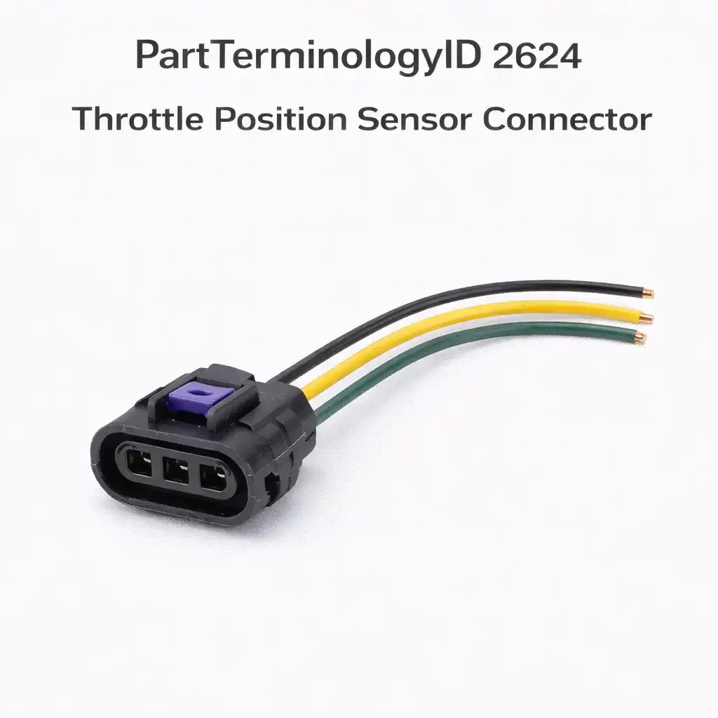
Throttle Position Sensor Connector (PartTerminologyID 2624):Sensor Generations, Terminal Count Splits, and the Catalog Fields That Prevent Drivability Returns
The throttle position sensor connector is one of the most consequential connectors in the engine management system. A failed or poorly connected throttle position sensor produces drivability symptoms that span the full range from subtle to catastrophic: rough idle, hesitation on acceleration, erratic throttle response, limp-home mode activation, and in drive-by-wire applications a complete loss of throttle control that prevents the vehicle from being driven at all. The urgency of these symptoms means buyers in this category are ordering under pressure, often with a vehicle that is already in the shop.
PartTerminologyID 2624 covers the connector that serves the throttle position sensor on both traditional cable-operated throttle bodies and modern electronic throttle control, or drive-by-wire, applications. These two sensor types share a PartTerminologyID but differ in circuit count, connector design, and catalog complexity. The cable-operated TPS is a potentiometer that outputs a variable voltage to the ECM. The electronic throttle body sensor is a dual-track position sensor that outputs two independent signals for redundancy. These are different sensors with different connectors, and the catalog must handle them as different products.
This guide covers PartTerminologyID 2624 in full: what each sensor generation does, where the variant complexity originates, what catalog fields prevent returns, and what listing language gives buyers and technicians what they need to order correctly under time pressure.
PCdb Status for PartTerminologyID 2624
PartTerminologyID
◦ 2624 in both current PIES 7.2 / PCdb and future PIES 8.0 / PCdb 2.0. No change on migration.
Terminology Name
◦ Throttle Position Sensor Connector. No rename in PIES 8.0.
Category
◦ Engine
SubCategory
◦ Fuel Delivery
Status
◦ Active in both schema versions.
The Engine / Fuel Delivery placement reflects the throttle position sensor's role in fuel metering control. The TPS is the primary input the ECM uses to determine how much fuel to inject and when to shift the transmission on vehicles with electronic transmission control. It is not a mechanical fuel delivery component, but its signal is central to fuel delivery calibration, which explains the subcategory placement.
The terminology name covers both sensor generations under one PartTerminologyID. Both sensors measure throttle valve position and both connectors serve the sensor at the throttle body. The terminal count and circuit function split between generations must be captured in the fitment data, not separated into different PartTerminologyIDs. That is where most catalog errors in this category originate.
What the Throttle Position Sensor Does and Why Connector Accuracy Matters
Cable-Operated TPS: The Potentiometer Design
The cable-operated throttle position sensor is a rotary potentiometer mechanically coupled to the throttle shaft. As the accelerator pedal is pressed, a cable rotates the throttle shaft, and the TPS tracks this rotation, outputting a variable voltage proportional to throttle plate angle. At closed throttle the output is typically around 0.5 volts; at wide-open throttle it rises to 4.5 volts or higher. The ECM reads this voltage to calculate throttle position, rate of opening for acceleration enrichment, and idle position for idle air control compensation. On vehicles with electronic transmission control, the TPS signal also schedules shift points.
The cable-operated TPS connector typically carries three circuits: reference voltage from the ECM (five volts), signal output from the potentiometer wiper, and sensor ground return. This three-terminal design covers most cable-operated applications from the OBD2 era through the mid-2000s on domestic platforms and through the early 2010s on some import applications. Loss of any single terminal produces a distinct failure mode, ranging from zero-output sensor faults to voltage offset errors that cause drivability symptoms difficult to diagnose without circuit measurement.
Electronic Throttle Control: The Dual-Track TPS
Electronic throttle control eliminates the mechanical cable between the pedal and throttle plate. An electric motor integrated into the throttle body opens and closes the plate on ECM command. The TPS in an ETC application monitors actual plate position and feeds it back to the ECM, which compares it to commanded position and corrects any deviation. Because an uncommanded throttle opening is a safety hazard, ETC systems require a redundant throttle position signal. A dual-track TPS design produces two independent voltage outputs from separate potentiometer elements on the same shaft. The ECM monitors both continuously and activates a safe-mode strategy if the signals disagree beyond a calibrated threshold.
The dual-track ETC TPS carries five or six terminals: reference voltage, track one signal, track two signal, independent grounds for each track, and in some designs a motor position feedback circuit. These are different circuits on different terminal assignments from the cable-operated connector. The five or six-terminal ETC connector is not interchangeable with the three-terminal cable-operated connector even when both are mounted on throttle bodies that appear physically similar.
THE GENERATION SPLIT IS THE PRIMARY CATALOG PROBLEM
Cable-operated TPS and electronic throttle control TPS connectors are not interchangeable. Both mount on throttle bodies. Both measure throttle plate position. Both fall under PartTerminologyID 2624. A three-terminal cable-operated TPS connector ordered for an ETC application will not mate with the ETC sensor, and even if it physically seated, it would leave two or three ETC circuits unconnected. The cable-operated versus ETC split must be the primary catalog field, above terminal count, because it determines what the connector is for, not merely how many terminals it has.
Terminal Count Across TPS Generations
Terminal count is the most reliable differentiator buyers can verify against their original connector before ordering. The count follows the sensor generation, but the mapping is not one-to-one, because some cable-operated applications used four terminals by adding a second ground or an idle switch circuit, and some ETC applications vary between five and six terminals depending on the design.
Three-Terminal Cable-Operated TPS
The three-terminal connector is the standard cable-operated TPS design. Reference voltage in, signal output, and sensor ground. This is the dominant connector in the cable-operated TPS category and covers most domestic applications from the OBD1 transition period through the mid-2000s and most import applications that retained cable-operated throttle systems into the 2010s. The three-terminal design is widely cataloged and widely available in the aftermarket, which means the primary risk in this segment is not availability but incorrect terminal assignment, specifically swapping the reference voltage terminal with the signal output terminal during installation, which produces a reversed voltage relationship that damages the sensor.
Four-Terminal Cable-Operated TPS
Some cable-operated TPS designs added a fourth terminal to carry either a dedicated idle switch signal or a second ground path. The idle switch variant was common on certain GM applications and some import applications where the ECM required a discrete closed-throttle signal in addition to the analog voltage output from the potentiometer. The second ground variant was used on applications where the ECM specification called for an isolated ground path for the TPS signal relative to the ground shared with other sensors on the same reference voltage supply.
A four-terminal connector is not interchangeable with a three-terminal connector for the same application. Installing a three-terminal connector on a four-terminal application leaves the idle switch or second ground circuit disconnected. On applications where the idle switch is required for closed-throttle fuel cut strategy, a disconnected idle switch produces incorrect fuel delivery during deceleration.
Five-Terminal Electronic Throttle Control TPS
The five-terminal ETC TPS connector is the most common ETC connector design on domestic applications and on many import applications that adopted electronic throttle control from the early 2000s onward. The five terminals carry reference voltage, track one signal, track two signal, and two ground circuits, one for each signal track. The two independent grounds prevent ground offset on one track from affecting the other track, which is important for the ECM's comparison logic that detects sensor faults by comparing the two track outputs.
The five-terminal ETC connector appears on a wide range of applications including GM LS-series engines with ETC, Ford EcoBoost and modern EFI applications, Chrysler Hemi and Pentastar applications with electronic throttle, and most Toyota and Honda applications from the early 2000s onward. The dominant presence of five-terminal ETC connectors across major domestic and import platforms makes this the highest-volume ETC connector in the aftermarket, but it does not mean all five-terminal ETC connectors are interchangeable. The housing profile and terminal design vary across OEM connector families even at the same five-terminal count.
Six-Terminal Electronic Throttle Control TPS
The six-terminal ETC connector adds a motor position feedback or throttle motor supply circuit to the five-terminal set. It appears on European applications and on some domestic designs where the motor control circuit is integrated into the TPS connector. The sixth terminal carries a circuit that would be unconnected if a five-terminal connector were substituted.
The Complete Variant Universe for PartTerminologyID 2624
1. Sensor Generation and Throttle System Type
Sensor generation and throttle system type are the primary filters above terminal count. Two connectors with the same terminal count from different generations are electrically incompatible because the circuit functions assigned to those terminals differ between generations.
• Cable-operated TPS, 3-terminal. The dominant cable-operated design. Reference voltage, signal output, sensor ground.
• Cable-operated TPS, 4-terminal. Adds idle switch or second ground. Specific to applications that required the additional circuit.
• Electronic throttle control TPS, 5-terminal. The dominant ETC design. Dual-track outputs with independent grounds.
• Electronic throttle control TPS, 6-terminal. Adds motor feedback or motor supply circuit. European and some domestic ETC applications.
Sensor generation must appear in the title alongside terminal count. A listing that states 3-terminal TPS connector without noting cable-operated or electronic throttle will be ordered by buyers on three-terminal applications of both types if any three-terminal ETC design exists on the platform, and it will confuse buyers on five-terminal ETC applications who search for a TPS connector and receive a result without a generation note.
2. Connector Body Shape and Throttle Body Interface
• Compact rectangular housing. The most common domestic cable-operated TPS connector profile. Delphi and Packard connector families. Short, flat housing with a push-tab latch. Common on GM, Ford, and Chrysler cable-operated throttle body applications.
• Square or blocky housing. Common on some import cable-operated TPS applications. Toyota and Honda cable-operated throttle bodies used a slightly more square profile on certain engine families compared to domestic rectangular designs.
• Larger rectangular housing. ETC applications require more terminals, and the connector housing is correspondingly larger to accommodate the additional terminal cavities while maintaining adequate wall thickness between cavities for structural integrity.
• Angled or offset housing. Some throttle body designs mount the TPS sensor at an angle relative to the harness routing, requiring the connector to exit at an angle to avoid harness stress. Note wire entry angle on these applications.
• Weatherproof housing with gasket seal. Some ETC TPS connectors, particularly on applications exposed to more direct underhood water splash, use a weatherproof housing with a face seal gasket. Not interchangeable with open-face connector designs at matching terminal counts.
3. OEM Connector Family
The OEM connector family identifies the housing profile and terminal design with the precision needed to distinguish connectors that appear similar at a glance but differ in latch design, housing depth, or terminal retention geometry.
• Delphi or Packard. Dominant domestic family for cable-operated TPS applications. The Delphi Metri-Pack 150 series appears on many GM cable-operated applications.
• Bosch. European applications and domestic applications using Bosch throttle bodies. Distinctive latch geometry.
• Denso. Primary supplier for Toyota and Honda ETC throttle body sensors from the early 2000s onward.
• Sumitomo. Honda and some Toyota cable-operated and ETC applications. Sumitomo-specific terminal and latch designs.
• TE Connectivity or AMP. BMW, Volkswagen Group, and some Ford ETC throttle body sensors.
• Ford-proprietary. Coyote, EcoBoost, and Modular engine ETC applications. Differs from Bosch and TE Connectivity designs despite similar external appearance.
4. Wire Entry Angle
The throttle body sits in the engine's intake path, and harness routing at the throttle body varies by engine orientation and intake manifold design. The wire entry angle at the TPS connector determines whether the harness can exit cleanly without stress at the connector body.
• Straight entry. The most common orientation. Wire bundle exits in line with the connector axis. Standard on most domestic applications where the harness approaches the throttle body along the intake manifold.
• 90-degree entry. Wire bundle exits perpendicular to the mating face. Used on applications where the harness must route along the throttle body or intake manifold face immediately after the connector, typically on transversely mounted engines with limited clearance between the throttle body and the firewall.
• Angled entry. Some connectors use an entry angle between straight and 90 degrees to accommodate specific harness routing geometries on compact engine bays.
On transversely mounted four-cylinder and V6 engines in compact engine bays, a straight-entry connector on a 90-degree-entry application places the harness against the throttle body or intake manifold where heat and vibration stress the connector over time.
5. Seal Type and Environmental Protection
The TPS connector is mounted on the throttle body, which is in the engine intake air path. Unlike exhaust-mounted sensors, the TPS is not exposed to high heat, but it is exposed to underhood moisture, oil mist, and in some installations direct water splash. Sealing requirements vary by application and mounting location.
• Individual wire seals with peripheral face seal. Standard on modern ETC TPS connectors. The dual-seal design prevents moisture ingress from both the harness side and the sensor side.
• Individual wire seals only. Present on some cable-operated TPS connectors. Seals the wire entries but leaves the connector face exposed. Adequate for most throttle body mounting locations.
• Unsealed. Present on older cable-operated connectors. Note explicitly.
• Weatherproof with integral gasket. Present on some ETC applications with specific moisture exposure requirements. The integral gasket provides a higher level of protection than individual wire seals alone.
6. Pigtail Length and Wire Gauge
• Pigtail length. State in inches. TPS connector pigtails are typically short because the TPS is mounted directly on the throttle body and the nearest harness branch is close. Standard lengths are commonly 6 to 10 inches. Long pigtails of 14 inches or more may be required on applications where the main harness branch is routed away from the throttle body to avoid heat sources.
• Wire gauge. TPS circuits carry reference voltage and analog signal, both low-current signals. Wire gauge is typically 20 or 22 AWG for signal and reference circuits. Note gauge when stated in the supplier data.
• Wire colors. Note when colors match OE convention. TPS connector wire color matching is a practical aid for technicians splicing a new pigtail into the harness, particularly on three-terminal connectors where the polarity of the reference voltage and signal circuits must be correctly matched to avoid sensor damage.
The Cable-Operated to ETC Transition: The Most Consequential Platform Split
The transition from cable-operated to electronic throttle control occurred at different model years across different platforms, engine families, and trim levels. This staggered transition is the primary catalog complexity in this category. Some platforms transitioned at a clean calendar year boundary. Others transitioned mid-model-year, requiring a production date qualifier. Some offered both cable-operated and ETC variants in the same model year on different engine options, making engine specification mandatory in the fitment data.
The fitment data must capture the throttle system type as a hard split, not a qualifier. A qualifier that says electronic throttle assumes buyers know whether their vehicle has ETC. Many do not. The listing must communicate the distinction clearly enough that a buyer who does not know their throttle system type can determine it before ordering.
How to Help Buyers Identify Their Throttle System Type
How to Help Buyers Identify Their Throttle System Type
The listing must give buyers the means to identify their throttle system type without requiring prior technical knowledge. The following content helps buyers self-identify:
• Terminal count verification. Instruct the buyer to count the terminals on their original connector. Three or four terminals indicates cable-operated TPS. Five or six terminals indicates ETC TPS. This is the fastest visual verification available without tools.
• Accelerator cable presence. A cable-operated throttle system has a visible accelerator cable attached to the throttle body. An ETC throttle body has no cable. This is visible without tools from above the engine on most applications.
• Throttle body appearance. ETC throttle bodies typically have a motor housing visible on one side of the throttle body that is absent on cable-operated designs. This is visible on most applications.
• VIN-based lookup. Direct buyers to confirm throttle system type through the vehicle VIN and OEM parts lookup before ordering if the above checks are not conclusive.
THE VERIFICATION PROBLEM
Most buyers searching for a TPS connector know their vehicle but not their throttle system generation. They search by year, make, model, and engine. The catalog must do the work of translating vehicle identification into throttle system type, because the buyer cannot be expected to know that their 2003 Silverado 5.3 has a cable-operated throttle while the 2004 has ETC. That translation is the catalog data's job. Without it, the listing relies on the buyer knowing something the listing never told them.
Platform Notes for High-Volume Applications
GM LS-Series Engines
The GM LS engine family is one of the most important TPS connector catalog splits in the domestic aftermarket. LS1 applications from 1997 to 2002 used cable-operated throttle with a three-terminal Delphi connector. Beginning in 2003 and spreading through 2004 and 2005, GM transitioned to ETC using a five-terminal connector. The LS1 cable-operated connector and the LS2-and-later ETC connector are completely different parts. The LS swap market adds complexity because a buyer installing an LS engine in a non-OEM vehicle may not know the production year or throttle system type. Listings must separate the cable-operated LS1-era connector from the ETC LS2-and-later connector by engine designation.
GM Full-Size Truck Applications
GMT800 full-size trucks transitioned from cable-operated to ETC at different points by engine. The 4.8, 5.3, and 6.0-liter V8s completed the ETC transition by 2003 or 2004. The Vortec inline-six retained cable-operated systems longer on some fleet applications. Application data must note the engine and model year precisely to avoid grouping cable-operated and ETC in the same fitment row.
Ford Coyote and EcoBoost Applications
Ford Coyote 5.0-liter and EcoBoost applications are exclusively ETC throttle body designs and use Ford-proprietary five-terminal ETC TPS connectors. The Ford ETC connector family differs from GM ETC connectors in housing profile and terminal design even at the same five-terminal count. Listings for Ford ETC TPS connectors must note the Ford-proprietary connector family and confirm ETC application to prevent buyers from ordering GM-family ETC connectors for Ford applications based on terminal count alone. Ford's earlier Modular 4.6-liter and 5.4-liter engines span the cable-operated to ETC transition at different points depending on application, creating production year splits that must be represented in the catalog.
Toyota and Lexus Applications
Toyota transitioned to ETC at a pace that varied by engine family. The 2GR-FE V6 in Camry, Highlander, and RAV4 from 2006 onward uses a Denso ETC connector with five terminals. The earlier 1MZ-FE V6 used in Camry and Highlander through 2006 used a cable-operated three-terminal connector. A single fitment row covering both engine generations will produce the wrong connector on every order on the wrong side of the change. Lexus applications on 3GR-FSE and similar engine families use Denso ETC connectors specific to Lexus throttle body designs; note the engine family on Lexus listings.
Honda and Acura Applications
Honda K-series four-cylinder engines retained cable-operated throttle on some variants through 2005 before transitioning to ETC. Honda J-series V6 engines in the Accord and Odyssey transitioned at similar points. The Sumitomo or Honda-proprietary ETC TPS connector differs in housing profile from the cable-operated connector on the same platforms. Acura applications on the TL, MDX, and RDX follow similar timelines. Acura ETC connectors are Sumitomo or Honda-proprietary designs that must not be substituted with domestic flat-tab connectors at matching terminal counts.
Chrysler Hemi and Pentastar Applications
Chrysler Hemi 5.7 and 6.4-liter and Pentastar 3.6-liter applications use ETC throttle bodies with five-terminal Mopar or Delphi connectors. Earlier Chrysler applications using the Magnum V8 series may have cable-operated throttle depending on model year. The Hemi name alone does not confirm ETC status, as some early Hemi applications predated ETC adoption. Note engine family and confirm ETC status in the application data.
European Applications: BMW, Volkswagen Group, and Mercedes-Benz
BMW and Mercedes-Benz implemented ETC in the late 1990s and Volkswagen Group followed in the early 2000s. European ETC connectors use Bosch or TE Connectivity families that differ from domestic ETC connectors in housing profile and latch design. BMW uses Bosch ETC connectors with five or six terminals depending on generation. Volkswagen Group applications including Audi use Bosch or VW-proprietary connectors at five or six terminals depending on whether the motor feedback circuit is integrated. Note the connector family explicitly on all European listings.
Catalog Fields That Reduce Returns for PartTerminologyID 2624
Core Identification Fields
Throttle System Type
◦ Cable-operated TPS or Electronic Throttle Control (ETC) TPS. Required in the title. This is the primary filter above terminal count.
Terminal Count
◦ 3-terminal, 4-terminal, 5-terminal, or 6-terminal. Required in the title alongside throttle system type.
Connector Body Shape
◦ Compact rectangular, Square, Larger rectangular for ETC, Angled, or Weatherproof with gasket. Written description required.
OEM Connector Family
◦ Delphi, Bosch, Denso, Sumitomo, TE Connectivity, Ford-proprietary, or other. Required on import and European applications and on domestic ETC applications where multiple connector families co-exist.
Wire Entry Angle
◦ Straight, 90-degree, or Angled. Required on compact engine bay applications.
Generation and Application Fields
Throttle System Generation Note
◦ For platforms mid-transition between cable-operated and ETC, note the production year range or engine variant this connector serves. Required on any platform where both throttle system types appear in the same year, make, model, and engine row.
Engine Variant Note
◦ Required when the throttle system type varies by engine option within the same model year and platform.
Verification Guidance
◦ Include one sentence instructing the buyer to count connector terminals to verify throttle system type before ordering. Required on any listing that covers a platform with both cable-operated and ETC variants in the catalog.
Seal, Wire, and Pigtail Fields
Seal Type
◦ Wire seals with face seal, Wire seals only, Weatherproof with gasket, or Unsealed.
Pigtail Length
◦ State in inches.
Wire Gauge
◦ State in AWG. Typically 20 or 22 AWG for TPS circuits.
Wire Colors
◦ Note when matching OE convention. Aids correct polarity alignment on installation.
Compatibility Statement
◦ One sentence. Throttle system type, terminal count, connector family, and what this connector does not fit.
The Most Common Listing Mistakes for PartTerminologyID 2624
Mistake 1: Throttle System Type Not Stated
This is the primary return driver. A listing that says 5-terminal TPS Connector without stating Electronic Throttle Control will be ordered by buyers on cable-operated applications who assume it matches their sensor. ETC belongs in the title on every ETC listing. Cable-operated belongs in the title on every cable-operated listing.
Mistake 2: Terminal Count Not Stated
Terminal count is the fastest verification step available. Counting terminals on the original connector confirms whether the replacement matches before ordering. Terminal count belongs in the title alongside throttle system type on every TPS connector listing.
Mistake 3: Cable-Operated to ETC Transition Not Split at the Production Year
A single fitment row covering a production run that spans both throttle system types will ship the wrong connector to buyers on one side of the transition on every such order. The transition year is the split point. Two listings required, not one listing with a disclaimer.
Mistake 4: Same Platform, Different Engine, Different Connector Not Noted
On platforms where engine options used different throttle systems in the same model year, the engine must be specified in the fitment data. A GM full-size truck listing that does not specify whether it fits the cable-operated Vortec six or the ETC V8 will produce wrong-connector shipments on every engine-specific order.
Mistake 5: Import Connector Family Not Identified
Denso, Sumitomo, Bosch, and TE Connectivity connectors use housing profiles that are not interchangeable with domestic Delphi connectors at matching terminal counts. Omitting the connector family from import listings allows domestic substitution. The housing will not mate with the import throttle body sensor interface.
Mistake 6: Verification Guidance Absent on Mixed-System Platforms
On platforms where both cable-operated and ETC connectors list to overlapping fitment rows, the buyer needs explicit guidance before ordering. Without terminal count verification guidance, wrong-connector orders from buyers who do not know their throttle system type are predictable and preventable.
Mistake 7: Wire Color Notes Absent on Three-Terminal Applications
The reference voltage input and signal output on a three-terminal connector use similar wire gauge and can appear similar. Reversing them during installation damages the sensor and may damage the ECM reference voltage circuit. Wire color notes give technicians a verification reference that prevents this error.
Marketplace-Ready Listing Standards for PartTerminologyID 2624
Required Title Elements
Cable-operated three-terminal domestic application:
Throttle Position Sensor Connector, Cable-Operated, 3-Terminal, Delphi-Style, Fits GM Vortec
ETC five-terminal domestic application:
Throttle Position Sensor Connector, Electronic Throttle Control, 5-Terminal, Fits GM LS ETC
Toyota ETC application:
Throttle Position Sensor Connector, Electronic Throttle Control, 5-Terminal, Denso, Fits Toyota 2GR-FE
Ford ETC application:
Throttle Position Sensor Connector, Electronic Throttle Control, 5-Terminal, Ford ETC, Fits Coyote 5.0 / EcoBoost
Required Bullet Points
• THROTTLE SYSTEM: Cable-operated TPS or Electronic Throttle Control (ETC) TPS. Required on every listing.
• TERMINAL COUNT: 3, 4, 5, or 6 terminals. Required.
• HOUSING SHAPE: Compact rectangular, Square, Larger rectangular, Angled, or Weatherproof with gasket.
• OEM CONNECTOR FAMILY: Delphi, Bosch, Denso, Sumitomo, Ford-proprietary, or other.
• WIRE ENTRY: Straight, 90-degree, or Angled. Note on compact engine bay applications.
• SEAL TYPE: Wire seals with face seal, Wire seals only, Weatherproof, or Unsealed.
• PIGTAIL LENGTH: State in inches.
• WIRE GAUGE: State in AWG.
• WIRE COLORS: Note when matching OE convention. Reference for polarity alignment during installation.
• VERIFICATION: Count terminals on original connector before ordering. 3 or 4 terminals: cable-operated TPS. 5 or 6 terminals: ETC TPS.
• COMPATIBILITY: One sentence. Throttle system type, terminal count, connector family, and what this connector does not fit.
Compatibility Statement Templates
TEMPLATE A: CABLE-OPERATED THREE-TERMINAL
Fits: Cable-operated throttle body TPS, 3-terminal, compact rectangular Delphi-style housing. Does not fit: 4-terminal cable-operated applications with idle switch circuit. Does not fit: electronic throttle control (ETC) applications (5 or 6-terminal). Verify original connector has exactly 3 terminals before ordering.
TEMPLATE B: ETC FIVE-TERMINAL DOMESTIC
Fits: Electronic throttle control (ETC) TPS, 5-terminal, dual-track sensor design. Does not fit: cable-operated TPS applications (3 or 4-terminal). Does not fit: 6-terminal ETC applications with motor feedback circuit. Verify original connector has exactly 5 terminals and vehicle has electronic throttle control before ordering.
TEMPLATE C: ETC FIVE-TERMINAL IMPORT
Fits: Toyota or Honda electronic throttle control TPS, 5-terminal, Denso or Sumitomo housing. Does not fit: domestic Delphi-style connectors at same terminal count. Housing profile is specific to import throttle body sensor interface. Verify vehicle has ETC throttle body and original connector has 5 terminals before ordering.
FAQ for Throttle Position Sensor Connector (PartTerminologyID 2624)
How do I know if my vehicle has cable-operated throttle or electronic throttle control?
The fastest check is to look at the throttle body under the hood. A cable-operated throttle body has a visible accelerator cable, typically a metal-jacketed cable with a conduit, attached to a lever arm on the throttle shaft. If you see this cable, the vehicle has cable-operated throttle and requires a cable-operated TPS connector. An electronic throttle control throttle body has no accelerator cable attached. The throttle body will have an electric motor housing visible on one side of the body. If you see no cable, the vehicle has electronic throttle control and requires an ETC TPS connector. Counting the terminals on the original connector confirms the result: three or four terminals is cable-operated, five or six terminals is ETC.
Can I use a three-terminal connector on a four-terminal cable-operated application by leaving one terminal empty?
No. The fourth terminal on a four-terminal cable-operated TPS connector carries a circuit that the ECM actively monitors. On applications where the fourth terminal carries the idle switch signal, the ECM uses this signal for closed-throttle fuel cut strategy and for idle quality management. Leaving this terminal disconnected produces incorrect ECM behavior at closed throttle, which may present as rough deceleration, incorrect idle air control, or a stored fault code for the idle switch circuit. The three-terminal and four-terminal connectors are different parts for a reason. Order the connector that matches your terminal count.
What happens if I install a cable-operated TPS connector on an ETC throttle body?
A cable-operated connector will not correctly mate with an ETC throttle body because the sensor geometry, terminal count, and housing profile differ. On most modern ETC applications the housing will not latch at all, presenting the mismatch as a connector that does not seat rather than a drivability problem. If it partially seated, the ECM would immediately detect a fault because the dual-track signals required for ETC operation are absent.
Why do some TPS connectors have wire color notes and others do not?
Color notes matter most on three-terminal cable-operated connectors because the reference voltage input and signal output use similar voltage levels and wire gauges. Reversing them applies the ECM reference output to the signal input, damaging both the sensor and potentially the ECM reference circuit. On five-terminal ETC connectors the asymmetric housing and higher terminal count make polarity errors less likely, though color notes still serve as a useful final verification step.
My vehicle stored a TPS fault code after I replaced the connector. What should I check?
The most common causes are a terminal not fully seated in the new housing; reference voltage and signal wires transposed during the splice; a connector from a different variant of the same family with slightly different terminal depth that does not fully engage the sensor body; or on ETC applications, the correct terminal count but a different OEM connector family that does not fully engage the dual-track sensor interface. Verify terminal seating, verify wire color alignment, and confirm the connector family matches the OEM specification for your throttle body.
Catalog Quality Checklist for PartTerminologyID 2624
1. State throttle system type in the title. Cable-operated TPS or Electronic Throttle Control ETC TPS. Required on every listing.
2. State terminal count in the title alongside throttle system type. 3, 4, 5, or 6 terminals.
3. Describe connector body shape. Compact rectangular, Square, Larger rectangular, or Weatherproof with gasket.
4. Identify OEM connector family. Required on import, European, and ETC applications where multiple families co-exist.
5. Note wire entry angle on compact engine bay applications.
6. Split cable-operated and ETC applications into separate listings on any platform that spans both throttle system generations.
7. Note the production year or engine variant split on platforms that transitioned mid-generation.
8. Specify engine option when throttle system type varies by engine within the same model year and platform.
9. Document seal type. Note weatherproof with gasket when applicable.
10. Specify pigtail length in inches.
11. State wire gauge in AWG and note wire colors when matching OE convention.
12. Include terminal count verification guidance. Instruct the buyer to count terminals before ordering on any mixed-system platform.
13. Write a compatibility statement. Throttle system type, terminal count, connector family, and what this connector does not fit.
Final Thoughts
The throttle position sensor connector category is anchored by one fundamental challenge: a PartTerminologyID that covers two different sensor generations, each with its own circuit map, terminal count range, and connector design. The cable-operated TPS and the ETC TPS are different sensors that produce different connectors, and the catalog must represent them as different products even though both fall under PartTerminologyID 2624.
The transition from cable-operated to ETC happened at different years on different platforms, at different engine variants within the same platform year, and in some cases mid-model-year. That uneven transition schedule is the structural source of the fitment complexity in this category. Buyers do not always know where their vehicle falls on that transition schedule, and the listing must give them the information they need to find out before they order.
Throttle system type in the title. Terminal count in the title. Connector family on import and ETC applications. Production year or engine variant split on transitional platforms. Terminal count verification guidance in the listing body. One compatibility sentence at the close. That is the complete catalog structure for PartTerminologyID 2624, applied consistently to every listing in the category.