Radio Power Connector (PartTerminologyID 2612):Harness Interface Types, Circuit Functions, and the Catalog Fields That Prevent Misshipments
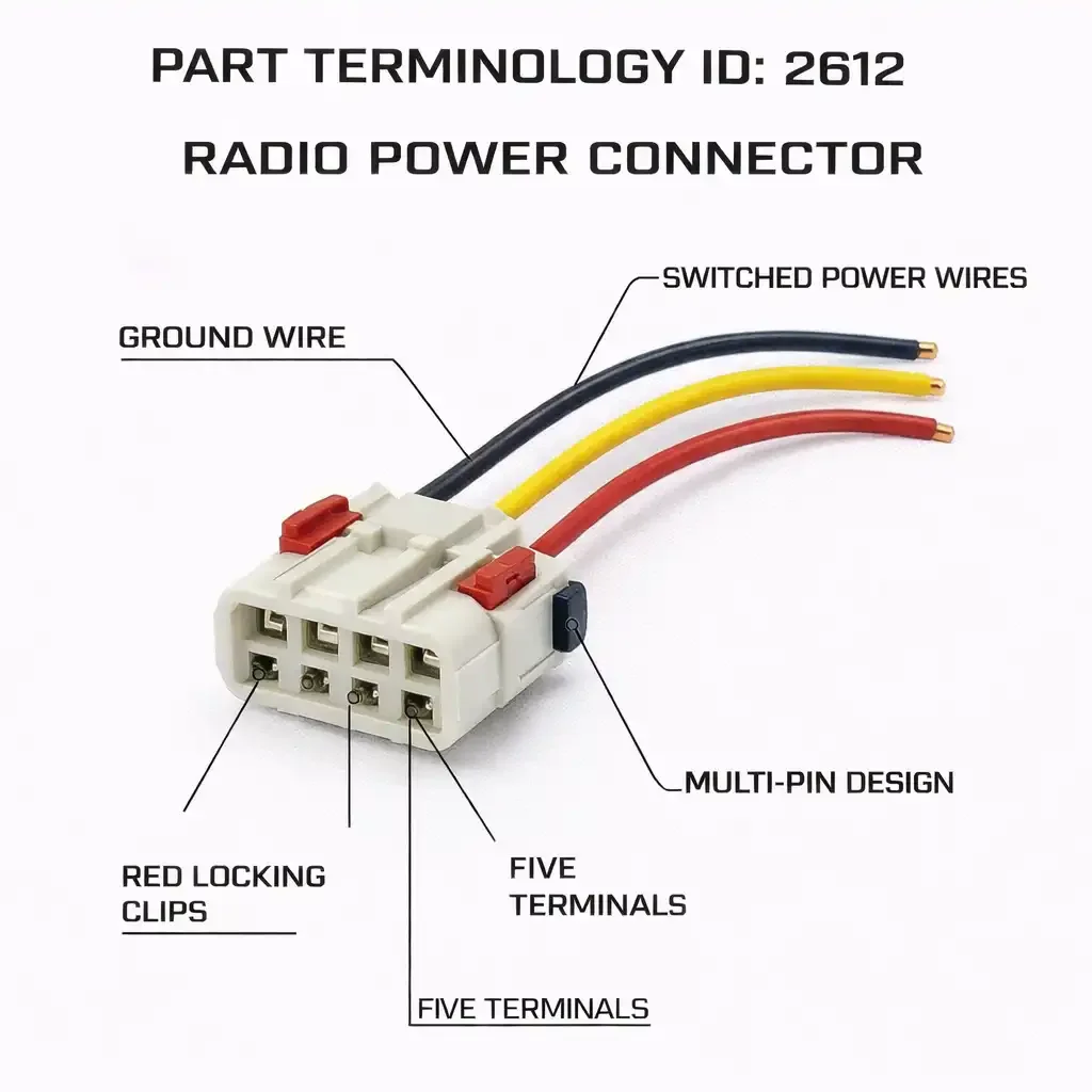
The Radio Power Connector serves the connector that delivers power from the vehicle wiring harness to the radio. It does not cover the full radio harness assembly, antenna connector, speaker output connectors, or amplifier connectors. The power connector only. That specificity is both the catalog advantage of PartTerminologyID 2612 and the source of buyer confusion that generates returns when the listing does not make the scope explicit.
This guide covers PartTerminologyID 2612 in full: what circuits the connector carries, how the design varies across OEM harness generations, what catalog fields prevent returns, and what listing language gives buyers enough to order correctly the first time.
PCdb Status for PartTerminologyID 2612
PartTerminologyID
◦ 2612 in both current PIES 7.2 / PCdb and future PIES 8.0 / PCdb 2.0. No change on migration.
Terminology Name
◦ Radio Power Connector. No rename in PIES 8.0.
Category
◦ Body
SubCategory
◦ Audio
Status
◦ Active in both schema versions.
The Body / Audio placement is accurate. Sellers should ensure this connector appears in audio and radio accessory searches, not only in general electrical connector searches. Buyers sourcing radio harness components typically search from the audio system angle, not the connector category angle.
What the Radio Power Connector Carries
The radio power connector is the harness-side connection point for the power and control circuits the head unit requires. The circuit count determines the terminal count, which is the primary differentiator across connector variants.
The Core Circuit Set
Every radio power connector carries some combination of the following circuits regardless of vehicle era or OEM:
• Constant battery power. A direct battery feed that remains live regardless of key position. Powers the radio memory, clock, and station preset storage. Typically fused upstream. This is a constant 12-volt feed, not key-switched.
• Switched ignition power. A key-switched 12-volt supply that powers the radio amplifier and main operating circuits when the key is in the accessory or run position. The radio turns on and off with the key through this circuit.
• Accessory or ACC power. On some designs a separate accessory circuit distinct from the switched ignition feed. Powers the radio in accessory position only, not in run position with the engine running on some older designs.
• Ground. One or more chassis ground return circuits. Some radios use multiple ground paths to prevent noise injection from sharing a single ground return with other components.
• Illumination circuit. A dimmer-controlled 12-volt feed from the instrument panel lighting circuit that tells the radio display to dim when the headlights are on. Not present on all designs.
• Amplifier remote turn-on. A switched output from the radio that signals an external amplifier to power on when the radio is active. Present when the factory system includes an external amplifier. Absent on base audio systems.
The minimum terminal count is three: constant power, switched power, and ground. Modern connectors carry six to ten terminals when illumination, amplifier remote, and additional ground paths are included. The terminal count difference between a base audio connector and a premium audio connector for the same platform is a hard compatibility break.
Premium Audio System Circuits
Vehicles equipped with factory premium audio systems, Bose, Harman Kardon, JBL, Burmester, and similar branded systems, often route additional circuits through the radio power connector that are not present on base audio connectors for the same platform.
• Amplifier control bus. A data signal rather than a simple remote turn-on, used on systems where the external amplifier requires configuration or equalization data from the head unit. Adds terminals and changes the circuit function of those terminals compared to the base connector.
• Steering wheel audio control circuit. On some designs the steering wheel audio control signals route through the radio power connector rather than through a separate harness connection. This adds terminals to the power connector that carry CAN bus or resistive ladder signals from the steering wheel controls.
• DSP or signal processor data circuit. Vehicles with factory digital signal processors between the head unit and the amplifiers may route DSP configuration data through the radio power connector on some designs.
Premium audio connectors must be identified separately from base audio connectors for the same vehicle platform. The additional circuits in the premium connector carry signals that the base audio wiring does not provide, and the base connector will not support an aftermarket installation on a premium audio vehicle without additional interface modules. The catalog must separate base and premium audio applications into distinct listings.
BASE VS. PREMIUM AUDIO: THE PRIMARY CATALOG SPLIT
The most common radio power connector return is a buyer on a premium audio vehicle who receives the base audio connector for the same platform. Both connectors list to the same year, make, and model. The terminal counts differ by three or more terminals depending on what premium circuits are present. The listing failed to split base and premium audio applications. Two listings, not one, is the correct catalog structure for any platform available with both audio configurations.
OEM Harness Interface Standards and What They Mean for Catalog Data
The radio power connector is part of a larger OEM harness interface that connects the radio to the vehicle wiring system. The harness interface standard determines the physical connector family, the terminal design, and the circuit map that applies to any given application. Identifying the harness interface standard in the listing is more useful to buyers than describing the connector housing alone, because the standard name is how buyers and installers reference compatibility.
GM Class 2 and LAN Bus Connectors
GM applications from the late 1990s onward incorporated Class 2 serial data communication in the radio connector alongside standard power and ground circuits. The Class 2 bus carries vehicle speed data, door chime data, and other vehicle information to the radio. The GM Class 2 connector includes terminals for this data circuit that are absent from pre-Class 2 GM connectors. A buyer who installs a non-Class 2 connector on a Class 2 application loses vehicle data display functions in the radio.
Ford SYNC and APIM Connectors
Ford SYNC applications use a radio connector incorporating APIM communication circuits alongside standard power and ground supply. APIM data circuits are absent from non-SYNC Ford connectors for the same platform and model year. Ford applications with and without SYNC use different connector designs on the same platform. The catalog must split at the SYNC equipment line.
The Complete Variant Universe for PartTerminologyID 2612
1. Terminal Count
Terminal count is the primary differentiator for radio power connectors and the field most commonly absent from aftermarket listings. The range across all applications is wide, and the count on any given platform is determined by the audio system configuration.
• 3 to 4 terminal. Minimum power circuit configuration. Constant power, switched power, ground. Present on some older applications with simple audio systems.
• 6 to 8 terminal. Standard modern configuration with illumination, amplifier remote, and dual ground paths. Covers most base audio applications on domestic and import platforms from the OBD2 era onward.
• 10 to 12 terminal. Premium audio and data-bus-equipped applications. Includes amplifier control circuits, steering wheel control data, and vehicle data bus terminals in addition to the core power circuits.
• 16 terminal. ISO 10487 standard A connector. European and ISO-standard applications. The full ISO A connector carries power, ground, illumination, and four speaker output pairs in a single 16-pin housing.
Terminal count must appear in the listing title and item specifics. On platforms available with base and premium audio configurations, the terminal count difference is the most reliable differentiator buyers can verify against their original connector before ordering.
2. Connector Body and Locking Mechanism
• Standard push-tab rectangular housing. Most common on domestic applications.
• ISO A housing. Wider and shorter than domestic rectangular housings. Standard across European applications.
• Double-locking housing. Primary latch plus secondary over-locking clip for higher-vibration locations.
• Slide-lock housing. Collar releases the latch. Common on some import applications.
3. Wire Gauge and Current Capacity
The constant power and switched power circuits in the radio connector carry the full operating current of the head unit and, on premium audio vehicles, the startup current for the external amplifier. Wire gauge must be appropriate for the current load.
• 18 AWG. Adequate for base audio systems where the radio is the only load on the power circuit. Typical for older applications with lower-power head units.
• 16 AWG. Standard for modern head units with higher output stages and for applications where the amplifier remote circuit draws from the same wire gauge as the power circuits.
• 14 AWG on constant power feed. Required on premium audio applications where the constant power feed must sustain the memory and processing loads of a complex head unit with multiple DSP channels.
Wire gauge must be stated for the power circuit wires. An undersized constant power wire will run warm under sustained radio operation, accelerating insulation degradation behind the dashboard where temperatures are already elevated.
4. Pigtail Length
• Short, 6 to 8 inches. Appropriate where the splice point is within the dash cavity immediately behind the radio opening. Common on applications where the factory harness exits the dash with minimal slack.
• Standard, 10 to 14 inches. The most common aftermarket offering. Provides enough length to route the pigtail out of the dash cavity and splice into the main harness at the kick panel or dash harness junction.
• Long, 16 inches and above. Required when the repair extends further into the dash harness due to heat damage or corrosion, or when the radio location is deeper in the dash than standard.
State pigtail length in inches on every listing. Dash harness repairs are performed in confined spaces with limited access, and a pigtail that is two inches short cannot be extended easily once the dash is partially reassembled.
5. Audio System Configuration
• Base audio. Lower terminal count. No amplifier control bus, no data bus terminals.
• Premium audio with external amplifier. Higher terminal count. Amplifier remote or amplifier control bus circuit included.
• With SYNC or infotainment data system. Includes vehicle data bus terminals. Required for Ford SYNC, GM Class 2, and similar systems.
What PartTerminologyID 2612 Does Not Cover
The radio power connector is one component in a larger radio installation harness. Buyers replacing or installing a radio often need multiple connectors from different PartTerminologyIDs, and a listing for PartTerminologyID 2612 that does not clarify its scope will attract orders from buyers who need the full harness assembly or one of the adjacent connectors.
• Full radio wiring harness. The complete harness assembly that includes power, speaker, and antenna adapters as a combined unit. A buyer who needs the full harness and receives only the power connector will have the power connection but will still need the speaker output connector and antenna adapter before the radio installation is complete.
• Speaker output connector. The connector that carries the speaker output signals from the radio or amplifier to the speaker wiring. A separate part from the power connector even when both are part of the same harness plug assembly at the back of the radio.
• Antenna adapter. The connector that adapts the factory antenna cable to the aftermarket radio's antenna input. Not part of the power connector assembly.
• Amplifier harness connector. On premium audio vehicles, the amplifier has its own power and signal connectors separate from the radio power connector. The radio power connector carries the amplifier remote turn-on signal, but the amplifier power supply connector is a different part.
A listing for PartTerminologyID 2612 must state in plain language that this connector serves the radio power supply circuit only. For buyers who need the full radio installation harness, a cross-reference to the applicable full harness assembly is appropriate and reduces the chance of a return from a buyer who expected the complete installation solution.
SCOPE STATEMENT REQUIRED
Every PartTerminologyID 2612 listing should include one sentence stating what this connector covers and what it does not. Example: This connector serves the radio power supply circuit only. It does not include speaker output connectors, antenna adapters, or amplifier harness connections. Buyers who need the complete radio installation harness should reference the full harness assembly for their application.
Platform Notes for High-Volume Applications
GM Truck and SUV Applications
GM full-size truck and SUV applications from the late 1990s through the early 2010s require a base and Bose audio split. The Bose system connector includes the amplifier control circuit and in some cases the steering wheel control data circuit, raising the terminal count above the base connector. Reference the Bose system by name in the split note, as buyers on these platforms typically know their audio system from the window sticker.
Ford F-Series and Mustang Applications
Ford applications require up to three separate radio power connector listings per model year range: base audio without SYNC, base audio with SYNC, and premium Shaker or Sony audio with SYNC. The SYNC split adds vehicle data bus terminals. The premium audio split adds amplifier control circuits. Application data must note both the SYNC status and the audio system level.
Toyota and Lexus Applications
Toyota and Lexus applications use Sumitomo or Toyota-proprietary housings that differ from domestic rectangular connectors at matching terminal counts. Toyota JBL premium audio applications use a different connector from base audio on the same platform. Lexus Mark Levinson applications use their own connector distinct from base Lexus audio. Note the audio system level and the Toyota-specific connector family to prevent domestic connector substitution.
Honda and Acura Applications
Honda and Acura applications use Sumitomo connector families. Premium audio applications including Acura ELS Studio use higher-terminal-count connectors than base audio on the same platform. Honda also changed radio connector designs at the pre-2012 to post-2012 model generation boundary on several platforms, creating a production date split in addition to the audio level split. Application data must address both the audio level and the generation boundary.
Catalog Fields That Reduce Returns for PartTerminologyID 2612
Core Identification Fields
Audio System Configuration
◦ Base audio, Premium audio with external amplifier, or Premium audio with SYNC or data bus. Required in the title and item specifics. This is the primary split above terminal count.
Terminal Count
◦ Exact count. Required in the title and item specifics. For ISO applications, note 16-pin ISO A separately from standard domestic counts.
Connector Body Type
◦ Standard rectangular, ISO A, Double-locking, or Slide-lock. Written description required.
OEM Connector Family
◦ Sumitomo, Toyota-proprietary, Delphi, or ISO 10487. Required on import and ISO-standard applications.
Circuit and Wire Fields
Circuit Content Note
◦ A brief list of what circuits are in the connector. Constant power, switched power, ground, illumination, amplifier remote or control bus, data bus terminals. Allows buyers to verify their application.
Wire Gauge
◦ State AWG for power circuits separately from signal circuits. 18, 16, or 14 AWG for power. 20 or 22 AWG for signal and data bus wires.
Pigtail Length
◦ State in inches.
Scope and Compatibility Fields
Scope Statement
◦ Radio power circuit only. Does not include speaker output, antenna adapter, or amplifier harness connectors.
Compatibility Statement
◦ One sentence. Audio system, terminal count, connector family this connector fits. What it does not fit.
The Most Common Listing Mistakes for PartTerminologyID 2612
Mistake 1: Audio System Configuration Not Stated
Both base and premium audio connectors list to the same year, make, and model on most platforms. The terminal count difference between them is three or more terminals. A listing without audio system configuration in the title ships the wrong count to every buyer on the other configuration. Audio system type belongs in the title.
Mistake 2: Terminal Count Not Stated
Terminal count gives the buyer a physical verification point they can confirm by counting their original connector. It is not a substitute for the audio system configuration note, and the audio system note is not a substitute for it. Both are required in the title.
Mistake 3: Scope Not Stated
A buyer who needs the full harness and receives only the power connector delays their installation. One sentence stating radio power circuit only prevents every such return. It is the most avoidable return in this category.
Mistake 4: SYNC vs. Non-SYNC Not Split on Ford Applications
Ford SYNC connectors include vehicle data bus terminals absent from non-SYNC connectors. A single fitment row without a SYNC note ships the wrong connector to every SYNC or every non-SYNC buyer depending on which the listing describes. Two listings required.
Mistake 5: ISO A Connector Listed Without ISO Designation
The ISO A connector is physically distinct from domestic rectangular connectors at the same pin count. A listing without the ISO A designation attracts domestic connector buyers who see 16-pin and assume compatibility. ISO A must appear in the title.
Mistake 6: Import Connector Family Not Identified
Toyota, Honda, and Lexus connectors use Sumitomo or Toyota-proprietary housings that are not interchangeable with domestic rectangular connectors at matching terminal counts. Omitting the connector family allows domestic substitution. The housing will not mate.
Marketplace-Ready Listing Standards for PartTerminologyID 2612
Required Title Elements
Domestic base audio application:
Radio Power Connector, Base Audio, 8-Terminal, Fits GM Silverado Without Bose
Domestic premium audio application:
Radio Power Connector, Premium Audio, 12-Terminal, Fits GM Silverado With Bose
Ford SYNC application:
Radio Power Connector, With SYNC, 10-Terminal, Fits Ford F-150 SYNC-Equipped
ISO A standard application:
Radio Power Connector, ISO 10487 A, 16-Pin, Fits European ISO-Standard Harness
Required Bullet Points
• AUDIO SYSTEM: Base audio or Premium audio. State the specific premium system name when known (Bose, JBL, Harman Kardon, Mark Levinson).
• TERMINALS: Exact count. Required.
• CONNECTOR TYPE: Standard rectangular, ISO A, Double-locking, or Slide-lock.
• HARNESS STANDARD: ISO A, GM Class 2, Ford SYNC when applicable.
• OEM CONNECTOR FAMILY: Sumitomo, Delphi, or other. Required on import applications.
• CIRCUIT NOTE: Constant power, switched power, ground, illumination, amplifier remote if present.
• WIRE GAUGE: AWG for power circuits.
• PIGTAIL LENGTH: State in inches.
• SCOPE: Radio power circuit only. No speaker output, antenna adapter, or amplifier harness connectors.
• COMPATIBILITY: One sentence. Audio system, terminal count, and what this connector does not fit.
Compatibility Statement Templates
TEMPLATE A: BASE AUDIO DOMESTIC
Fits: Base audio radio power circuit, 8-terminal, compact rectangular housing. Does not fit: premium audio or Bose-equipped applications (higher terminal count). Does not include speaker output or antenna connectors. Verify audio system configuration before ordering.
TEMPLATE B: PREMIUM AUDIO WITH AMPLIFIER
Fits: Premium audio radio power circuit with external amplifier remote, 12-terminal. Does not fit: base audio applications (lower terminal count). Amplifier remote terminal included. Does not include speaker output, amplifier power harness, or antenna connector. Verify Bose or premium audio system equipment before ordering.
TEMPLATE C: ISO A STANDARD
Fits: ISO 10487 A standard radio harness interface, 16-pin. European and ISO-standard applications. Carries power, ground, illumination, and speaker output circuits in ISO A connector. Does not fit: domestic rectangular OEM harness connectors. Verify vehicle uses ISO-standard radio harness before ordering.
FAQ for Radio Power Connector (PartTerminologyID 2612)
What is the difference between the radio power connector and the full radio harness?
The radio power connector carries only the power supply circuits: constant battery power, key-switched power, ground, illumination, and amplifier remote. The full radio harness assembly adds speaker output connectors and an antenna adapter. If replacing a damaged connector at the back of the factory radio, you may need only the power connector. If installing an aftermarket radio into the factory wiring, you likely need the complete harness assembly. PartTerminologyID 2612 covers the power connector only.
My vehicle has a factory Bose or JBL system. Does that affect which connector I need?
Yes, significantly. Premium audio systems with external amplifiers add terminals to the radio power connector for the amplifier remote turn-on signal and, on some systems, for an amplifier control bus circuit. The terminal count on the premium audio connector for the same vehicle platform may be three to five terminals higher than the base audio connector. These connectors are not interchangeable. Verify whether your vehicle has the premium audio system and order the corresponding connector. The premium system is typically noted on the window sticker or can be confirmed by counting the terminals on the original connector.
My Ford has SYNC. Do I need a special connector?
Yes. Ford SYNC applications include vehicle data bus terminals absent from non-SYNC connectors for the same platform and model year. Installing a non-SYNC connector on a SYNC vehicle causes loss of vehicle data display functions including speed-dependent volume and chime integration. Order the SYNC-specific connector.
Catalog Quality Checklist for PartTerminologyID 2612
1. State audio system configuration in the title. Base audio or Premium audio. Name the specific premium system when known.
2. State terminal count in the title and item specifics. Required alongside audio system configuration.
3. Write a scope statement. Radio power circuit only. List what is not included.
4. Note connector body type and harness interface standard when applicable. ISO A, GM Class 2, Ford SYNC.
5. Identify OEM connector family on import and ISO applications.
6. List circuit content. What circuits are in this connector.
7. State wire gauge for power circuits.
8. Specify pigtail length in inches.
9. Split base and premium audio applications into separate listings. Required on any platform available with both configurations.
10. Split SYNC and non-SYNC on Ford applications. Required.
11. Write a compatibility statement. Audio system, terminal count, connector family, and what this connector does not fit.
Final Thoughts
The base versus premium audio split, the data bus terminal additions on SYNC and Class 2 applications, and the scope ambiguity between power connector and full harness assembly all generate preventable returns. The buyer sourcing this connector knows their vehicle and audio system. A listing that states audio system configuration, terminal count, connector family, and scope gives them what they need to verify compatibility before ordering.
Audio system configuration in the title. Terminal count in the title. Scope statement in the bullets. One compatibility sentence. That is the complete catalog entry for PartTerminologyID 2612.