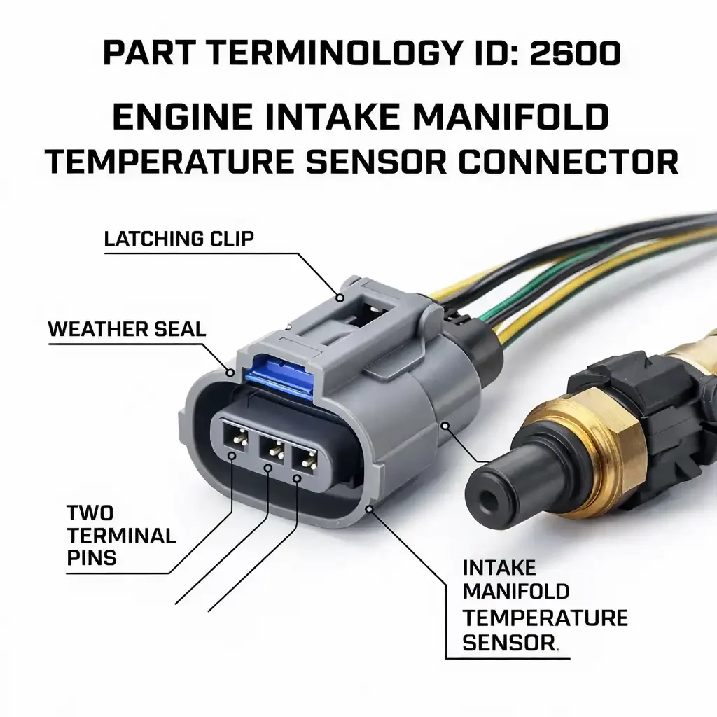
Engine Intake Manifold Temperature Sensor Connector (PartTerminologyID 2600):Sensor Types, Connector Variants, and the Catalog Fields That Prevent Misshipments
The Engine Intake Manifold Temperature Sensor Connector is the kind of part that gets ordered fast and returned at a rate that surprises sellers who treat it as a generic two-terminal pigtail. It is not generic. The sensor it serves mounts directly in the intake manifold body in a high-thermal-stress location, and the connector varies in terminal count, housing geometry, and sealing specification across applications in ways that fitment data alone does not capture.
The return pattern is consistent: buyer orders by vehicle, receives a connector with the correct terminal count, discovers the housing profile does not match the sensor body or the mounting location is wrong for their sensor type. The listing said correct fitment. The catalog never described what it was selling with enough specificity to prevent the mismatch.
This guide covers PartTerminologyID 2600 in full: what the sensor does, where the variant complexity comes from, what catalog fields prevent returns, and what listing language lets buyers verify compatibility before they order.
PCdb Status for PartTerminologyID 2600
PartTerminologyID
◦ 2600 in both current PIES 7.2 / PCdb and future PIES 8.0 / PCdb 2.0. No change on migration.
Terminology Name
◦ Engine Intake Manifold Temperature Sensor Connector. No rename in PIES 8.0.
Category
◦ Engine
SubCategory
◦ Fuel Delivery
Status
◦ Active in both schema versions.
The full terminology name is important: it separates this connector from the intake air temperature sensor connector, which mounts in the air intake tract rather than the manifold body, and from coolant temperature sensor connectors, which serve a different location entirely. These three connectors are frequently confused in buyer searches and sometimes in catalog data. The PartTerminologyID distinction is correct. Maintaining it in the catalog is the seller's job.
What the Sensor Does and Why Location Matters
The intake manifold temperature sensor is a thermistor mounted in the manifold body that reads the temperature of the air charge inside the manifold after the throttle body. The ECM uses this signal to adjust fuel injection timing, ignition timing, and in some cases idle speed control based on the thermal state of the intake charge.
The distinction between manifold-mounted and air-stream-mounted sensors is the most important cataloging boundary in this category. The air-stream IAT sensor mounts in the intake tube or air filter housing and reads ambient air temperature before the throttle body. On some engines both sensors are present. The connectors for the two sensor types often look similar at the terminal face because both serve two-terminal thermistor elements, but the housing geometry is specific to the sensor body profile at each mounting location. A manifold-mounted connector housing will not correctly mate with an air-stream sensor head, and vice versa, even when terminal count matches.
When the manifold temperature sensor connector fails, the ECM loses the intake charge temperature signal. Typical symptoms are enriched fuel delivery in warm conditions, retarded timing, and a stored diagnostic code for the sensor circuit. The vehicle usually remains drivable, which means the buyer has time to receive a wrong part, attempt installation, and wait for the correct one. Every step of that delay traces to the listing.
Why This Category Generates Returns
Manifold Generation Changes Split Connector Designs
The manifold temperature sensor mounts in the manifold casting, so its connector design tracks with manifold design changes rather than with model year or engine displacement alone. When a manufacturer revised the intake manifold, the sensor bung geometry often changed, which changed the sensor body profile and the connector housing required to mate with it. A single fitment row covering a model run that spanned a manifold revision will deliver the wrong connector to buyers on the wrong side of that revision. Fitment data captures year, make, model, and engine. It does not capture manifold generation.
Manifold and Air-Stream Connectors Appear in the Same Search Results
Some aftermarket catalog systems surface PartTerminologyID 2600 and the air-stream IAT connector under the same vehicle search because both serve intake temperature measurement. The housing profiles are sometimes similar enough that a face-on product photograph does not reveal the incompatibility. A buyer who needed a manifold-mounted connector and received an air-stream connector finds the housing does not seat against the manifold sensor bung. The fix at the catalog level is one word in the title: manifold-mounted. It costs nothing. It prevents this return on every order.
Two-Terminal and Three-Terminal Variants Co-Exist on the Same Platforms
The standard manifold temperature sensor circuit requires two connections: a reference voltage from the ECM and a signal return. This produces a two-terminal connector on most applications. Some sensor designs add a dedicated ground terminal, producing a three-terminal connector that is physically incompatible with two-terminal designs. On platforms where the sensor changed from two-terminal to three-terminal during the production run, both variants list to the same vehicle. Without terminal count in the listing, the buyer has no way to verify which variant they need.
RETURN PREVENTION IN FOUR FIELDS
The majority of returns on PartTerminologyID 2600 trace to four missing data points: mounting location not stated, terminal count absent, housing shape not described, and standalone versus combined sensor type not noted. Adding these four fields to every listing eliminates the structural causes of misshipment in this category.
The Complete Variant Universe for PartTerminologyID 2600
1. Terminal Count
• 2-terminal. The most common configuration. Serves the reference voltage input and signal return for a standard thermistor sensor. Appears across most domestic and import applications.
• 3-terminal. Adds a dedicated ground terminal. Present on applications where the ECM requires an isolated sensor ground to prevent ground offset errors. Physically incompatible with two-terminal sensor designs even when housing shape is similar.
Terminal count must appear in the listing title and item specifics. On platforms where both variants were used across the production run, a listing without terminal count data will produce a wrong-count shipment on a predictable share of orders.
2. Connector Body Shape
The connector housing must match the profile of the sensor head at the mating point. The manifold surface around the sensor bung constrains the housing geometry, and a connector with the wrong body profile will not seat or latch correctly even with the right terminal count.
• Compact rectangular housing. The most common profile for domestic two-terminal applications. Common on GM, Ford, and Chrysler applications from the 1990s through the 2000s.
• Oval or rounded housing. Appears on Toyota, Honda, and Nissan applications. The oval profile is a hard differentiator from domestic rectangular housings with the same terminal count. Must be noted in the title on import application listings.
• Square housing. Present on some applications where the sensor head profile requires a more square connector body. Less common but found on specific European and import platforms.
Housing shape must be described in words alongside product photographs. A face-on image shows terminal layout but does not communicate the profile that determines whether the connector clears the manifold surface around the sensor bung.
3. Wire Entry Angle
• Straight entry. Wire bundle exits in line with the connector axis. Used where the harness routes away from the manifold surface along the direct approach path.
• 90-degree entry. Wire bundle exits perpendicular to the mating face. Used where the harness must route along the manifold surface or around an adjacent component immediately after the connector.
A wrong wire entry angle creates harness stress at the connector body in a location already subject to heat cycling from the manifold. This accelerates housing fatigue and produces a premature connector failure. Wire entry angle belongs in the item specifics on every listing.
4. Seal Type and Thermal Rating
• Single wire seal per terminal. Standard on most modern applications. Prevents moisture and oil vapor migration into the connector from the harness side.
• Peripheral face seal. Seals the connector mating face against the sensor body. Present on some applications in addition to wire seals.
• Unsealed. Present on some older or lower-exposure applications. Note explicitly and recommend sealed replacement where available for the application.
The manifold surface generates radiant heat and oil vapor. A non-sealed replacement on a sealed application allows contamination to wick into the connector body at the terminal cavities, accelerating corrosion in an already thermally stressed location. Seal specification should match or exceed the original.
5. Pigtail Length and Wire Gauge
• Pigtail length. State in inches. Manifold sensor pigtails are typically short, commonly 6 to 10 inches, because the sensor is within reach of a nearby harness branch. Even a two-inch difference in pigtail length can determine whether the repair is possible without harness extension.
• Wire gauge. Typically, 20 or 22 AWG for manifold temperature sensor circuits. Both wires carry logic-level signals only. Stating the gauge allows professional buyers to verify circuit compatibility with the original harness.
• Wire colors. Note when colors match OE convention. Technicians splicing into the harness on a partially disassembled engine use wire color as a quick verification step.
6. Standalone vs. Combined Sensor Type
Some GM and import applications use a combined MAP and IAT sensor that integrates manifold absolute pressure measurement and intake temperature measurement in one sensor body. The connector for a combined sensor carries both the pressure sensing circuit and the temperature sensing circuit, requiring four or more terminals. This connector is a completely different product from the two-terminal standalone temperature sensor connector, even though both mount on the intake manifold. These two connector types must never share a listing.
Platform Notes for High-Volume Applications
GM V6 and V8 Applications
GM applications on the 3.1, 3.4, 3.8, and related V6 families from the 1990s and early 2000s use a two-terminal Delphi or Packard compact rectangular connector for the manifold temperature sensor. Some GM engine families went through manifold revisions that changed the sensor bung geometry mid-generation. Application data should note the manifold generation or sensor part number range when a revision occurred. GM applications using a combined MAP/IAT sensor require a separate four-terminal listing and must not be grouped with standalone temperature sensor connector listings even when vehicle fitment overlaps.
Ford EFI Applications
Ford EFI applications use a two-terminal connector for the manifold charge temperature sensor across most domestic V6 and V8 applications. The Ford connector family uses a housing profile and latch design that differs from GM Delphi connectors even at matching terminal counts. The Ford manifold temperature sensor, sometimes listed under the Ford-specific name Charge Temperature Sensor, is mounted at varying positions on the intake manifold depending on engine generation. The mounting position affects the pigtail length needed to reach the nearest harness branch, and that length varies enough across engine generations that it should be noted in the application data for Ford listings.
Toyota and Honda Import Applications
Toyota applications on the 2AZ, 1GR, 2GR, and related families use a two-terminal Sumitomo or Toyota-proprietary connector with an oval or rounded rectangular housing. Honda applications on K-series and J-series engines use a similar oval or compact rounded profile from the Sumitomo family. Both require the oval housing noted explicitly in the title because domestic rectangular connectors with matching terminal counts appear in the same search results for these applications and will not fit the import sensor head.
European Applications
BMW, Mercedes-Benz, and Volkswagen Group applications use manifold temperature sensor connectors from Bosch or TE Connectivity families with housing profiles specific to those connector families. Some integrated sensor designs on European engines combine temperature and pressure sensing in one body, requiring three or four terminals. Listings for European applications must confirm whether the sensor is standalone or combined, and must note the connector family to prevent buyers from substituting domestic or Japanese connector families based on terminal count alone.
Catalog Fields That Reduce Returns for PartTerminologyID 2600
Core Identification Fields
Sensor Mounting Location
◦ Manifold-mounted. Required in the title or first bullet on every listing. Primary separator from air-stream IAT connectors.
Terminal Count
◦ 2-terminal or 3-terminal. Required in the title and item specifics.
Connector Body Shape
◦ Compact rectangular, Oval or rounded, or Square. Written description required. Import applications with oval housings require the shape in the title.
Wire Entry Angle
◦ Straight or 90-degree. Required.
OEM Connector Family
◦ Delphi, Packard, Sumitomo, Bosch, TE Connectivity, or other. Required on import and European applications.
Sealing, Wire, and Sensor Type Fields
Seal Type
◦ Wire seals, Peripheral face seal, Both, or Unsealed.
Secondary Lock
◦ Push-tab, Slide lock, or None.
Pigtail Length
◦ State in inches.
Wire Gauge
◦ State in AWG. Typically, 20 or 22 AWG.
Sensor Type
◦ Standalone temperature sensor or Combined MAP/IAT sensor. Required on any application that used both. These connectors are not interchangeable.
Manifold Generation Note
◦ Required when the manifold or sensor design changed during the production run. Use production date or sensor part number range as the differentiator.
Sensor Compatibility Statement
◦ One sentence naming the sensor design this connector fits and what it does not fit.
The Most Common Listing Mistakes for PartTerminologyID 2600
Mistake 1: Mounting Location Not Stated
The single most preventable return in this category. A listing without manifold-mounted will be ordered by buyers who needed an air-stream IAT connector, and bypassed by buyers searching specifically for manifold connectors. One word in the title fixes this on every listing.
Mistake 2: Terminal Count Not Stated
Two-terminal and three-terminal variants co-exist on overlapping applications. A listing without terminal count sends the wrong variant to buyers on platforms that used both designs. Terminal count belongs in the title.
Mistake 3: Oval Housing Not Called Out on Import Applications
Toyota and Honda applications require oval-housing connectors. Domestic rectangular connectors with matching terminal counts appear in the same search results. Without the oval housing noted in the title, buyers order the wrong housing profile. The connector will not seat against the import sensor head.
Mistake 4: Combined MAP/IAT Connector Listed as Standalone Temperature Sensor Connector
The combined MAP/IAT sensor uses a four-terminal connector carrying both pressure and temperature circuits. It is not the same product as the two-terminal standalone temperature sensor connector. These must be separate listings. Grouping them produces wrong-terminal-count shipments on every combined sensor application.
Mistake 5: Manifold Generation Change Not Noted
A mid-generation manifold revision that changed the sensor bung creates a compatibility break that fitment data does not capture. Note the production date or sensor part number break in the application data wherever the supplier data supports it.
Mistake 6: Pigtail Length Not Specified
Manifold sensor pigtails are short. A two-inch shortfall can make the repair impossible without harness extension in a confined manifold location. State the length in inches on every listing.
Marketplace-Ready Listing Standards for PartTerminologyID 2600
Required Title Elements
Domestic two-terminal rectangular application:
Intake Manifold Temp Sensor Connector, Manifold-Mounted, 2-Terminal, Rectangular Housing
Toyota oval-housing application:
Intake Manifold Temp Sensor Connector, Manifold-Mounted, 2-Terminal, Oval Housing, Fits Toyota
Combined MAP/IAT application:
Intake Manifold MAP/IAT Sensor Connector, Manifold-Mounted, 4-Terminal, Fits GM Combined Sensor
Required Bullet Points
• MOUNTING LOCATION: Manifold-mounted. Required on every listing.
• TERMINALS: 2-terminal or 3-terminal. State exact count.
• HOUSING SHAPE: Rectangular, Oval, or Square. Written description required.
• WIRE ENTRY: Straight or 90-degree.
• SEAL TYPE: Wire seals, Face seal, Both, or Unsealed.
• PIGTAIL LENGTH: State in inches.
• WIRE GAUGE: State in AWG.
• SENSOR TYPE: Standalone temperature sensor or Combined MAP/IAT. Required when the application used both.
• COMPATIBILITY NOTE: One sentence. Sensor design this connector fits and what it does not fit.
Compatibility Statement Templates
TEMPLATE A: STANDALONE TEMPERATURE SENSOR
Fits: Standalone 2-terminal intake manifold temperature sensor. Manifold-mounted. Does not fit: combined MAP/IAT sensor applications (4-terminal) or air-stream IAT connectors. Verify sensor is standalone temperature sensor before ordering.
TEMPLATE B: IMPORT OVAL HOUSING
Fits: Toyota 2-terminal manifold temperature sensor with oval connector housing. Manifold-mounted. Does not fit: domestic rectangular-housing connectors with same terminal count. Oval housing profile is required for correct fitment on this application.
TEMPLATE C: COMBINED MAP/IAT SENSOR
Fits: GM combined MAP and IAT sensor in single manifold-mounted body. 4-terminal connector. Does not fit: standalone 2-terminal temperature sensor connectors. Verify sensor is the combined MAP/IAT design before ordering.
FAQ for Engine Intake Manifold Temperature Sensor Connector (PartTerminologyID 2600)
What is the difference between a manifold temperature sensor connector and an IAT sensor connector?
The manifold temperature sensor mounts in the intake manifold body and reads charge air temperature inside the manifold after the throttle body. The IAT sensor mounts in the intake tube or air filter housing and reads ambient air temperature before the throttle. Both use two-terminal thermistor connectors that can look similar at the terminal face, but the housing geometry is specific to the sensor body profile at each mounting location. The two connectors are not interchangeable. The listing must state manifold-mounted to separate them.
My connector has the right terminal count but will not mate with the sensor. What is wrong?
The most common cause is a housing profile mismatch. Connectors with identical terminal counts can have different housing depths or body shapes that prevent correct engagement with the sensor head. This is most common when ordering domestic rectangular connectors for import oval-housing applications, or when ordering across a manifold generation change where the sensor bung geometry changed. Compare the housing profile of your original connector to the replacement before attempting forced installation.
My vehicle has a combined MAP and IAT sensor. Which connector do I need?
A combined MAP/IAT sensor integrates manifold pressure measurement and temperature measurement in one body. The connector for this sensor carries both circuits and requires four or more terminals. It is a different product from the two-terminal standalone temperature sensor connector. Verify the listing specifies combined MAP/IAT compatibility and confirms the four-terminal count before ordering.
Does seal type matter on a sensor connector this small?
Yes. The intake manifold surface generates radiant heat, and oil vapor from the crankcase breather contacts the manifold area. An unsealed connector on a sealed application allows moisture and oil vapor to wick into the terminal cavities, accelerating corrosion in a location already under thermal stress. Use a connector that matches or exceeds the sealing specification of the original.
Catalog Quality Checklist for PartTerminologyID 2600
1. State manifold-mounted in the title or first bullet. Required on every listing. Primary separator from air-stream IAT connectors.
2. State terminal count in the title and item specifics. 2-terminal or 3-terminal.
3. Describe housing shape in words. Import applications with oval housings require the shape in the title.
4. Note wire entry angle. Straight or 90-degree.
5. Specify seal type.
6. Specify pigtail length in inches.
7. State wire gauge in AWG.
8. Identify sensor type. Standalone temperature sensor or combined MAP/IAT. Must be separate listings.
9. Write a sensor compatibility statement. Name the sensor this connector fits. State what it does not fit.
10. Check for manifold generation changes. Split the fitment row if the sensor design changed mid-production.
11. Verify connector family for import and European applications. Prevents domestic connector substitution.
Final Thoughts
The intake manifold temperature sensor connector is a compact part with a concentrated set of catalog problems. Mounting location, terminal count, housing shape, and standalone versus combined sensor type are the four fields that drive the majority of returns in this category. Each one is an observable fact about the connector that can be captured once and applied to every listing and every order from that SKU forward.
The buyer searching for this part has a diagnostic code and a running vehicle. They have already identified the sensor location, pulled the damaged connector, and are ready to order. They need confirmation that the connector they are looking at is the right one. Four fields, mounting location, terminal count, housing shape, and sensor type, answer that question. One sentence of compatibility language closes it. That is the entire investment required to move from a return to a completed repair.