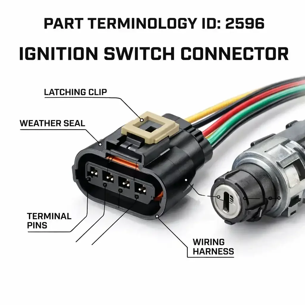
Ignition Switch Connector (PartTerminologyID 2596):Every Circuit Type, Terminal Configuration, and Catalog Field That Prevents Returns
The ignition switch connector sits behind the steering column and handles the most consequential electrical routing on the vehicle. Every circuit that changes state with key position, starter, accessory, run, ignition, and on modern vehicles security and column module circuits, passes through or originates at the ignition switch. The connector that serves it carries all of those circuits simultaneously in a single housing.
When this connector fails, the customer is working against a disabled vehicle. They search by year, make, and model, find a connector that lists to their application, order it, and discover at installation that the terminal count is wrong for their equipment level, or that the security circuit they needed is absent, or that a split-connector application shipped only one of the two housings required. The return is not a product failure. It is a catalog failure.
This guide covers PartTerminologyID 2596 in full: what circuits the ignition switch connector carries, why the variant range is wider than it appears, what catalog fields prevent returns, and what listing language gives buyers enough information to order correctly the first time.
PCdb Status for PartTerminologyID 2596
PartTerminologyID
◦ 2596 in both current PIES 7.2 / PCdb and future PIES 8.0 / PCdb 2.0. No change on migration.
Terminology Name
◦ Ignition Switch Connector. No rename in PIES 8.0.
Category
◦ Engine
SubCategory
◦ Ignition
Status
◦ Active in both schema versions.
The placement under Engine / Ignition is technically correct but narrower than the actual circuit scope of the part. The ignition switch connector also serves accessory, starter, security, and column module circuits. Sellers who treat this as an ignition-only connector and omit those additional circuit fields build listings that cannot support accurate buyer verification on vehicles where those circuits are the differentiating factor between connector variants.
What the Ignition Switch Connector Carries
The ignition switch is a multi-position rotary switch that routes battery power to different circuits depending on key position. The connector at the back of the switch body carries all of those circuit wires simultaneously. Terminal count on this connector is therefore determined by the number of distinct circuits the switch manages, not by the complexity of any single circuit.
The Core Circuit Set
Every ignition switch connector carries some version of these fundamental circuits regardless of vehicle or era:
• Battery feed. A constant power input from the battery, present at the connector regardless of key position. Typically the highest-amperage terminal in the connector.
• Accessory circuit. Powers radio, windows, and other accessories in the accessory position, and on some vehicles also in the run position.
• Run circuit. Powers the ignition system, fuel pump relay, ECM, and other run-essential components in both run and start positions.
• Start circuit. A momentary low-current output that closes the starter relay when the key is turned to start. Low current because it drives a relay coil, not the starter motor directly.
• Ground. Present on some connector designs as a dedicated terminal, absent on others where the switch grounds through the column housing.
These five circuits define the minimum terminal count for any ignition switch connector. Most connectors carry five to seven terminals to serve the core set with dedicated paths for each output.
Additional Circuits That Expand Terminal Count
Modern vehicle architecture adds circuits to the ignition switch connector that did not exist on older platforms. Each addition increases terminal count and creates a connector that is physically incompatible with lower-count versions for the same vehicle.
• Second accessory circuit. Some vehicles split accessories into two timed groups with different position or delay characteristics. This requires a second dedicated accessory output terminal.
• Second run circuit. Some applications use a separate run circuit for specific loads such as heated rear window or secondary HVAC, on a separate fused path from the main run output.
• Security or immobilizer circuit. Vehicles with factory transponder immobilizer systems added a circuit to the ignition switch connector that carries the immobilizer signal or a reference voltage for the transponder ring. This circuit is absent from pre-security versions of the same platform and its absence from the replacement connector is a hard compatibility break that produces a no-start condition after installation.
• Steering column module circuit. Vehicles with column-mounted controls for cruise, audio, or phone often route column module power through the ignition switch connector because the module power state tracks with key position.
• Illumination circuit. Some ignition switch assemblies include position indicator illumination, adding a lighting supply terminal to the connector.
The practical result of these additions is that ignition switch connectors for a given platform can exist in configurations spanning four or more terminals depending on model year and equipment level. A base-trim connector and a fully-equipped connector for the same vehicle both mount to the same switch body location. Neither substitutes for the other.
THE TERMINAL COUNT EXPANSION PROBLEM
The most common ignition switch connector return: a buyer orders by vehicle fitment and receives a connector with the correct mounting geometry but fewer terminals than their switch requires. The missing terminals serve the immobilizer or column module circuits their vehicle has. The listing grouped base-trim and fully-equipped fitments under one entry without noting the terminal count difference. The fix is two listings, not one listing with a disclaimer.
What PartTerminologyID 2596 Does Not Cover
Buyers sourcing ignition switch connectors sometimes confuse this part with adjacent components in the column assembly. The listing must be clear about what it serves and what it does not.
Ignition Lock Cylinder Connector
The ignition lock cylinder is the mechanical component the key inserts into. On many vehicles it is a separate assembly from the electrical ignition switch body behind it. When the lock cylinder has its own electrical connector, that connector typically carries only the transponder or key-in-switch detection circuit, two or three terminals at most. It is not the same part as the ignition switch connector, which carries the full power routing circuit. On some vehicles both connectors are required during a repair. A listing for PartTerminologyID 2596 must confirm it serves the ignition switch electrical body, not the lock cylinder.
Clockspring and Column Harness Connectors
The steering column contains multiple connectors beyond the ignition switch connector: the clockspring or spiral cable assembly, the turn signal and multifunction switch, and on modern vehicles column-mounted paddle shifters or drive mode selectors. These column connectors are sometimes purchased during the same repair and occasionally share connector family designs with the ignition switch connector. A buyer who receives the wrong column connector from an ambiguous listing discovers the error only at installation. One sentence in the listing description confirming circuit function and mounting point prevents this.
Push-Button Start Module Connectors
Push-button start systems do not have a traditional rotary ignition switch. The push-button module communicates a button state to the BCM via a network signal. Power routing functions traditionally performed by key position are handled by the BCM or PCM. Some catalog systems apply the ignition switch connector label to the push-button module connector because both serve an ignition-adjacent function. They are electrically and physically different parts. If both are cataloged under PartTerminologyID 2596, the listing title must make the switch type explicit to prevent cross-ordering.
The Complete Variant Universe for PartTerminologyID 2596
1. Terminal Count
Terminal count on ignition switch connectors ranges from four terminals on simple older applications to twelve or more on modern fully-equipped vehicles. Unlike connector categories where two or three counts cover the majority of the market, ignition switch connector terminal counts are distributed across a wider range because each equipment addition contributes one or two terminals to a connector that may already carry six or eight.
• 4 to 5 terminal. Older applications with basic accessory, run, start, and battery circuits. Common on domestic applications from the 1970s through the mid-1980s.
• 6 to 7 terminal. Mid-era applications with dedicated ground, separate accessory and run circuits, and start circuit. Common on domestic and import applications from the mid-1980s through the mid-1990s.
• 8 to 9 terminal. Applications with immobilizer, second accessory, or column module circuits added to the core set. Common on mid-1990s through mid-2000s security-equipped vehicles.
• 10 to 12 terminal. Fully-equipped modern applications with immobilizer, column controls, illumination, and multiple accessory and run circuits.
Terminal count must appear in the title and item specifics on every listing. The count range within a single vehicle platform can span four or more terminals across trim levels, and fitment data alone will not separate them.
2. Connector Body Configuration
The connector body must align with the switch body mounting point, mate in the correct orientation, and lock in a position that resists backing out under normal column operation.
• Single rectangular housing with position key. A physical tab on the housing aligns with a notch on the switch body, allowing installation in one orientation only. Absence of the position key on a replacement is a safety concern: reversed installation routes power to the wrong circuits.
• Single rectangular housing without position key. Used on applications where the terminal layout itself prevents reversed installation. Less common on modern applications.
• Dual housing or split connector. Some applications route ignition switch circuits through two separate connector bodies. Both are required for a complete repair. A listing that shows only one housing without noting the second is an incomplete product for that application.
• Rotating or radial connector. Some column designs use a connector that mates from the side of the switch body with a rotating retention mechanism. Not interchangeable with rear-entry rectangular housings regardless of terminal count.
• Weatherproof housing with integral seal. Common on truck and SUV applications where the column has more exposure. Includes a peripheral face seal and individual wire seals. A non-sealed replacement on a sealed application allows moisture intrusion into the switch body.
3. Wire Entry Angle
The ignition switch sits in a constrained space behind the column. The wire bundle must exit the connector and route down or along the column without stress at the connector body. Wire entry angle errors on ignition switch connectors produce a specific and serious problem: a tilt or telescoping column changes the stress angle on the harness during adjustment. Over time, a wrong-angle connector can crack the housing or cause terminal movement inside the housing.
• Straight entry. Wire bundle exits in line with the connector axis. Used where the harness runs directly away from the switch toward the dash or floor.
• 90-degree entry. Wire bundle exits perpendicular to the mating face. Used where the harness routes along the column rather than away from the switch face.
4. Pigtail Length
Ignition switch connector pigtails are typically longer than other engine electrical pigtails because the harness must reach from the switch location in the column down to the junction block or fuse panel under the dash. State length in inches on every listing. A column repair with limited access does not accommodate discovering a short pigtail after the column shroud is reinstalled.
• Short, 6 to 8 inches. Appropriate where the splice point is within the column shroud or immediately adjacent to the switch.
• Standard, 10 to 14 inches. The most common aftermarket offering for most domestic applications.
• Long, 16 inches and above. Required when harness damage extends further down the column, or when column mounting position requires longer routing to reach the main harness.
5. Wire Gauge by Circuit Group
The ignition switch connector carries circuits with very different current requirements in the same housing. The battery feed terminal and the accessory or run output terminals carry the full load of the circuits they supply, which can be 20 to 30 amperes or more. The start circuit drives only a relay coil. Security and signal circuits carry logic-level current only. Undersized wire gauge on a high-current circuit creates a genuine safety risk, not just a performance issue.
• Battery feed and high-current output circuits. Typically 12 or 14 AWG on domestic applications.
• Accessory and run circuit wires. Typically 14 or 16 AWG depending on load.
• Start circuit wire. Typically 18 or 20 AWG. Low current, relay-drive only.
• Security, immobilizer, and signal circuit wires. Typically 20 or 22 AWG. Logic-level signals only.
Wire gauge must be stated per circuit group. It is required information for professional buyers verifying circuit integrity on a safety-critical connector.
Security System and Immobilizer Integration
The interaction between the ignition switch connector and the vehicle security system is the most frequently underrepresented dimension of this part in aftermarket catalog data, and the one with the most serious consequence when it is wrong.
How the Immobilizer Circuit Routes Through the Connector
Factory transponder immobilizer systems use a transponder ring in the column to read the chip embedded in the key head. The ECM allows the engine to start only if the transponder signal matches the programmed value. On applications where this signal routes through the ignition switch connector, the connector must include the terminal for this circuit. A connector without this terminal will allow power routing to function correctly, but will interrupt the transponder reader path, producing a no-start condition that presents as a security system fault rather than a connector fitment error.
This is the return that generates the most frustrated buyers in this category. The connector installs without mechanical resistance. The switch position routing works. The vehicle will not start. The buyer calls the fault a defective part. The part is not defective. The listing failed to separate security-equipped and base-trim fitments.
The Correct Catalog Approach for Security System Splits
The correct approach for any platform produced with and without factory security is to create two separate listings: one for the base connector without security terminals, and one for the security-equipped connector with the additional terminals. The terminal count difference is the differentiator in the title. A plain-language note in the item specifics states which security system the higher-count connector serves.
Do not write verify security system equipment as a disclaimer on a single combined listing. That instruction does not tell the buyer what they are looking for or what the terminal count difference is. Two listings with explicit counts is the only catalog approach that actually prevents these returns.
SECURITY SYSTEM FITMENT NOTE
If your vehicle has a factory transponder immobilizer, Passlock, PATS, or Sentry Key system, your ignition switch connector includes terminals for those circuits that are absent from the base connector for the same platform. Ordering the base connector on a security-equipped vehicle installs without obvious error, then produces a no-start or security fault. Count the terminals on your original connector and verify against the listing before ordering.
Platform Notes for High-Volume Applications
GM Full-Size Trucks and SUVs
GM C/K and Silverado/Sierra platforms from the late 1980s through the early 2000s span multiple ignition switch connector generations. The GMT400 generation uses a different switch body and connector than the GMT800 generation. Within GMT400, the connector changed when GM added the VATS security system, and changed again when Passlock replaced VATS. Each of these three connector generations has a different terminal count and housing geometry. A single fitment row covering the full production span will generate returns on every order that falls on the wrong side of either design break. The GM full-size truck ignition switch connector requires at minimum three distinct catalog entries across this span, each with a clear production range and security system note.
Ford F-Series and Explorer
Ford full-size truck and Explorer applications across the OBS and OBD2 generations have distinct ignition switch connector designs. The introduction of the PATS transponder immobilizer in the mid-1990s added terminals to the connector. Ford applications before and after PATS require different connectors, and the introduction date varies by model and model year. The catalog must split at the PATS introduction for each specific Ford platform. An additional Ford-specific note: the retention tab design on Ford column-mounted switch connectors is specific to the Ford column assembly and will not transfer to GM or Chrysler column applications even when terminal count appears similar.
Chrysler LH and JA Platforms
Chrysler LH-platform vehicles including Dodge Intrepid and Chrysler Concorde used an ignition switch connector that changed when the Sentry Key immobilizer was introduced. The Sentry Key version adds terminals for the transponder communication circuit. Application data for LH-platform vehicles must split at the Sentry Key introduction date. Chrysler JA-platform vehicles including Dodge Stratus and Chrysler Cirrus have similar security system splits but use a different connector design from the LH platform. Do not group LH and JA connectors under one entry based on security system similarity alone.
Toyota Camry and Corolla
Toyota's ignition switch connector on Camry and Corolla applications changed with the introduction of the factory immobilizer on export-market vehicles in the mid-1990s. The connector family is Sumitomo or Yazaki with a housing profile that differs from domestic connector families of the same era. Application data must note both the connector family and the immobilizer equipment split to prevent the two most common return types on Toyota applications: buyers ordering domestic-family connectors for import-family applications, and buyers ordering pre-immobilizer connectors for immobilizer-equipped vehicles.
Honda Accord and Civic
Honda ignition switch connector applications follow a pattern similar to Toyota. The connector family is Sumitomo or Yazaki, the housing profile differs from domestic applications, and the immobilizer introduction in the mid-1990s added terminals that create a compatibility break. An additional Honda-specific note: some Honda ignition switch connectors integrate the ignition switch and the steering lock electrical circuit in one housing, which adds terminals for the steering lock circuit beyond the standard ignition circuit set. Listings for Honda applications where this integration applies must note the steering lock circuit and include it in the terminal count.
Catalog Fields That Reduce Returns for PartTerminologyID 2596
Core Identification Fields
Switch Type
◦ Column-mounted separate switch, Column-mounted integrated assembly, Dash-mounted switch, or Push-button start module connector. Required. This is the primary filter above terminal count.
Terminal Count
◦ Exact count. Required in the title and item specifics. For split-connector applications, state the count per housing.
Connector Body Configuration
◦ Single with position key, Single without position key, Dual housing (note both required), or Rotating radial. Required.
Wire Entry Angle
◦ Straight or 90-degree. Required.
OEM Connector Family
◦ Packard, Delphi, Sumitomo, Yazaki, Bosch, or other. Provides a verification reference for technical buyers ordering on import applications.
Circuit and Security Fields
Security System Fitment
◦ With factory security or immobilizer system, or Without factory security. Required on any platform produced with and without factory security. This is a hard compatibility split, not a disclaimer.
Immobilizer Circuit Present
◦ Yes or No. Note which terminal carries the transponder or immobilizer signal when present.
Circuit Content Note
◦ A brief statement listing what circuit types are in the connector. For example: 1 battery feed, 2 accessory, 1 run, 1 start, 1 immobilizer, 1 ground equals 7 terminals. This level of detail allows professional buyers to verify their specific application.
Wire and Pigtail Fields
Pigtail Length
◦ State in inches. Required. Column repairs have limited access and pigtail length is a go/no-go factor before the repair begins.
Wire Gauge by Circuit Group
◦ State AWG for high-current circuits (battery, accessory, run) separately from low-current circuits (start, security, signal). Required on a safety-critical connector.
Wire Count
◦ Confirm against terminal count. Note if any terminals share a circuit or if any wires carry multiple functions.
Application and Compatibility Fields
Mounting Location
◦ Column-mounted or Dash-mounted. Required on any non-column application.
Column Type Note
◦ Fixed, Tilt, or Telescoping. Note pigtail length and routing considerations for adjustable columns.
Split Connector Note
◦ When the application uses two connector housings, state this explicitly. Both connectors are required. Do not sell one without disclosing the second.
Generation or Production Note
◦ Required on any platform where the connector changed during the model run. State the production range this connector serves and the cause of the design change.
The Most Common Listing Mistakes for PartTerminologyID 2596
Mistake 1: Terminal Count Not Stated
A listing without a terminal count will be ordered by buyers across multiple equipment levels on the same platform. A six-terminal and an eight-terminal connector for the same vehicle both list to the same year, make, and model. They are not the same part. Terminal count belongs in the title on every ignition switch connector listing without exception.
Mistake 2: Security System Split Not Made
This produces the most consequential return in this category. The buyer installs the connector. The power routing functions work. The vehicle will not start because the immobilizer signal has no path. The return reason is listed as defective or wrong part. The part is neither. The listing failed to separate security-equipped and base-trim fitments. Two entries with explicit terminal counts and security system notes is the only fix.
Mistake 3: Dual-Connector Application Listed as Single Connector
Applications using two separate connector bodies at the ignition switch require both for a complete repair. A listing showing only one housing without noting the second sends the buyer into an incomplete installation. The listing must state that the application uses two connectors, list both, and confirm whether both are included or whether the second is sold separately. Ambiguity here generates an immediate return and a parts-ordering delay on a vehicle that is not running.
Mistake 4: Position Key Absent on Applications That Require It
The position key on an ignition switch connector prevents reversed installation, which on this part would route battery power to the wrong circuits. A replacement connector without the position key on an application that had one is a safety issue. Note position key presence in the item specifics. A buyer who receives a connector without the position key they expected will return it and should.
Mistake 5: Pigtail Length Not Specified
Ignition switch pigtails are longer than most other connector pigtails because the splice point is further from the connector. A technician who routes the column shroud back into position and then finds the pigtail short has to disassemble the column again. State the length in inches on every listing. Not a range. A measurement.
Mistake 6: GM Platform Generations Not Split
The GM full-size truck ignition switch connector changed at the VATS introduction, at the Passlock introduction, and at the GMT400 to GMT800 generation change. Three breaks, three distinct connectors. A single fitment row covering this entire span produces returns from buyers on each side of every one of those breaks. Three entries with clear production range notes is the correct catalog structure.
Mistake 7: Import Connector Family Not Identified
Toyota and Honda ignition switch connectors use Sumitomo or Yazaki connector families with housing profiles that differ from domestic connector families of the same era and terminal count. Omitting the connector family identifier allows buyers to order domestic-family connectors for import applications. The housing will not mate. The connector family name belongs in the item specifics on every import application listing.
Marketplace-Ready Listing Standards for PartTerminologyID 2596
Required Title Elements
A compliant title includes: part type as Ignition Switch Connector, the exact terminal count, the switch type when non-standard, and a security system or generation note when the application has a compatibility split.
GM GMT400 without security system:
Ignition Switch Connector, 6-Terminal, Column-Mount, Fits GM GMT400 Without Factory Security
Same platform with Passlock:
Ignition Switch Connector, 8-Terminal, Column-Mount, Fits GM GMT400 With Passlock Security System
Ford PATS-equipped application:
Ignition Switch Connector, 7-Terminal, Column-Mount, Fits Ford With PATS Transponder System
Required Bullet Points
• SWITCH TYPE: Column-mounted separate, Column-mounted integrated, Dash-mounted, or Push-button start module.
• TERMINALS: Exact count. Required.
• SECURITY SYSTEM: With factory security or immobilizer, or Without. Required on any platform with this split.
• CONNECTOR BODY: Single with position key, Dual housing (both required), or Rotating radial.
• WIRE ENTRY: Straight or 90-degree.
• PIGTAIL LENGTH: State in inches.
• WIRE GAUGE: High-current circuit gauge and low-current circuit gauge stated separately.
• CIRCUIT NOTE: What circuit types are in the connector. Battery feed count, accessory count, run, start, immobilizer if present.
• COMPATIBILITY: One sentence. What platform and generation this connector fits, and what it does not.
Compatibility Statement Templates
TEMPLATE A: SECURITY SYSTEM SPLIT
Fits: GM GMT400 full-size trucks and SUVs from 1992 through 1999 with Passlock security system. 8-terminal connector. Does not fit: base-trim GMT400 without factory security (6-terminal), or GMT800 generation (different switch body). Verify security system equipment and terminal count on original connector before ordering.
TEMPLATE B: FORD PATS SPLIT
Fits: Ford F-Series applications from 1996 through 2003 with PATS transponder immobilizer. 7-terminal connector. Does not fit: pre-1996 applications without PATS (different terminal count), or 2004 and later applications with revised switch body. Verify production year and PATS equipment.
TEMPLATE C: DUAL CONNECTOR APPLICATION
This application uses two separate connector housings at the ignition switch. Both connectors are included in this listing. Both must be installed for correct operation. Do not attempt installation with one connector only.
FAQ for Ignition Switch Connector (PartTerminologyID 2596)
Why does my vehicle not start after I installed the new ignition switch connector?
The most common cause is a missing immobilizer circuit. If your vehicle has a factory transponder immobilizer, Passlock, PATS, or Sentry Key system, the ignition switch connector must include terminals for those circuits. A connector without the immobilizer terminals allows power routing to function correctly but interrupts the security signal path, producing a no-start that presents as a security system fault rather than a connector issue. Count the terminals on your original connector and compare to the replacement. If the replacement has fewer, the missing ones are almost certainly the security circuit terminals.
My connector has the right terminal count but will not mate with the switch body. What is wrong?
The most likely cause is a connector body configuration mismatch. Two connectors with identical terminal counts can have different housing profiles, position key locations, or mating orientations that prevent correct engagement. This happens most often when ordering across platform generations where the switch body changed, or when a column-mount connector is ordered for a dash-mount application. Compare the housing profile and mating face geometry of your original connector against the replacement before attempting forced installation.
What is a position key on an ignition switch connector, and does it matter?
A position key is a physical tab on the connector housing that aligns with a notch on the switch body, allowing installation in only one orientation. On the ignition switch, reversed installation would route battery power to the wrong output circuits, causing immediate electrical problems. If your original connector had a position key, the replacement must also have one. A replacement without a position key on an application that requires one is a safety concern and a legitimate reason to return the part before installation.
My application uses two connectors at the ignition switch. Do I need both?
Yes. Applications that use two separate connector bodies route different circuit groups through each housing. One typically carries the primary power routing circuits and the other carries signal or security circuits. Replacing only one leaves the other circuit with original wiring that may also be damaged. Both connectors must be installed for correct operation. If the listing you ordered from included only one, contact the seller before proceeding with the repair.
How do I know if my vehicle has a factory security system that changes which connector I need?
The clearest indicator is the terminal count on your original connector compared to base-trim connector descriptions for your platform. If your connector has more terminals than the base-trim count, the extra terminals are the security circuit terminals. You can also check your vehicle's build sheet for a factory security or immobilizer option. For GM applications, the Passlock label on the ignition switch assembly confirms security system equipment. For Ford, the PATS label on the PCM or a transponder ring visible around the ignition cylinder confirms PATS. For Chrysler, the Sentry Key label on the key fob confirms immobilizer equipment.
Can I extend the pigtail if the one I receive is too short?
You can, but it adds a splice connection in a high-current circuit under the dash where access for future inspection is limited. A poor splice on the battery feed or accessory circuit wire creates a resistance point that generates heat under sustained load. The safer approach is to exchange the connector for one with the correct pigtail length before beginning the repair. If the pigtail received is genuinely too short, contact the seller for an exchange before proceeding.
Catalog Quality Checklist for PartTerminologyID 2596
Run this checklist before any ignition switch connector listing goes live. Each unanswered item is a gap that will produce returns.
1. Identify the switch type. Column-mounted separate, column-mounted integrated, dash-mounted, or push-button start module. Put it in the title.
2. State the exact terminal count in the title and item specifics. If the application has multiple counts by equipment level, create separate listings for each.
3. Check for security system split. If the platform was produced with and without factory security or immobilizer, create two separate listings. A disclaimer on a combined listing is not a substitute.
4. Describe the connector body configuration. Single with position key, dual housing, or rotating radial. Note whether position key is present.
5. Note wire entry angle. Straight or 90-degree.
6. Specify pigtail length in inches. An actual measurement, not a range.
7. State wire gauge for high-current and low-current circuit groups separately.
8. Write a circuit content note. List what circuit types are present: battery feed, accessory count, run, start, immobilizer if applicable.
9. Write a compatibility statement. Platform, generation, equipment level this connector serves. What it does not fit.
10. Check for dual-connector applications. If the switch uses two housings, note this. Confirm the listing includes both or states clearly that one is sold separately.
11. Check for generation splits on GM, Ford, and Chrysler applications. Split the fitment row at any design change and note the production range.
12. Verify mounting location. Note dash-mount on any non-column application.
Final Thoughts
The ignition switch connector is one of the few parts in the aftermarket where a catalog error can produce a safety or security consequence in addition to an installation inconvenience. A connector installed in the wrong orientation due to a missing position key, a connector that omits the immobilizer circuit terminal, or a connector with undersized wire gauge on a high-current circuit can each produce outcomes that go beyond a returned part.
The catalog fields required to prevent this are the same fields that reduce returns: switch type, terminal count, security system split, connector body configuration, position key presence, wire entry angle, pigtail length, wire gauge by circuit group, and a plain-language compatibility statement. These are observable facts. They require a one-time data effort per SKU and pay that effort back on every order that does not become a return or a safety callback.
The ignition switch connector buyer is not browsing. They have a disabled vehicle and they need to get the right part the first time. Give them the data to do that.