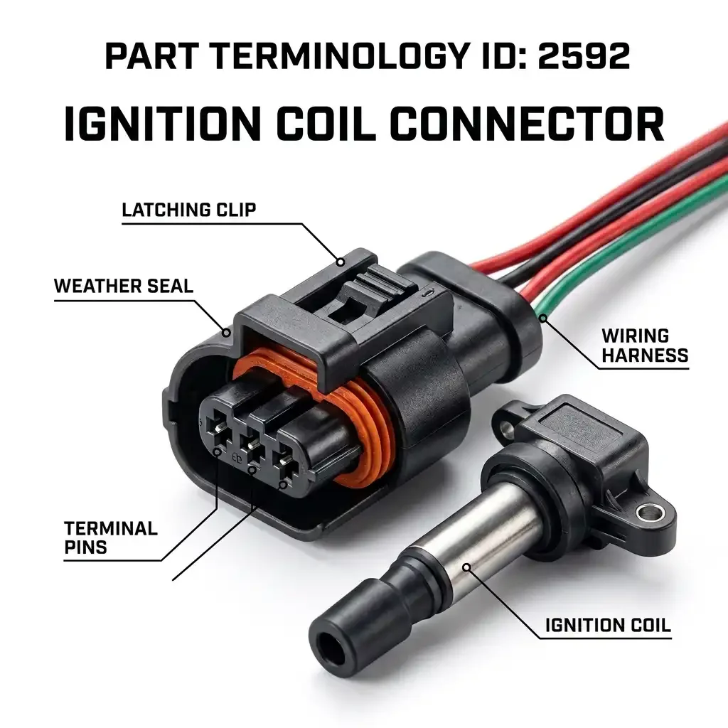
Ignition Coil Connector (PartTerminologyID 2592) Every Coil Design, Connector Variant, and Catalog Field That Prevents Misshipments
Ignition coil connectors are one of the highest-volume electrical connector categories in the aftermarket. Every cylinder on every fuel-injected engine with coil-on-plug, coil-near-plug, or coil-pack ignition has one, which means a six-cylinder engine has six of them and a V8 has eight. When a single connector fails and causes a misfire, the technician replaces it. When water intrusion damages a coil connector on one cylinder, the other connectors on the same engine are often in the same condition. Sales happen in multiples.
The volume is real. So is the return rate. Ignition coil connectors fail in one of the most electrically demanding environments on the engine, right next to the coil primary winding, which means heat, vibration, and high-voltage proximity are all working against the connector simultaneously. And because coil connector designs vary significantly across engine families, model years, and coil generations, a connector that matches the vehicle fitment in the catalog may still be wrong if the catalog data does not capture the coil design the connector actually serves.
This guide covers PartTerminologyID 2592 in full. It explains what drives the variance in this category, what catalog fields are required to prevent returns, and what listing language gives buyers enough information to order correctly the first time.
PCdb Status for PartTerminologyID 2592
Where this part sits in the current standards framework.
PartTerminologyID
◦ 2592 in both current PIES 7.2 / PCdb and future PIES 8.0 / PCdb 2.0. No change on migration.
Terminology Name
◦ Ignition Coil Connector. No rename in PIES 8.0.
Category
◦ Engine
SubCategory
◦ Ignition
Status
◦ Active in both schema versions.
The terminology name covers the connector that connects the engine wiring harness to the ignition coil primary circuit. As with other connector PartTerminologyIDs in the PCdb, the name identifies the circuit served but not the physical configuration. The configuration data must come from the catalog, and in this category the configuration variance is wide enough that a listing without it will misship a meaningful percentage of orders.
What the Ignition Coil Connector Serves: A Brief Ignition System Map
The ignition coil connector is not a single product. It is a family of products defined by the coil architecture it serves. To catalog this part correctly, the seller needs to understand the coil architectures that exist in the market, because each architecture produces a distinct connector requirement.
Distributor-Based Ignition with External Coil
Older distributor ignition systems use a single external coil that fires all cylinders through the distributor cap and rotor. The external coil typically uses a two or three terminal connector for the primary circuit: a switched power supply, an ECM control signal or points circuit, and in some designs a dedicated ground. These connectors are among the simplest in the category and appear on carbureted and early fuel-injected applications. Because the external coil serves all cylinders, only one connector is needed per engine, and the replacement connector is usually straightforward to identify once the coil part number is known.
The catalog challenge here is not variety. It is age. Many external coil applications are old enough that original connector design documentation is incomplete, and aftermarket connectors vary in housing profile and terminal type across suppliers. A listing that identifies the coil series by manufacturer and part number range, rather than just year make model, gives buyers the best chance of ordering correctly.
Coil Pack or Waste-Spark Ignition
Waste-spark ignition systems use a coil pack, which is a multi-coil module that fires pairs of cylinders simultaneously. A four-cylinder engine typically uses a two-coil pack, a V6 uses a three-coil pack, and a V8 uses a four-coil pack. The coil pack connector is a multi-terminal connector that serves all the coils in the module simultaneously, rather than individual connectors per coil.
Coil pack connectors are among the most complex in this category because the terminal count scales with the number of coils in the pack, and the housing must accommodate a large wire bundle entering from a single connector body. Terminal counts on coil pack connectors commonly range from six terminals on a four-cylinder two-coil pack up to twelve or more terminals on larger packs. The housing geometry is application-specific to the coil pack module design.
A critical catalog note for coil pack connectors: some applications use a single connector for the entire pack, and some use individual connectors per coil element within the pack. These are not the same product. A single-connector coil pack listing that should be an individual-coil connector listing will generate immediate returns from buyers who receive one large connector for a motor that uses four individual small connectors.
Coil-Near-Plug and Remote Coil
Coil-near-plug systems mount individual coils close to each spark plug but not directly on the plug. Each coil has its own connector, and the high-voltage output connects to the plug via a short spark plug wire. The connectors for these individual coils are typically two or three terminal designs for the primary circuit, similar in terminal count to external coil connectors but with different housing geometries suited to the mounting location close to the valve cover or cylinder head.
Some coil-near-plug connectors integrate a resistor or suppression component in the connector body itself. This is a variant that must be identified in the listing because a connector without the integrated resistor will not provide the same suppression function as the original even if the physical fitment is correct.
Coil-on-Plug Ignition
Coil-on-plug, or COP, systems mount an individual coil directly on each spark plug. Each coil has its own connector. This is the dominant ignition architecture on modern engines and generates the largest volume of ignition coil connector sales in the aftermarket.
COP coil connectors vary significantly in terminal count and housing design across manufacturers and engine generations. The three-terminal COP connector is the most common design, carrying switched power, ECM control signal, and ground. Some COP coils add a fourth terminal for an ignition confirmation signal or a diagnostic feedback circuit. Some add a fifth terminal for an integrated detonation sensor or a shared sensor circuit. Each additional terminal requires a distinct connector that is physically incompatible with lower-terminal-count versions even when the primary circuit terminals are identical.
COP connectors are also the most sensitive to housing geometry variance because the coil mounts directly on the spark plug in a confined bore, and the connector must mate with the coil body within that bore without interference from the valve cover or surrounding components. A connector with the correct terminal count but an incorrect latch orientation, body depth, or wire entry angle may physically fit onto the coil but will not latch correctly or will create harness stress that damages the connector over time.
Pencil Coil Designs
Pencil coils are a subset of coil-on-plug design where the coil body is long and narrow, designed to fit into a deep plug well in the cylinder head. The connector for a pencil coil typically fits around the top of the coil body and latches differently from the wider-body COP coils used on other applications. Connector geometry for pencil coils is application-specific and cannot be substituted with standard COP connectors even when the terminal count matches.
Pencil coil connector designs are especially common on European applications including BMW, Mercedes-Benz, Volkswagen Group, and Volvo. They also appear on some Ford and GM applications where deep plug wells require the pencil coil profile. The connector housing for these designs typically has a narrow, elongated profile and a specific latch design that aligns with the coil body orientation in the plug well. Listings for pencil coil connectors must identify the pencil coil design explicitly because the housing profile is the primary differentiator from standard COP connectors with the same terminal count.
ARCHITECTURE DETERMINES CONNECTOR DESIGN
The ignition system architecture is the first filter for coil connector compatibility. Distributor coil, coil pack, coil-near-plug, standard COP, and pencil coil connectors are not interchangeable even when terminal counts overlap. The catalog must identify the coil architecture in the listing. Year, make, model, and engine displacement alone do not capture coil architecture on platforms that changed ignition systems across a model run.
The Complete Variant Universe for PartTerminologyID 2592
With ignition system architecture established as the primary filter, the following attributes determine connector compatibility within each architecture type.
1. Terminal Count
Terminal count is the first numeric differentiator within an architecture type and must appear in every listing.
• 2-terminal. Appears on some distributor coil applications and on simple coil-near-plug designs where the ECM provides a switched ground signal and a separate power feed is not required.
• 3-terminal. The most common COP and coil-near-plug terminal count. Power, control signal, and ground. Appears across a very wide range of domestic and import applications.
• 4-terminal. Appears on COP coils with an ignition confirmation or ionization feedback signal, and on some coil pack applications. Also used on some coil-near-plug applications with an integrated suppression component that requires an additional circuit.
• 5-terminal. Appears on COP coils with integrated detonation sensing or shared sensor circuits, and on specific European applications where the coil connector carries additional diagnostic signals.
• 6-terminal and above. Coil pack connectors serving multiple coil elements simultaneously. Terminal count scales with the number of coil elements in the pack.
On COP applications in particular, three-terminal and four-terminal connectors appear on the same engine family across different model years or trim levels. A four-terminal connector will not mate with a three-terminal coil body and vice versa. Terminal count must appear in the title.
2. Connector Body Shape and Coil Body Interface
The connector housing must match the profile of the coil body at the mating point. Unlike some connector categories where shape is secondary to terminal layout, ignition coil connectors must fit within a specific spatial envelope defined by the coil body, the plug well depth, the valve cover clearance, and the harness routing path. A connector with the correct terminals but an incorrect body profile will not latch, will not seal, or will interfere with adjacent components.
• Standard COP housing. A compact rectangular or square housing with a primary latch on one face. The most common form factor for modern domestic COP applications. Many GM, Ford, and Chrysler COP connectors fall into this general family, though specific housing dimensions vary by coil generation.
• Pencil coil housing. Narrow, elongated housing designed to fit around the upper section of a pencil coil body in a deep plug well. The latch and wire entry are oriented to allow the wire bundle to exit the plug well without interference. These are not interchangeable with standard COP housings.
• Coil pack housing. Large multi-terminal housing with a single latch or locking mechanism serving the entire pack connector. Housing length scales with terminal count and wire bundle size.
• Top-hat or flanged housing. A housing with an external flange or collar that seats against the coil body upper surface. Common on some import COP applications and on coil-near-plug designs where the connector is also a retention element for the coil in its mounting bracket.
• Integral boot housing. Some COP connectors incorporate a rubber boot that seals the connector-to-coil interface against moisture and carbon tracking. The boot is part of the connector housing and its absence or mismatch creates a sealing failure at the coil connection point.
3. Wire Entry Angle
Wire entry angle on ignition coil connectors is more constrained than on most other engine connector applications because the coil is mounted in a fixed orientation on the engine and the harness routing is determined by valve cover geometry, cylinder head layout, and adjacent component clearance.
• Straight entry. Wire bundle exits in line with the connector body axis. Common where the harness runs perpendicular to the engine bank or away from the plug well.
• 90-degree entry. Wire bundle exits perpendicular to the mating face. Very common on COP applications where the harness must route along the valve cover surface rather than exiting vertically from the plug well.
• Angled entry variants. Some connector designs use 45-degree or other non-standard angles to accommodate specific valve cover or camshaft cover geometries. These are application-specific and must be noted in the listing.
Wire entry angle errors on ignition coil connectors produce a specific symptom: the connector seats and latches correctly at installation but the harness is under stress, and within a short period of operation the stress causes the connector to work loose, the terminal contact resistance increases, and a misfire code appears. The repair look correct at first inspection, but the vehicle comes back. Wire entry angle belongs in the item specifics on every COP connector listing.
4. Latch Type and Retention Design
Ignition coil connectors operate in a high-vibration environment next to a component that generates strong electromagnetic fields during operation. Latch design matters more in this location than in most other connector categories because a connector that backs out even partially will cause intermittent coil primary circuit interruptions that produce inconsistent misfire symptoms, the hardest kind of ignition fault to diagnose.
• Primary latch with push-tab release. A latch arm that snaps over a retention feature on the coil body, released by pressing the tab. The most common retention design on modern COP connectors.
• Squeeze-to-release latch. A latch that is released by squeezing the sides of the connector body. Used on some import COP applications where access to the top of the connector is limited in the plug well.
• Bayonet or twist-lock retention. Less common. Appears on some integrated boot designs where the connector is twisted to lock and unlock rather than using a latch arm.
• No latch, friction fit. Present on some older or lower-vibration applications. Must be noted because technicians will look for a latch during installation and may not seat the connector fully if they expect one.
• Wire retainer clip included. Some connectors include a separate wire retainer clip that holds the harness bundle against the coil body to reduce movement at the connector. Note whether included.
5. Seal Type and Environmental Protection
Ignition coil connectors are exposed to oil mist from valve cover gasket leaks, condensation from temperature cycling, and in some applications direct water splash. The seal specification of the replacement connector determines whether the repaired connection remains reliable over time.
• Single wire seals with face seal. Individual rubber seals on each wire plus a face seal around the connector body perimeter. The most complete sealing arrangement and the correct specification for most COP applications.
• Wire seals only. Individual seals per terminal cavity but no face seal. Adequate for most applications but may allow moisture migration along the connector body exterior in high-exposure locations.
• Integral boot seal. Where the connector housing incorporates a rubber boot that seals the entire connector-to-coil interface. Boot seals are critical on applications where the coil sits in a deep plug well that can accumulate water.
• Unsealed. Present on some older external coil and coil-near-plug applications. Note explicitly and recommend sealed replacement when available for the application.
Boot seal presence is a frequent source of returns on COP connector listings. A connector for a deep plug well application that does not include the boot will allow water to accumulate in the plug well and cause coil damage over time. The replacement connector must match the sealing specification of the original, not just the terminal layout.
6. Pigtail Length and Wire Gauge
Ignition coil connector pigtails carry primary ignition circuit current, which involves moderate current on the power supply wire and logic-level current on the ECM control wire. Wire gauge requirements vary by circuit.
• Pigtail length. State in inches. COP connector pigtails are typically shorter than other engine electrical pigtails because the coil is within reach of the main harness branch at each cylinder. Standard lengths are commonly 6 to 10 inches. Longer pigtails may be needed on engines where the harness routing has been modified or damaged further back from the coil.
• Wire gauge on power and ground circuits. Typically 16 or 18 AWG for the switched power and ground wires. The current through the coil primary circuit during charging is higher than for most signal circuits.
• Wire gauge on control signal circuit. Typically 20 or 22 AWG for the ECM control signal wire. Smaller gauge is appropriate for the logic-level signal.
• Wire count. Should match terminal count. On connectors with integrated suppression or feedback circuits, confirm that the pigtail wire count matches the terminal count rather than carrying only the primary circuit wires.
7. Integrated Components in the Connector Body
Some ignition coil connectors are more than a housing and terminals. The connector body may incorporate functional components that are part of the ignition circuit and must be present in the replacement for correct operation.
• Integrated resistor. Some coil-near-plug and early COP connector designs incorporate a resistor in the connector body to suppress radio frequency interference. If the original connector had an integrated resistor and the replacement does not, the vehicle may exhibit increased ignition noise on the radio or on-board electronics. Note resistor presence or absence explicitly.
• Integrated suppressor capacitor. Present on some connector designs, particularly on applications shared with sensitive electronics. Same note applies as for resistors.
• Connector-mounted retainer spring. Some designs use a spring in the connector body to maintain contact pressure on the coil primary terminals over the life of the connection. Not universal but present on some European applications.
Integrated components in the connector are the most commonly omitted detail in aftermarket connector listings and the one most likely to cause a functional complaint after installation. A connector that has the correct terminals and the correct housing but lacks the integrated resistor of the original will install without issue and cause a warranty comeback when the radio interference complaint surfaces.
OEM Coil Connector Families by Platform
Understanding which connector family a platform uses, and where design changes occurred, is the foundation of accurate catalog data for PartTerminologyID 2592. The following platform notes cover the highest-volume applications in the aftermarket.
GM LS and LT V8 Engines
GM LS-series V8 engines use a three-terminal COP connector that is among the highest-volume ignition coil connector applications in the aftermarket. The LS coil connector uses a rectangular housing with a 90-degree wire entry and a primary latch that pushes inward to release. The connector family used on early LS1 and LS6 applications differs slightly from the connector introduced on later LS2, LS3, and LS7 applications. The housing profile is similar but the latch geometry changed between generations. A listing that covers LS1 through LS9 with a single fitment row and no generation note will send the wrong connector to a portion of buyers.
The LS coil connector is also widely used in performance and engine swap applications beyond the original vehicle fitments. Listings for this connector see a disproportionate share of buyers doing swap builds rather than OE repairs. For these buyers, noting the coil part number compatibility in addition to vehicle fitment is useful catalog data.
GM EcoTec and Small Four-Cylinder Applications
GM four-cylinder applications using the EcoTec engine family use a three-terminal COP connector with a compact housing design that differs from the LS connector family. The EcoTec connector is smaller in housing cross-section and uses a different latch design. It is not interchangeable with LS connectors despite the same terminal count. Listings must identify the engine family, not just the terminal count, to prevent cross-ordering between GM V8 and four-cylinder applications.
Ford Modular V8 and EcoBoost Applications
Ford Modular V8 engines including the 4.6, 5.4, and 5.0 use COP connectors that changed across engine generations. The Two-valve, Three-valve, and Four-valve versions of the Modular engine used different coil designs, and the connectors changed accordingly. The Modular connector is not the same as the EcoBoost connector used on Ford four-cylinder and V6 turbocharged applications. Terminal count on Ford COP connectors is commonly three, but the housing geometry, latch design, and wire entry orientation differ across engine families. Listings must split by engine generation, not just by engine displacement.
A specific Ford catalog note: the Police Interceptor, F-150 Lightning, and SVT variants of Ford V8 engines sometimes used different coil and connector specifications from the standard production versions of the same engine. Fitment notes for performance and fleet applications of Ford engines should verify coil part number compatibility rather than relying solely on year and model.
Chrysler Hemi V8 Applications
Chrysler Hemi V8 engines from 2003 onward use a three-terminal COP connector with a housing profile specific to the Hemi coil body design. The Hemi connector is not interchangeable with earlier Chrysler V8 coil connectors or with the connector used on Chrysler four-cylinder and V6 applications. The latch on the Hemi COP connector uses a distinctive side-squeeze release rather than the push-tab release common on GM and Ford COP connectors. Listings for Hemi coil connectors must note the squeeze-release latch because technicians unfamiliar with the design will damage the connector attempting to release it using the push-tab method.
Toyota and Honda COP Applications
Toyota and Honda COP applications from the early 2000s onward use connector designs with housing profiles that differ from domestic COP connectors. Toyota applications on the 2GR, 1GR, 3UR, and similar engine families use a three-terminal connector with a top-hat housing profile that seats against the coil upper face. The latch design orients toward the side of the coil rather than the top, which affects the wire exit direction. Honda COP connectors on the J-series V6 and K-series four-cylinder applications use a compact three-terminal design with a latch design and housing depth specific to the Honda coil body.
Import COP connectors require explicit housing profile notes in listings because the visual similarity to domestic connectors at the terminal face level leads buyers to order domestic connectors for import applications and vice versa. The housing profile description in words, not just in photographs, is required to prevent this.
BMW and Mercedes-Benz Pencil Coil Applications
BMW N52, N54, N55, S54, and related inline-six and inline-four engines use pencil coil COP designs with connectors that must fit within the narrow plug well geometry of the BMW cylinder head. The connector housing is elongated to match the pencil coil profile and uses a latch design that allows disconnection from the top of the connector while the coil remains in the plug well. This is a functional requirement, not just a shape difference, because the BMW plug wells do not allow access to a side-mounted latch once the coil is seated.
Mercedes-Benz M271, M272, M276, and related applications use similar pencil coil connector designs with application-specific housing profiles. Listings for BMW and Mercedes pencil coil connectors must identify the engine family and note the pencil coil housing design. Grouping BMW pencil coil connectors under a generic three-terminal COP connector listing will generate returns from every buyer who receives a standard COP housing that will not fit the BMW plug well.
Volkswagen Group COP Applications
Volkswagen Group applications across Audi, VW, Skoda, and Seat platforms use COP connectors that changed with the EA113, EA888, and subsequent engine families. The connector housing profile on VW Group applications differs from both domestic and BMW connector designs. The latch design on many VW Group coil connectors uses a release mechanism that requires a specific tool or technique that is not obvious from visual inspection. Listings for VW Group ignition coil connectors should note the latch release method in the listing description to prevent installation damage.
Catalog Fields That Reduce Returns for PartTerminologyID 2592
The minimum field set for accurate ignition coil connector listings. Each field corresponds to a return pattern when absent.
Core Identification Fields
Ignition System Architecture
◦ Distributor coil, Coil pack, Coil-near-plug, Standard COP, or Pencil coil COP. Required. This is the primary filter above terminal count.
Terminal Count
◦ 2, 3, 4, 5, or 6-plus. Required in the title and item specifics.
Connector Body Shape
◦ Standard COP rectangular, Pencil coil elongated, Coil pack multi-terminal, Top-hat flanged, or Integral boot. Written description required.
Wire Entry Angle
◦ Straight or 90-degree. Required. Specifying this prevents installation stress complaints on correctly identified connectors.
OEM Connector or Coil Family
◦ Identify the coil or connector family when known. For example: Fits LS1/LS6 coil series. Does not fit LS2/LS3 coil generation. This level of specificity prevents cross-generation orders.
Sealing and Retention Fields
Seal Type
◦ Wire seals with face seal, Wire seals only, Integral boot seal, or Unsealed. Note when boot seal is required for the application.
Latch Type
◦ Push-tab release, Squeeze-release, Bayonet twist-lock, or None. Note latch release method for applications where the release is non-obvious.
Wire Retainer Clip
◦ Included or Not included. Note when the OE connector included a retainer that the replacement does not.
Wire and Pigtail Fields
Pigtail Length
◦ State in inches.
Wire Gauge
◦ State in AWG. Note separately for power/ground wires and control signal wires if they differ.
Wire Count
◦ Confirm against terminal count. Note when a feedback or integrated sensor wire is included beyond the primary circuit wires.
Integrated Components and Compatibility Fields
Integrated Resistor
◦ Present or Not present. Required when the OE connector used an integrated resistor. A connector without the resistor is not a correct replacement for an application that required one.
Integrated Capacitor or Suppressor
◦ Present or Not present. Note when applicable.
Coil Compatibility Statement
◦ A plain-language note naming the coil or engine family this connector fits and noting any common variant it does not fit. One sentence per SKU.
Generation Note
◦ Required on any application where the coil or connector design changed between model years or engine revisions. State the production range this connector serves.
The Most Common Listing Mistakes for PartTerminologyID 2592
These are the patterns that generate returns, negative feedback, and fitment disputes in this category. All are preventable at the catalog level.
Mistake 1: Architecture Not Identified
A listing that says Ignition Coil Connector, 3-terminal without identifying whether it is for a distributor coil, coil pack, coil-near-plug, standard COP, or pencil coil application will be ordered by buyers from all five architecture types who see three terminals and assume compatibility. A three-terminal distributor coil connector and a three-terminal COP connector are completely different parts. Architecture identification is the first field, not an optional supplement.
Mistake 2: COP Generation Not Noted on GM Applications
LS1/LS6 generation and LS2/LS3 generation GM COP connectors share a three-terminal count and a similar housing profile, but the latch geometry changed between generations. A listing that covers all LS applications with a single fitment row and no generation note will send the wrong connector to buyers whose vehicle uses the revised latch design. The generation split must appear in the fitment data and in the listing title or item specifics.
Mistake 3: Pencil Coil Application Listed as Standard COP
This is the highest-dollar return scenario in the category. A buyer with a BMW, Mercedes-Benz, or other pencil coil application orders a connector listed as three-terminal COP. The terminal count matches. The connector arrives and will not fit the pencil coil body in the plug well. The return reason is wrong part. The listing was not technically wrong about the terminal count. It was wrong about everything else. Pencil coil connectors must be identified as pencil coil in the title on every listing.
Mistake 4: Coil Pack Listed as Individual COP Connectors
A coil pack application uses one multi-terminal connector for the entire coil module. An individual COP application uses one connector per coil. When a coil pack listing is cataloged as four individual connectors, or when four individual COP connectors are cataloged as a coil pack set, buyers receive the wrong product in either direction. The product type, individual connector or coil pack connector, must be unambiguous in the listing title.
Mistake 5: Integrated Resistor Not Noted
A buyer replaces an ignition coil connector that originally had an integrated resistor in the connector body. The replacement connector does not include the resistor. The connector mates correctly and the engine runs. The customer returns two weeks later with a radio interference complaint and an expanded set of warranty concerns. The listing said ignition coil connector. It did not say no integrated resistor. Integrated resistor presence or absence must appear in the item specifics.
Mistake 6: Boot Seal Requirement Not Noted
Applications with deep plug wells, particularly on inline four-cylinder and inline six-cylinder engines from European manufacturers, require a COP connector with an integral boot seal to prevent water accumulation in the plug well. A connector without the boot seal will install correctly but will allow moisture ingress that damages the coil and the spark plug over time. Boot seal requirement must be captured in the listing for any deep plug well application.
Mistake 7: Wire Entry Angle Omitted on 90-Degree Applications
On engines where the COP connector must route the wire bundle along the valve cover surface rather than exiting vertically, a straight-entry connector creates immediate harness stress that works the connector loose over hundreds of heat cycles. The connector installs, the technician notes the harness angle looks forced, and a few weeks later the misfire code returns. Wire entry angle belongs in the item specifics on every COP connector listing.
Marketplace-Ready Listing Standards for PartTerminologyID 2592
Required Title Elements
A compliant title for this category should include: part type as Ignition Coil Connector, the ignition architecture type, the terminal count, and the coil family or engine identifier when space allows.
Example for a GM LS1/LS6 generation COP connector:
Ignition Coil Connector, COP, 3-Terminal, 90-Degree, Fits GM LS1 LS6 Coil Series
Example for a BMW pencil coil application:
Ignition Coil Connector, Pencil Coil COP, 3-Terminal, Fits BMW N52 N54 N55 Engines
Example for a GM coil pack application:
Ignition Coil Connector, Coil Pack, 8-Terminal, Single Connector, Fits GM V8 Coil Pack Module
The architecture type and terminal count must be in the title. Coil family or engine identifier can follow when space allows. These three elements together allow a buyer scanning search results to identify the correct variant before clicking through.
Required Bullet Points
These bullets should appear on every ignition coil connector listing:
• ARCHITECTURE: Distributor coil, Coil pack, Coil-near-plug, Standard COP, or Pencil coil COP.
• TERMINALS: Exact count. 2, 3, 4, 5, or number for coil pack designs.
• HOUSING SHAPE: Standard COP rectangular, Pencil coil elongated, Top-hat flanged, or Integral boot. Written description.
• WIRE ENTRY: Straight or 90-degree.
• LATCH TYPE: Push-tab, Squeeze-release, or other. Note release method for non-obvious designs.
• SEAL TYPE: Wire seals with face seal, Boot seal, or Unsealed. Note if boot seal is required for deep plug well.
• PIGTAIL LENGTH: State in inches.
• WIRE GAUGE: State in AWG. Note power/ground vs. signal wires if different.
• INTEGRATED COMPONENTS: State resistor present or not present. State capacitor present or not present if applicable.
• COIL COMPATIBILITY: One sentence naming the coil or engine family this connector fits and what it does not fit.
Coil Compatibility Statement Templates
TEMPLATE A: STANDARD COP WITH GENERATION NOTE
Fits: GM LS1 and LS6 generation COP coils. Does not fit: LS2, LS3, LS7, or later LS-series coil generations. Verify coil generation before ordering. Both generations use 3-terminal connectors with similar housing profiles but different latch geometry.
TEMPLATE B: PENCIL COIL APPLICATION
Fits: BMW N52, N54, N55 pencil coil COP design. Housing is elongated for deep plug well fitment. Does not fit: standard rectangular COP connectors. Do not substitute standard COP connector for this application.
TEMPLATE C: COIL PACK CONNECTOR
Fits: Single-piece coil pack connector for listed GM V8 applications. One connector serves entire coil pack module. Does not fit: individual COP coil connectors. Verify whether application uses coil pack module or individual COP coils before ordering.
Application Data Strategy for High-Return Applications
GM LS-Series V8 Applications
LS applications generate the highest absolute volume of ignition coil connector sales in the aftermarket and a proportionately high return volume when catalog data does not separate early and late LS coil generations. The practical approach for LS connector listings is to split the catalog at the LS1/LS6 boundary and the LS2 onward boundary, use the coil part number range as the secondary identifier, and include a note in the application data that covers engine swap applications, which represent a significant portion of LS connector sales and may not match vehicle-based fitment rows.
Ford Modular V8 Valve Configuration Splits
The Ford Modular V8 application range requires catalog splits at three points: Two-valve versus Three-valve versus Four-valve cylinder head configurations, because the coil design and therefore the connector changed across these configurations even within the same displacement. A 4.6 Two-valve Modular connector is not the same as a 4.6 Three-valve Modular connector. The fitment data must reflect valve configuration, not just displacement and model year.
BMW and Mercedes Pencil Coil Application Splits
BMW and Mercedes pencil coil connector applications require splits by engine family because the pencil coil connector design is not uniform across all BMW or all Mercedes engines. The N52 connector differs from the N54 connector in specific details despite sharing the pencil coil architecture. A listing that covers all BMW inline-six pencil coil applications without noting the engine family split will generate returns from buyers whose specific engine uses the less common variant.
For Mercedes applications, the M271 four-cylinder pencil coil connector differs from the M272 and M276 V6 connectors. Application data must split by engine family and, in some cases, by production year within the engine family where the coil design changed.
Toyota Inline-Six and V6 Applications
Toyota applications on the 2GR V6 and related engine families changed COP connector design at several points in the 2GR production run. The early 2GR connector and the later 2GR connector share the top-hat housing architecture but differ in latch geometry. Application data for Toyota COP connectors must include a production year qualifier for any 2GR fitment row where the connector design changed. Grouping early and late 2GR applications under a single fitment row produces returns on every order that falls on the wrong side of the design change.
FAQ for Ignition Coil Connector (PartTerminologyID 2592)
What is the difference between a coil pack connector and a COP connector?
A coil pack connector is a single multi-terminal connector that serves an entire coil pack module, which fires multiple cylinders from one assembly. A COP connector is an individual connector that serves a single coil mounted directly on one spark plug. The two are not interchangeable. A COP engine uses one connector per cylinder. A coil pack engine uses one connector for all the coils in the pack. Ordering the wrong type results in either receiving one large connector for an engine that needs individual connectors, or receiving individual connectors for an engine that needs a single coil pack connector.
My connector has the right number of terminals but will not latch onto the coil. What is wrong?
The most common cause is a housing profile mismatch. Two connectors with identical terminal counts can have different housing depths, latch positions, or body widths that prevent correct mating. This is especially common when ordering for pencil coil applications using a standard COP connector, or when ordering across GM coil generations where the latch geometry changed. Compare the housing profile of your original connector against the replacement, particularly the latch arm position and the overall body depth.
Why does my vehicle have a misfire after I replaced the coil connector?
Several connector-related issues can cause a misfire after replacement. The most common are: a terminal that is not fully seated in the connector housing, which causes intermittent contact; incorrect wire entry angle creating harness stress that works the connector partially loose; an integrated resistor that was present in the original connector and absent in the replacement, which changes the primary circuit characteristics; and a boot seal that is missing on a deep plug well application, which allows moisture intrusion that creates a path for high-voltage tracking inside the plug well. Check each of these against the replacement connector specification.
Can I use the same connector for all cylinders on a COP engine?
On most COP engines, yes, all cylinders use the same coil and connector design, so the same connector part applies to all positions. Exceptions exist on some performance engines where a different coil is used on one or more cylinders for spark energy balance reasons, and on some engines where a design change occurred during production and some cylinders were updated before others during a repair history. If all coils on your engine are the same part number, all connectors should be the same part.
My original connector has a rubber boot as part of the housing. Do I need to match this?
Yes. The integral boot seal on a COP connector serves two functions: it seals the connector-to-coil interface against moisture and it seals the entry to the plug well against water accumulation. On deep plug well applications, the absence of the boot seal allows water to enter the plug well during rain or car washing, which can flood the coil connection and cause high-voltage tracking from the spark plug to the cylinder head ground rather than through the gap. Replace a boot seal connector with a boot seal connector. A connector without the boot is not a correct replacement for a boot seal application.
What does an integrated resistor in the connector body do?
The integrated resistor suppresses radio frequency interference generated by the ignition primary circuit switching. On applications where the coil is mounted close to the vehicle audio system wiring, the ECM, or other sensitive electronics, the resistor reduces the EMI that reaches those components. Without the resistor, the replacement may allow interference that manifests as ignition noise on the radio, erratic sensor readings, or other electromagnetic compatibility complaints. Not all applications use an integrated resistor, but on applications that do, the resistor must be present in the replacement connector.
Catalog Quality Checklist for PartTerminologyID 2592
Run this checklist before any ignition coil connector listing goes live. An unanswered item is a gap that will produce returns.
1. Identify the ignition system architecture. Distributor coil, coil pack, coil-near-plug, standard COP, or pencil coil COP. Put it in the title.
2. State terminal count in the title and item specifics.
3. Describe the housing profile in words. Standard COP rectangular, pencil coil elongated, top-hat flanged, or integral boot. Written description required alongside photographs.
4. Note wire entry angle. Straight or 90-degree. Required for every COP listing.
5. Identify latch type and release method. Note non-obvious release designs explicitly so technicians do not damage the connector during installation.
6. Specify seal type. Note when boot seal is required for deep plug well applications. A connector without the boot is not a correct replacement for those applications.
7. Specify pigtail length in inches and wire gauge in AWG.
8. Note integrated resistor presence or absence. Required when the OE connector included a resistor.
9. Write a coil compatibility statement. Name the coil family or engine generation this connector fits and note what it does not fit.
10. Check for generation splits on GM, Ford, BMW, and Toyota applications. Split the fitment row at any coil design change and note the production range.
11. Verify whether the application uses a coil pack or individual COP coils. Do not group both architectures under one listing.
Final Thoughts
Ignition coil connectors are a high-volume category with a return rate that tracks directly with catalog data quality. The variance is real: distributor coil, coil pack, coil-near-plug, standard COP, and pencil coil connectors are all distinct product families grouped under one PartTerminologyID, and within each family the terminal count, housing geometry, wire entry angle, latch design, seal specification, and integrated component content all vary across applications.
The catalog fields required to represent this variance accurately are not optional data quality goals. They are the minimum that a buyer needs to confirm the correct connector before purchasing. Architecture type, terminal count, housing shape, wire entry, latch design, seal type, and coil compatibility statement are the seven fields that determine whether a buyer converts with confidence or guesses and returns.
In a category where one engine may use six, eight, or more of the same connector, one correct listing produces multiple correct orders. One vague listing produces multiple returns. The math is simple. Catalog it completely.