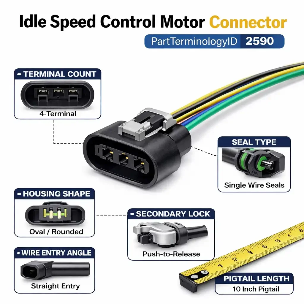
Idle Speed Control Motor Connector (PartTerminologyID 2590):Connector Variants, Motor Types, and the Catalog Fields That Stop Returns
PartTerminologyID 2590, the Idle Speed Control Motor Connector, sits one ID away from PartTerminologyID 2589, the Idle Air Control Valve Connector. The proximity is not a coincidence. The two parts serve related but distinct functions, they appear on overlapping vehicle populations, and they generate the same category of catalog problems: listings that capture vehicle fitment accurately but fail to describe the physical connector well enough for a buyer to confirm they are ordering the right variant.
The ISC motor connector is not the same part as the IAC valve connector, and the distinction matters more than the terminology suggests. Where the IAC valve is a solenoid that meters bypass air, the idle speed control motor is a stepper motor or DC motor that physically repositions the throttle plate or an air bypass plunger using incremental mechanical movement. The connectors that serve these two devices differ in terminal count, circuit requirements, housing geometry, and in some cases the number of wires required to drive a multi-phase stepper motor.
If your catalog groups ISC motor connectors with IAC valve connectors because both touch idle speed management, you will generate returns. If your listings for ISC motor connectors do not capture terminal count, motor type, housing shape, and wire entry, you will generate returns. This guide covers everything needed to catalog PartTerminologyID 2590 correctly.
PCdb Status for PartTerminologyID 2590
Where this part sits in the standards framework.
PartTerminologyID
◦ 2590 in both current PIES 7.2 / PCdb and future PIES 8.0 / PCdb 2.0. No change on migration.
Terminology Name
◦ Idle Speed Control Motor Connector. No rename in PIES 8.0.
Category
◦ Engine
SubCategory
◦ Fuel Delivery
Status
◦ Active in both schema versions.
As with PartTerminologyID 2589, the terminology name describes the circuit function, not the physical configuration. Idle Speed Control Motor Connector tells you what the connector serves. It does not tell you how many terminals are required to drive the motor, what control strategy the ECM uses, or what the connector housing looks like. That information belongs in the catalog data, and it is the information most commonly missing from aftermarket listings in this category.
The ISC Motor vs. the IAC Valve: Why the Distinction Matters
Before getting into connector variants, the functional difference between the ISC motor and the IAC valve needs to be clear, because it drives the entire connector variance picture for PartTerminologyID 2590.
How the Idle Air Control Valve Works
The IAC valve is a solenoid. The ECM sends a pulse-width modulated signal to open or close a bypass air passage around the throttle plate. The valve has two states: open and closed, with varying degrees of opening controlled by the duty cycle of the signal. Most IAC valve solenoids are two-terminal devices: one terminal for the control signal and one for ground, or in some designs, two terminals for a two-coil solenoid. The circuit is simple and the connector reflects that.
How the Idle Speed Control Motor Works
The ISC motor is a stepper motor or DC motor. It does not simply open and close a valve. It moves a mechanical actuator in precise incremental steps, either repositioning a throttle stop that limits how far the throttle plate can close, or driving a plunger in and out of a bypass air passage with fine positional control.
A stepper motor requires multiple phase windings to produce rotation. A two-phase bipolar stepper motor, which is one of the most common designs in automotive ISC applications, requires four terminals: two for each phase winding. A two-phase unipolar stepper motor requires more. A simple DC motor with a position feedback potentiometer may require five or six terminals depending on how many circuits are integrated into the connector.
The connector for an ISC motor is therefore fundamentally different from the connector for an IAC valve solenoid. More terminals, more complex circuit requirements, and in many cases a larger and more complex housing to accommodate the additional wiring.
Why Buyers Confuse the Two
The confusion happens because both parts connect to the idle speed management circuit on the engine. A buyer who searches for an idle connector on their vehicle may not know whether their engine uses an IAC valve or an ISC motor. On some platforms both systems appeared across the model run. On others the distinction was made by engine variant or market. A listing that appears under both IAC and ISC search terms, or a catalog that uses the terms interchangeably, sends the wrong connector to a significant percentage of buyers.
The first function of the PartTerminologyID distinction between 2589 and 2590 is to prevent this confusion at the catalog level. The second function is to ensure that ISC motor connectors, which require more precise terminal and motor-type data than IAC valve connectors, are listed with the additional fields their complexity demands.
KEY DISTINCTION
IAC valve: solenoid, typically 2 terminals, simple duty-cycle signal. ISC motor: stepper or DC motor, typically 4 to 6 terminals, multi-phase or multi-circuit signal. A connector for one will not serve the other. Catalog separation at the PartTerminologyID level is the correct practice. Grouping them under a generic idle connector category is a return waiting to happen.
What the ISC Motor Connector Actually Connects To
Understanding the motor design on the other end of the connector is the starting point for any ISC connector catalog entry, because the motor design determines the terminal count, the circuit map, and the connector housing requirements.
Two-Phase Bipolar Stepper Motor
This is the most common ISC motor design in the aftermarket. It uses two independent phase windings, and the ECM drives each phase in sequence to rotate the motor in precise steps. Each phase winding has two terminals, positive and negative, giving a total of four terminals for the connector. The ECM can reverse the current direction in each phase to control both the direction and the magnitude of the motor movement.
Four-terminal ISC motor connectors are the largest segment of PartTerminologyID 2590 in the aftermarket. They appear on a wide range of domestic and import applications from the mid-1980s through the mid-2000s, when throttle-by-wire systems began replacing mechanical idle control on many platforms.
Two-Phase Unipolar Stepper Motor
The unipolar stepper motor uses center-tapped phase windings, meaning each phase has a center tap that connects to a common power supply, and the ECM switches current through each half-winding in sequence. This requires more terminals than the bipolar design because the center taps are brought out to separate connector pins. Unipolar ISC motors may use five or six terminals depending on whether the two center taps share a common terminal or are brought out separately.
These connectors are less common in the aftermarket than four-terminal bipolar designs, but they appear on specific domestic applications, notably some Chrysler and Ford platforms, and on several Toyota applications. They must be cataloged separately from four-terminal connectors. The terminal count difference is not a minor distinction. These connectors are physically incompatible with bipolar motor applications.
DC Motor With Position Feedback
Some ISC motor designs use a conventional DC motor rather than a stepper motor, with a separate position feedback potentiometer built into the motor assembly. The DC motor itself requires two terminals for power and ground. The potentiometer requires three additional terminals: a reference voltage, a wiper signal, and a ground. This gives a total of five terminals in the connector, though in some designs the potentiometer ground is shared with the motor ground, reducing the count to four.
DC motor ISC connectors appear on several Honda and Mitsubishi applications and on some domestic applications from the late 1980s and early 1990s. They look superficially similar to four-terminal stepper motor connectors in terminal count but are wired to a completely different circuit. A connector built for a stepper motor application will not serve a DC motor with potentiometer feedback, and vice versa.
Throttle Position Actuator Integrated Designs
On some platforms, particularly later Toyota and Honda applications approaching the transition to throttle-by-wire, the ISC motor function is integrated into a more complex throttle body actuator that also incorporates throttle position sensor signals. These connectors may have six or more terminals and are application-specific to the point where connector family name and terminal count alone are insufficient identifiers. These listings require explicit OEM cross-reference or throttle body design notes to prevent returns.
The Complete Variant Universe for PartTerminologyID 2590
Every attribute below is a return driver when it is absent from the listing. The ISC motor connector carries more of these attributes per SKU than the IAC valve connector because the underlying motor technology is more varied.
1. Terminal Count
Terminal count is the first filter for ISC motor connector compatibility and the most commonly omitted field in aftermarket listings. Unlike the IAC valve connector category where two terminal counts cover most of the market, ISC motor connectors appear in four, five, and six terminal configurations depending on the motor design.
• 4-terminal. The standard configuration for two-phase bipolar stepper motor applications. The most common in the aftermarket.
• 5-terminal. Appears on unipolar stepper motor applications with a shared center tap ground, and on DC motor applications with a three-wire potentiometer where the ground is shared with the motor circuit.
• 6-terminal. Appears on unipolar stepper motor applications with separate center taps for each phase, and on DC motor applications where the potentiometer ground is kept isolated from the motor ground.
• 4-terminal with integrated sensor. Some applications use a 4-terminal connector that serves a DC motor plus a single-circuit position sensor. Terminal count matches the bipolar stepper count but the circuit function is entirely different.
Terminal count must appear in the title and the item specifics on every listing. A four-terminal connector listing that competes in search results with a six-terminal connector listing for the same vehicle application will send the wrong part to a significant number of buyers who assume all connectors for their vehicle are the same.
2. Motor Type Designation
Terminal count alone does not fully identify the connector because different motor types can share terminal counts while using incompatible connector designs. The motor type designation must be captured in the listing alongside terminal count.
• Bipolar stepper. Four terminals, two-phase drive, no center tap. The most common ISC motor design in the aftermarket.
• Unipolar stepper. Five or six terminals, center-tapped windings. Physically and electrically incompatible with bipolar stepper connectors even when housing geometry is similar.
• DC motor with potentiometer feedback. Four or five terminals. Incompatible with stepper motor connectors regardless of terminal count match.
• Integrated actuator. Six or more terminals. Application-specific. Must be identified by OEM part reference or throttle body design rather than generic motor type.
The motor type note in a listing does more than prevent a wrong connector order. It helps the buyer confirm they have identified their motor correctly. A buyer who is unsure whether their application uses a stepper motor or a DC motor ISC design can use the motor type note in the listing as a confirmation check against the component they are looking at on their engine.
3. Connector Body Shape and Housing Profile
ISC motor connectors are larger than most IAC valve connectors because they carry more terminals and in some cases more substantial wiring gauges for the motor phase currents. The housing profile varies significantly across the connector families used by different manufacturers.
• Rectangular multi-pin housing. The most common profile for four-terminal bipolar stepper applications on domestic platforms. A wide, flat housing with the terminals arranged in a single row or two rows of two.
• Compact square housing. Appears on some import applications with four-terminal designs. The terminal arrangement is in a 2x2 grid rather than a single row, giving the housing a more square profile.
• Extended rectangular housing. Used on five and six terminal applications where the additional terminals require a longer housing body.
• Dual-connector design. Some ISC motor applications use two separate connectors on the same motor body: one for the motor windings and one for the position feedback sensor. These must be listed as a pair, not as a single connector, to prevent buyers from ordering only one of the two connectors needed for a complete repair.
The housing profile should be described in words in the item specifics. A face-on photograph shows terminal count and layout but does not communicate housing depth, latch position, or secondary lock type. Written shape descriptions are more useful for buyers working from a disassembled engine who cannot compare the connector visually.
4. Wire Entry Angle
ISC motors are mounted in tight locations on the throttle body or intake manifold, and the harness routing around these locations constrains which wire entry angle will work without stressing the connector or the harness.
• Straight entry. The wire bundle exits in line with the connector axis. Used where the harness runs away from the motor along the direct approach path.
• 90-degree entry. The wire bundle exits perpendicular to the mating face. Used where the harness must turn immediately after the connector to route along the throttle body or intake manifold surface.
Wire entry angle is less frequently cited as a return reason for ISC motor connectors than for IAC valve connectors, but it is still a source of installation complaints when the connector is correct in every other respect but the wire routing creates harness stress at the connector body. It belongs in the item specifics.
5. Seal Type
ISC motors are mounted in engine bay locations that vary considerably in exposure to water, oil vapor, and heat cycling. The sealing specification of the replacement connector should match or exceed the OE design for the specific mounting location.
• Single wire seal per terminal. Each terminal cavity has an individual wire seal. Standard on most late-model and weather-exposed applications.
• Peripheral face seal. A single rubber seal on the connector mating face that seals against the motor housing. Used on some applications in addition to wire seals, or as the primary seal on older designs.
• Unsealed. Some older or lower-exposure applications use unsealed connectors. Note this explicitly because buyers in humid climates may want to upgrade to a sealed design if available.
6. Secondary Lock and Retention
ISC motors are subject to engine vibration, and connector retention matters more on motor connectors than on some other fuel system connectors because intermittent contact on a stepper motor circuit can cause erratic idle behavior that is difficult to diagnose. The secondary lock design affects both installation and long-term retention reliability.
• Integral secondary lock with push-release tab. Built into the connector housing, released by pressing a tab before unlatching.
• Clip-on secondary lock. A separate plastic clip that slides onto the connector body after mating to add retention. Some aftermarket connectors omit the secondary lock clip even when the OE connector included one.
• Wire dress secondary lock. A tie point or loop on the connector body that allows the wire bundle to be dressed back against the connector for added retention. Less common.
• No secondary lock. Present on some older domestic applications. Note explicitly.
7. Pigtail Length and Wire Gauge
ISC motor connectors are sold as pigtails, and the same length and gauge considerations that apply to IAC valve connector pigtails apply here. The motor phase currents in a stepper motor application are typically higher than the control signals in an IAC solenoid circuit, which means wire gauge matters more in this category.
• Pigtail length. State in inches. The standard offering for most applications is 8 to 12 inches. For motors mounted in locations with limited harness access, a longer pigtail may be necessary to route the splice outside the heat zone.
• Wire gauge. Stepper motor phase windings typically draw more current than solenoid control signals. Wire gauge in ISC motor pigtails is commonly 16 or 18 AWG. State the gauge per wire. On multi-terminal connectors where the motor wires and sensor wires use different gauges, note both.
• Wire count. On dual-connector or integrated sensor designs, the total wire count in the pigtail may not equal the terminal count in the connector. Note this when it applies.
OEM ISC Motor and Connector Designs by Platform
The connector families used in ISC motor applications vary more by manufacturer than in most other connector categories because the motor technology itself varied significantly across manufacturers and model generations. The following platform notes help explain why catalog splits are necessary and where they need to happen.
Chrysler Stepper Motor ISC Applications
Chrysler used a stepper motor idle speed control design extensively on fuel-injected four-cylinder and V6 applications from the mid-1980s through the late 1990s. The Chrysler ISC stepper motor connector is a four-terminal design with a distinctive rectangular housing and a slide-lock secondary retention that differs from the connector family used on Chrysler IAC solenoid applications. These connectors are well-represented in the aftermarket and the catalog split between the stepper motor connector and the solenoid connector is important for this manufacturer because both designs appear on overlapping vehicle fitment ranges.
A specific catalog trap on Chrysler applications: the 2.2 and 2.5 four-cylinder engines used different ISC motor designs at different points in their production run, and the connector changed accordingly. Application data that only captures year and engine size will group the early and late designs together. The production date break must appear in the fitment notes.
Ford Throttle Kicker and ISC Motor Applications
Ford used a variety of idle speed control approaches across its EFI application range. Some Ford applications use a dedicated ISC stepper motor with a four-terminal connector. Others use a throttle kicker solenoid that is functionally different from a stepper motor but may appear in searches for idle speed control components. Catalog entries for Ford ISC motor connectors must clearly distinguish stepper motor applications from solenoid-based idle control applications, because the connectors are not interchangeable and the connector families used for the two designs are different.
GM Stepper Motor Applications
General Motors used stepper motor idle control on many TBI and TPI applications of the late 1980s and early 1990s. The GM ISC stepper motor connector is a four-terminal design, typically in the Packard or Delphi connector family, with a rectangular housing that is larger than the two-terminal IAC solenoid connector used on other GM applications of the same era. The key catalog issue on GM applications is that some engine families were produced with both stepper motor ISC and solenoid IAC designs depending on model year and market, and the same year, make, model, and engine can require either type. The catalog must split by production date or option package where this applies.
Toyota and Honda Stepper Motor Applications
Toyota used stepper motor ISC designs extensively on the 22RE, 2VZ, and several other engine families from the mid-1980s through the mid-1990s. The Toyota ISC stepper connector is typically a four-terminal design with an oval or rounded housing that differs from the rectangular housing used on domestic stepper motor applications. Honda used a similar stepper motor design on several late 1980s and early 1990s applications, with connectors that share the oval housing profile.
The cataloging challenge on import stepper motor applications is that the oval housing is a critical differentiator from domestic rectangular-housing connectors with the same terminal count. A listing for a Toyota ISC connector that only says 4-terminal without noting the oval housing will result in buyers ordering rectangular domestic connectors that will not fit the Toyota motor housing. The shape description must appear in the title on import applications.
Mitsubishi DC Motor ISC Applications
Mitsubishi used a DC motor with potentiometer feedback for idle speed control on several late 1980s and early 1990s applications, including the widely sold Galant, Eclipse, and related platforms. The connector for these applications has four or five terminals and serves both the DC motor circuit and the feedback potentiometer circuit in the same housing. This connector is physically incompatible with stepper motor connectors even when the terminal count matches. Listings for Mitsubishi ISC connector applications must note the DC motor with feedback design to prevent buyers from ordering a stepper motor connector.
PLATFORM SPLIT SUMMARY
Every platform that used both a stepper motor ISC design and a solenoid IAC design across its model run requires a catalog split. The split is not cosmetic. The connectors are physically incompatible. Year, make, and model fitment data alone will not make the split. Production date, engine variant, or system type notes must be in the application data.
Catalog Fields That Reduce Returns for PartTerminologyID 2590
The minimum field set for accurate ISC motor connector listings. Each field maps to a specific return pattern when it is missing.
Core Identification Fields
Terminal Count
◦ 4, 5, or 6. Required in the title and item specifics. Do not leave this to the photograph.
Motor Type
◦ Bipolar stepper, Unipolar stepper, DC motor with potentiometer, or Integrated actuator. Required. This is the differentiator that terminal count alone cannot provide.
Connector Body Shape
◦ Rectangular single-row, Rectangular 2x2, Extended rectangular, Oval, or Dual-connector. Required. Written description, not only a photograph.
Wire Entry Angle
◦ Straight or 90-degree. Required.
OEM Connector Family
◦ Delphi, Packard, Bosch, Sumitomo, or other manufacturer family name when known. Provides a verification reference for technical buyers.
Sealing and Retention Fields
Seal Type
◦ Single wire seal, Peripheral face seal, or Unsealed.
Secondary Lock Type
◦ Integral push-release, Clip-on secondary lock included, or None. Note if the OE connector had a secondary lock that the replacement does not include.
Wire and Pigtail Fields
Pigtail Length
◦ State in inches. Required on every pigtail listing.
Wire Gauge
◦ State in AWG per wire. Note if motor wires and sensor wires use different gauges in the same connector.
Wire Count
◦ State the total number of wires in the pigtail. On dual-connector designs, state the wire count per connector.
Wire Colors
◦ Note if wire colors match OE convention. Technicians use color coding during installation and splicing.
Motor Compatibility and Application Notes
Motor Compatibility Statement
◦ A plain-language statement naming the ISC motor design this connector serves. For example: Fits Chrysler four-terminal bipolar stepper ISC motor. Does not fit solenoid IAC valve connectors.
Production Date or VIN Break
◦ Required when a platform used multiple ISC motor or connector designs across a model run. Model year is not sufficient.
Dual-Connector Note
◦ When the ISC motor uses two separate connectors, state this explicitly. List both connectors and note that both are required for a complete repair.
IAC vs. ISC Application Note
◦ On platforms where both IAC solenoid and ISC stepper motor designs appear, note which system this connector serves and which it does not.
The Most Common Listing Mistakes for PartTerminologyID 2590
These are the patterns that generate returns in this category. None require a product change to fix. All require a catalog change.
Mistake 1: Terminal Count Not Stated
An ISC motor connector listing that does not state terminal count will convert buyers from multiple incompatible applications. Four, five, and six terminal connectors all list to overlapping vehicle populations on some platforms. A buyer ordering without a terminal count reference has no way to verify compatibility before the part arrives. Terminal count goes in the title.
Mistake 2: Motor Type Not Identified
Bipolar stepper, unipolar stepper, and DC motor with potentiometer connectors can share terminal counts while being physically incompatible. A four-terminal connector listing that does not identify the motor type will be ordered by buyers on stepper motor applications and DC motor applications alike. Half of them will receive the wrong connector. Motor type is a required field, not optional context.
Mistake 3: ISC Motor Connector Listed as IAC Valve Connector
This happens when catalog data uses idle connector as a search tag for both PartTerminologyID 2589 and 2590, or when a supplier catalog groups both under a single idle control category. The result is buyers who need a four-terminal ISC stepper connector receiving a two-terminal IAC solenoid connector, and returning it as the wrong part. The PartTerminologyID separation exists precisely to prevent this. Honor it in the catalog data.
Mistake 4: Dual-Connector Applications Listed as Single Connector
When an ISC motor uses two separate connectors on the motor body, listing only one of them results in a customer who installs the pigtail they received, finds the second connector still unmated, and returns the part as incomplete. The listing must state that the motor uses two connectors, list both, and make clear that both are required for a complete repair. If only one connector is being sold, the listing must explicitly note that the second connector is sold separately.
Mistake 5: Housing Shape Not Described for Import Applications
On Toyota, Honda, and Mitsubishi applications where the ISC motor connector uses an oval or rounded housing, omitting the shape description allows buyers to order rectangular-housing domestic connectors with matching terminal counts. The connectors will not fit. Oval housing must appear in the title on import applications, not only in a product photograph.
Mistake 6: Production Date Break Not Noted on Chrysler and GM Applications
Chrysler and GM applications that used multiple ISC motor or connector designs across a production run are among the highest-return applications in this category. A fitment row that covers a full model generation without a production date break will send the wrong connector to buyers whose vehicle falls on the other side of the design change. The production date break must appear in the application data, not as a general verify fitment disclaimer but as a specific date cutoff with guidance on which connector applies to which production range.
Mistake 7: Wire Gauge Not Specified for Motor Wires
ISC stepper motor phase currents are higher than IAC solenoid control currents. A pigtail built with 20 AWG wire on a stepper motor application that originally used 16 AWG creates a circuit that may overheat the splice under sustained idle correction demand. Wire gauge must be specified on ISC motor connector listings, and it must match the OE specification for the application.
Marketplace-Ready Listing Standards for PartTerminologyID 2590
Required Title Elements
A compliant title for this category should include: part type as Idle Speed Control Motor Connector, terminal count, motor type abbreviation when space allows, and housing shape when the application is an import with a non-rectangular housing.
Example for a domestic four-terminal bipolar stepper application:
Idle Speed Control Motor Connector, 4-Terminal, Bipolar Stepper, Rectangular Housing, 10 Inch Pigtail
Example for a Toyota oval-housing application:
Idle Speed Control Motor Connector, 4-Terminal, Stepper Motor, Oval Housing, Fits Toyota 22RE ISC
Example for a Mitsubishi DC motor application:
Idle Speed Control Motor Connector, 4-Terminal, DC Motor with Feedback Potentiometer, Fits Mitsubishi ISC
Required Bullet Points
These bullets should appear on every ISC motor connector listing:
• TERMINALS: State the exact count. 4-terminal, 5-terminal, or 6-terminal.
• MOTOR TYPE: Bipolar stepper, Unipolar stepper, DC motor with potentiometer, or Integrated actuator.
• HOUSING SHAPE: Rectangular, Oval, Square, or Extended rectangular. Written description required.
• WIRE ENTRY: Straight or 90-degree.
• SEAL TYPE: Sealed with wire seals, Peripheral face seal, or Unsealed.
• PIGTAIL LENGTH: State in inches.
• WIRE GAUGE: State in AWG. Note if motor and sensor wires differ.
• MOTOR COMPATIBILITY: Plain-language statement of which ISC motor design this connector fits and which it does not.
Motor Compatibility Statement Templates
TEMPLATE A: DOMESTIC STEPPER APPLICATION
Fits: 4-terminal bipolar stepper ISC motor on listed applications. Does not fit: 2-terminal IAC solenoid connectors, unipolar stepper applications, or DC motor ISC designs. Verify motor type before ordering if application uses both IAC solenoid and ISC stepper motor designs across its production run.
TEMPLATE B: IMPORT OVAL HOUSING APPLICATION
Fits: Toyota/Honda stepper ISC motor with oval 4-terminal connector housing. Does not fit: rectangular-housing ISC connectors or IAC solenoid connectors. Oval housing shape distinguishes this connector from domestic rectangular-housing designs with the same terminal count.
TEMPLATE C: DC MOTOR WITH POTENTIOMETER
Fits: DC motor idle speed control with integrated position feedback potentiometer. 4 or 5 terminals serving both motor circuit and potentiometer circuit. Not compatible with stepper motor ISC connectors. Verify motor design is DC with feedback before ordering.
Application Data Strategy for High-Return Applications
Chrysler 2.2 and 2.5 Four-Cylinder Applications
These engines appear across a very large range of vehicles from the mid-1980s through the mid-1990s, including Dodge, Plymouth, and Chrysler passenger cars, minivans, and some light truck applications. The ISC motor design changed during this production span and the connector changed with it. Application data for these engines must include a production date qualifier for any fitment row where the ISC connector design changed. A note stating Fits through a specific date with early-design ISC motor and a companion note for the revised design is the correct approach. A single fitment row covering the full engine production span will generate returns on every order that falls on the wrong side of the design break.
GM TBI and TPI V6 and V8 Applications
GM throttle body injection and tuned port injection applications from the late 1980s and early 1990s used stepper motor ISC designs on many engine families. The challenge in cataloging these applications is that some engine families used both ISC stepper motor and IAC solenoid designs at different points in production, and some used both simultaneously on different vehicle applications sharing the same engine. Application data must split by production date or body style where the idle control technology differed. A single fitment row covering all applications of a given GM engine family without noting the ISC versus IAC split will produce a high return rate on misrouted orders.
Toyota 22RE and Related Applications
The Toyota 22RE engine is a high-volume application for ISC motor connector replacement because the engine was produced in large numbers over a long span and is still in service in trucks and 4Runners in large numbers. The ISC motor connector on these applications uses the oval housing that distinguishes it from domestic rectangular connectors. Catalog data must include the oval housing designation in the fitment notes and the item specifics, not just in the product title. Buyers who search by vehicle and sort by terminal count will find both rectangular and oval connectors in their results. The housing shape description in the specifics is the field that enables them to make the correct choice.
Mitsubishi DSM and Related Applications
Mitsubishi applications on the Eclipse, Galant, and related platforms from the late 1980s through the mid-1990s use the DC motor with potentiometer feedback ISC design. These connectors are frequently misidentified in the aftermarket because the terminal count on some variants matches the four-terminal bipolar stepper count and the connector housing profiles are not obviously different from a photograph. Listings for Mitsubishi ISC connector applications must state DC motor with feedback in the motor type field and must include a compatibility statement that clearly differentiates these connectors from stepper motor designs.
FAQ for Idle Speed Control Motor Connector (PartTerminologyID 2590)
What is the difference between an ISC motor connector and an IAC valve connector?
The IAC valve connector serves a solenoid that opens and closes a bypass air passage. It typically has two terminals and carries a simple duty-cycle control signal. The ISC motor connector serves a stepper motor or DC motor that moves a mechanical actuator to control idle speed. It requires four, five, or six terminals to drive the motor phases or to carry both the motor circuit and a feedback sensor signal. The two connectors are not interchangeable. Using the PCdb PartTerminologyID correctly, 2589 for IAC valve connectors and 2590 for ISC motor connectors, is how the catalog keeps these separated at the search level.
My connector has four terminals. Why does it not fit my ISC motor?
Four-terminal ISC connectors exist in multiple incompatible designs: bipolar stepper motor connectors, unipolar stepper motor connectors with shared grounds, and DC motor with potentiometer connectors. All may have four terminals but the housing geometry, pin spacing, and circuit assignment differ across these designs. Verify the motor type on your vehicle against the motor type listed for the connector. If the motor type matches but the connector still does not mate, compare the housing shape of your original connector against the replacement.
My vehicle has both an IAC valve and an ISC motor. Which connector do I need?
Some vehicles use both systems simultaneously or used different systems at different points in production. The component you are replacing determines which connector you need. If the part on your engine is a solenoid-type valve with two wires, you need PartTerminologyID 2589. If the part on your engine is a stepper motor or DC motor with four or more wires, you need PartTerminologyID 2590. If you are unsure which you have, count the wires on the original connector and identify the motor body design before ordering.
Why does my stepper motor ISC run erratically after connector replacement?
Erratic stepper motor behavior after connector replacement is usually caused by one of three issues. First, a terminal that is not fully seated in the connector housing creates intermittent contact on a motor phase, causing the stepper to miss steps. Second, a wire gauge that is lighter than the OE specification creates additional resistance on the motor phase circuit, which affects the current that reaches the winding. Third, an incorrect connector that mates physically but maps the phase wires to different pins than the OE design will cause the motor to run in the wrong direction or with incorrect phase sequencing. Verify terminal seating, wire gauge, and pin assignment against the OE connector specification.
What happens if I use a connector without a secondary lock on a motor that originally had one?
The primary latch on most ISC motor connectors is sufficient for initial installation, but without a secondary lock the connector is more vulnerable to backing out under sustained engine vibration. On an ISC stepper motor circuit, a connector that intermittently loses contact on one phase produces an idle quality symptom that is difficult to diagnose because it appears and disappears with vibration rather than failing completely. If your original motor connector had a secondary lock, use a replacement that includes one.
The original connector on my motor has two separate housings. Do I need both?
Yes. If the ISC motor on your vehicle uses a dual-connector design, both connectors are part of the electrical connection to the motor. One connector typically serves the motor drive windings and the other serves a position feedback sensor or a separate reference circuit. Replacing only one connector leaves the other circuit unrepaired and may prevent the motor from functioning correctly even after the first connector is installed. Verify that the listing you are ordering from includes both connectors, or that you are ordering both separately.
Catalog Quality Checklist for PartTerminologyID 2590
Run this checklist on every ISC motor connector listing before it goes live. An unanswered item is a gap that will produce returns.
1. State terminal count in the title and item specifics. 4, 5, or 6. Do not leave it to the photograph.
2. Identify motor type. Bipolar stepper, unipolar stepper, DC motor with potentiometer, or integrated actuator. This is the field that terminal count alone cannot replace.
3. Describe housing shape in words. Rectangular, oval, square, or extended rectangular. Written description required alongside photos.
4. Note wire entry angle. Straight or 90-degree.
5. Specify pigtail length in inches.
6. State wire gauge in AWG. Note separately for motor wires and sensor wires if they differ.
7. Document seal type and secondary lock type. Note if the replacement omits a secondary lock that the OE connector included.
8. Write a motor compatibility statement. Name the ISC motor design this connector fits. State which common designs it does not fit.
9. Check for ISC vs. IAC split on the application. If the platform used both ISC stepper motor and IAC solenoid designs, note clearly which this connector serves.
10. Check for dual-connector applications. If the motor uses two connectors, state this and list both. Do not sell one without disclosing the second is required.
11. Check for production date breaks. If the ISC connector design changed mid-generation, split the fitment row and note the date cutoff.
Final Thoughts
The Idle Speed Control Motor Connector is a more technically demanding catalog entry than most connectors in the fuel delivery category. The terminal count range is wider, the motor type distinctions are material, the housing shapes vary by manufacturer, and the overlap with IAC valve connector search results creates a category-level confusion problem that catalog data has to actively solve rather than passively accept.
The fields required to catalog this part correctly are not difficult to obtain for a seller who has the physical product in hand. Terminal count, motor type, housing shape, wire gauge, and pigtail length are observable facts about the connector. The motor compatibility statement is one sentence written once per SKU. The production date break is a note added to the fitment row when the application data reveals a design change.
None of these are expensive. All of them reduce returns. In a category where every returned connector costs more in handling and restocking than it earned in margin, the investment in accurate catalog data is the highest-return activity available.
Catalog it completely and specifically. Small part, significant complexity, zero tolerance for vague listings.