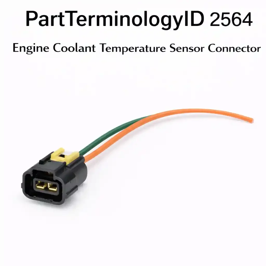
Engine Coolant Temperature Sensor Connector (PartTerminologyID 2564): Why Terminal Count, Circuit Function, Sensor Housing Profile
Written by Arthur Simitian | PartsAdvisory
PartTerminologyID 2564, Engine Coolant Temperature Sensor Connector, is the wiring harness connector body that mates with the engine coolant temperature sensor, providing the electrical interface between the vehicle's powertrain control module and the thermistor terminals that carry the analog voltage signal the PCM uses to determine engine coolant temperature. That definition covers the function correctly. It does not specify the terminal count, which is one terminal on older single-wire temperature sender designs that ground through the sensor threads into the cylinder head or thermostat housing and carry only a variable resistance signal wire to the instrument cluster, two terminals on the dominant PCM-input ECT sensor design used on OBD-II and pre-OBD-II fuel-injected engines where the PCM supplies a 5-volt reference voltage and monitors the return signal through two dedicated harness wires, or three terminals on dual-function designs used on Subaru, Toyota, and some European applications where a single sensor housing contains two independent thermistor elements, one for the PCM and one for the instrument cluster gauge, with each element requiring its own terminal circuit, the connector body housing series designation, the circuit function of the sensor the connector is matched to, whether the connector is for a PCM-input ECT sensor that determines fuel injection enrichment, ignition advance, idle speed, cooling fan activation, and cold-start operating strategy, or for a temperature gauge sender that drives only the instrument cluster needle and has a different thermistor calibration curve than the PCM sensor even when both components are mounted adjacent to each other on the same thermostat housing, the contact resistance threshold that matters at this connector's terminal interface given the NTC thermistor circuit's sensitivity, the pigtail wire gauge and length, and whether the listing covers the connector body only or a pigtail assembly. A listing under PartTerminologyID 2564 that provides vehicle year, make, and model without the terminal count, the circuit function designation, and the sensor housing series cannot be evaluated by any technician replacing a heat-melted, coolant-corroded, or physically broken ECT sensor connector at the thermostat housing, intake manifold, or cylinder head port that is the sensor's mounting location.
For sellers, PartTerminologyID 2564 is the connector PartTerminologyID in this series where a connector fault produces the widest range of downstream engine management symptoms, rich cold-start mixture, extended open-loop operation, sluggish warm-up enrichment removal, incorrect ignition timing at all temperatures, suppressed cooling fan activation, and failed OBD-II readiness monitors, because the ECT sensor is the PCM's primary correction factor for nearly every fuel, timing, and emissions control calculation it performs during the cold-start and warm-up phase that constitutes the most emissions-intensive and drivability-sensitive portion of every trip. A connector with elevated contact resistance adds to the sensor's thermistor resistance in series, making the PCM read a falsely low coolant temperature because additional resistance in the circuit produces a higher signal voltage on the 5-volt divider network, which the PCM interprets as a colder engine than the actual coolant temperature. A connector with an open-circuit terminal produces the maximum possible signal voltage, the full 5-volt reference, which the PCM interprets as a coolant temperature of approximately negative 40 degrees Celsius, the lowest extreme of the sensor's calibration range, causing the engine to run with full cold-start enrichment, high idle speed, and open-loop fuel control indefinitely. Neither the elevated-contact-resistance condition nor the open-circuit condition sets a fault code immediately on most applications; both produce symptoms that the technician and the vehicle owner observe as a running condition problem, rough idle, rich exhaust, poor fuel economy, black smoke, sluggish warm-up behavior, that they attribute to the thermostat, the fuel injectors, or the oxygen sensors before identifying the ECT sensor connector as the cause.
The additional complexity specific to PartTerminologyID 2564 is the circuit function argument. The same thermostat housing on many domestic and import vehicles carries two sensors within millimeters of each other: the ECT sensor for PCM input and the temperature sender for the instrument cluster gauge. These two components use similar connector body profiles on many applications but serve entirely different circuits with different thermistor calibration curves. A PCM-input ECT sensor connector installed on a temperature gauge sender will either fail to seat because the housing profiles differ, or will seat but leave the gauge sender's single terminal unconnected when the two-terminal ECT connector engages only one of the sender's terminals. A temperature gauge sender connector installed on a PCM-input ECT sensor will leave the PCM's reference voltage terminal unconnected and connect only one wire to the signal return terminal, producing a partial circuit that sets ECT sensor fault codes and places the PCM in failsafe mode from the first key-on.
For sellers, the listing under this PartTerminologyID is only useful if it specifies the sensor housing designation as the primary fitment attribute, the terminal count, the circuit function designation explicitly distinguishing PCM-input ECT sensors from gauge temperature senders, the connector body housing series, the wire gauge, and whether the listing is a connector body only or a pigtail assembly. Without those attributes, the listing enables the circuit function mismatch that places the PCM in failsafe mode, the contact resistance accumulation that extends rich cold-start enrichment indefinitely without setting a fault code, and the terminal count mismatch on dual-function three-terminal sensors that leaves either the PCM circuit or the gauge circuit without a connection.
What the Engine Coolant Temperature Sensor Connector Does
Carrying the PCM's 5-volt reference and signal return on the dominant two-terminal design
On all fuel-injected vehicles built from the mid-1980s onward, the PCM-input ECT sensor is a two-terminal NTC thermistor, Negative Temperature Coefficient, meaning its resistance decreases as temperature increases. The PCM supplies a regulated 5-volt reference voltage to one terminal, and the signal returns to a PCM sensor ground through the second terminal. Between the two terminals sits the thermistor element, whose resistance ranges from approximately 10,000 ohms at 32 degrees Fahrenheit to under 200 ohms at a fully warm engine temperature of 200 to 210 degrees Fahrenheit. The PCM monitors the voltage at the signal return terminal, the voltage divider output between the fixed reference resistor inside the PCM and the variable thermistor resistance, and uses that voltage to determine coolant temperature. At cold start, the thermistor's high resistance allows most of the 5-volt reference to appear at the signal terminal: typically 3.5 to 4.5 volts. At normal operating temperature, the thermistor's low resistance drops the signal terminal voltage to typically 0.47 to 1.45 volts.
The connector carries these two circuits, reference supply and signal return, with terminal contact resistance that must remain below the threshold at which the added series resistance meaningfully shifts the voltage divider output. Because the thermistor's resistance curve is steep at cold temperatures (small temperature changes produce large resistance changes near the cold extreme) and shallow at operating temperature (small temperature changes produce only small resistance changes near the hot extreme), the connector's contact resistance has asymmetric effects across the operating range. At cold start, even 2 ohms of contact resistance at the signal terminal adds negligible error relative to the thermistor's 10,000-ohm resistance, and the PCM reads an essentially accurate cold temperature. As the engine warms and the thermistor resistance drops toward 200 ohms at operating temperature, the same 2 ohms of contact resistance becomes a 1 percent addition to the total circuit resistance, producing a meaningful voltage offset that makes the PCM read the engine as approximately 5 to 10 degrees Fahrenheit colder than the actual coolant temperature. The practical consequence is that the PCM holds the fuel trim at a slightly richer setting than a fully warm engine requires, never quite entering the leanest portion of its closed-loop fuel trim authority, and the cooling fans may activate at a slightly higher coolant temperature than their calibrated threshold because the PCM's temperature reading lags the actual temperature by the connector's resistance contribution.
Why the ECT sensor connector is the "master sensor" connector in the engine management harness
The ECT sensor's signal affects more PCM calculations than any other individual sensor input. The PCM uses the ECT signal to determine the cold-start fuel enrichment multiplier that adds extra fuel on top of the base injection duration during the first minutes of operation; the open-loop fuel control period before the oxygen sensors reach operating temperature and the PCM switches to closed-loop correction; the idle air control valve position that sets fast idle speed during warm-up; the EGR valve suppression that keeps exhaust gas recirculation disabled until the engine is warm; the evaporative emissions purge valve suppression that keeps canister purge disabled until coolant temperature reaches threshold; the ignition advance correction that retards timing from the base map during cold operation; and the cooling fan activation relay command that turns on the electric radiator fans when coolant reaches the fan-on temperature threshold. Every one of these calculations uses the ECT signal as an input, and every one will execute incorrectly if the ECT connector has elevated contact resistance, an intermittent connection, or a complete open circuit.
On OBD-II vehicles, the ECT signal also affects the readiness monitor completion criteria for the catalyst monitor, the oxygen sensor monitor, the evaporative emissions monitor, and the EGR monitor, all of which require coolant temperature to reach a minimum threshold before their test cycles will execute. A connector with elevated contact resistance that makes the PCM read coolant temperature 10 to 20 degrees Fahrenheit low will prevent some readiness monitors from completing their enable conditions, causing the vehicle to fail an OBD-II emissions test because the PCM reports incomplete monitors, without setting any fault code that would indicate the ECT connector as the cause.
The NTC thermistor physics that make contact resistance the critical connector specification
Unlike the high-current connector categories in this series, the HVAC clutch coil connector at 3 to 5 amperes, the blower motor connector at 15 to 40 amperes, the ECT sensor connector carries only the microampere-to-milliampere level current that flows through the voltage divider circuit. At a typical cold thermistor resistance of 10,000 ohms on a 5-volt reference, the circuit current is 0.5 milliamperes. At a warm thermistor resistance of 200 ohms, the circuit current is 25 milliamperes. The terminal contact resistance at the ECT sensor connector does not matter from a current-carrying standpoint, even a 10-ohm contact resistance at 25 milliamperes produces only 0.25 watts of power dissipation, insufficient to heat or melt the terminal. What matters is the voltage divider error that contact resistance introduces into the signal.
On the PCM's internal voltage divider network, the ECT signal voltage is computed as: V_signal = 5V × R_sensor / (R_pullup + R_sensor + R_contact). Adding R_contact to the denominator reduces the signal voltage, making the temperature reading appear warmer. Adding R_contact to the numerator, if the contact resistance is on the reference side rather than the signal side, reduces the reference voltage available to the divider and shifts the entire voltage range. In either case, the error is proportional to R_contact / R_sensor and becomes most significant when R_sensor is small, that is, when the engine is warm and the thermistor resistance has dropped to its minimum. This is the counter-intuitive result: a corroded ECT connector that adds 5 ohms of contact resistance will have almost no effect on the cold-start temperature reading (0.05 percent error at 10,000 ohms thermistor resistance) but will produce a temperature reading error of 2.5 percent at warm engine temperature (200 ohms thermistor resistance), causing the PCM to persistently read a warm engine as colder than it is.
The dual-function three-terminal sensor design and why terminal position matters
On Subaru Legacy, Outback, Forester, and Impreza models from the 2000 to 2004 generation, and on several Toyota 4E-FE engine applications, the ECT sensor uses a three-terminal connector because the sensor housing contains two independent thermistor elements sealed within one probe body: one NTC thermistor element connected between terminal 1 and terminal 2 for PCM input, and a second thermistor element connected between terminal 3 and the sensor ground through the sensor body threads for instrument cluster gauge input. The two thermistor elements have different resistance-temperature calibration curves because the PCM and the instrument cluster use different voltage divider networks with different internal reference resistors. Installing a connector with the terminal positions transposed, connecting the gauge thermistor circuit to the PCM reference terminal, produces a PCM reading that uses the gauge calibration curve rather than the PCM calibration curve, causing incorrect temperature interpretation at every point in the warm-up cycle without setting a fault code that identifies the connector as the cause.
On these three-terminal applications, the terminal position assignment is circuit-critical in a way that two-terminal connectors are not. On a standard two-terminal ECT sensor, there is no polarity in the sense that either terminal can carry the reference or the signal without affecting the voltage divider output, because the thermistor is symmetric. On the three-terminal dual-function design, terminal position determines which thermistor element is connected to which circuit. A replacement pigtail that assigns terminal colors incorrectly across the three positions will produce incorrect gauge readings, incorrect PCM temperature interpretation, or both simultaneously, with each failure independent of the other because the two thermistor elements are physically isolated inside the sensor housing.
The temperature gauge sender connector and why it shares a housing family with the PCM ECT connector
On domestic vehicles produced between approximately 1985 and 2005, the thermostat housing or upper intake manifold typically carries two sensors within 20 to 50mm of each other: the PCM-input ECT sensor with a two-wire connector in a Delphi Metri-Pack 150 or equivalent housing, and the temperature gauge sender with a one-wire connector in a similar but physically distinct housing that may use the same terminal series but a different body width, a different body length, or a different terminal pitch. The two connectors look similar because they use components from the same connector manufacturer's product family, but the gauge sender connector has one active terminal cavity and one empty cavity on many designs, a physical feature that distinguishes it from the two-active-terminal ECT connector. Installing the gauge sender connector on the ECT sensor will connect one wire to one terminal and leave the second terminal completely unconnected, producing an open circuit on either the reference or the signal wire depending on which terminal is engaged, and setting P0118 (high input, open circuit) or P0117 (low input, shorted reference) on the first key-on.
The Specifications That Determine Correct Engine Coolant Temperature Sensor Connector Fitment
Terminal count: one, two, or three
One terminal for temperature gauge senders that ground through the sensor body threads. Two terminals for the dominant PCM-input ECT sensor design where both reference and signal run through the harness. Three terminals for dual-function designs containing independent PCM and gauge thermistor elements in one housing. The terminal count must be stated explicitly. It is the first specification to determine, before any other attribute.
Circuit function: PCM-input ECT sensor or temperature gauge sender
This specification is mandatory and must appear in a clearly labeled attribute field in the listing, not embedded in a general description. PCM-input ECT sensor connectors carry a 5-volt reference and a signal return; gauge sender connectors carry a single variable resistance signal wire to the instrument cluster. The two components may share a thermostat housing, may be mounted adjacent to each other, and may use connector bodies from the same housing series with visually similar profiles, but they are categorically different components with categorically different connector terminal counts and circuit assignments. A buyer who replaces an ECT connector and receives a gauge sender connector, or vice versa, will produce a PCM fault code and a failsafe mode condition from the first key-on.
Sensor housing designation
The primary fitment attribute. The connector body profile, terminal pitch, body width, body length, locking tab geometry, wire entry direction, is matched to the sensor housing terminal arrangement. On GM vehicles, the dominant housing series is Delphi Metri-Pack 150 with a 5.8mm terminal pitch for the two-wire PCM ECT sensor. On Ford EFI applications, the housing may be a Molex or AMP series with a different external profile. On Toyota multi-sensor thermostat housing designs, the housing series is Sumitomo with specific dimensions for each sensor position on the housing. On Subaru three-terminal designs, the connector must match the specific three-terminal layout with terminal positions identified in the Subaru FSM. State the sensor housing designation or OEM part number as the primary fitment attribute.
Contact resistance specification
State the maximum allowable connector terminal contact resistance for this circuit application. For PCM-input ECT sensor connectors, the maximum terminal contact resistance is typically stated in service documentation as less than 0.5 ohms per terminal contact. Any connector body whose terminal retention geometry, terminal material, or plating specification produces contact resistance above this threshold will introduce a temperature reading error that increases as the engine warms, producing the persistent warm-enrichment condition described in the technical section above. This specification is rarely listed in aftermarket connector catalogs; its inclusion differentiates a technically accurate listing from a vehicle-application-only listing that cannot be evaluated for circuit performance.
Connector body temperature rating
The ECT sensor is mounted in the thermostat housing, the upper intake manifold, or the cylinder head at a location that is immersed in or immediately adjacent to the hottest coolant in the engine. Surface temperatures at the thermostat housing can reach 100 to 120 degrees Celsius during sustained high-load operation. The connector body must resist softening at the terminal cavities at this continuous ambient without allowing terminal retention to degrade. Minimum connector body temperature rating for this mounting location is 125 degrees Celsius continuous.
Wire gauge
20 to 22-gauge wire is standard for the low-current ECT sensor circuit. The current through the circuit at operating temperature is approximately 25 milliamperes, and even 20-gauge wire presents negligible resistance relative to the thermistor's 200-ohm minimum resistance. The wire gauge is not the performance-limiting specification in this circuit, it is the terminal contact resistance, not the wire resistance, that matters. However, wire gauge must be stated for pigtail listings because undersized wire at the splice junction creates a flexure point at the terminal that accelerates wire break at the crimp during temperature cycling.
Pigtail length
The ECT sensor is typically mounted within 100 to 200mm of the thermostat housing, which may be at the front, top, or rear of the engine depending on the engine design. Pigtail length of 12 inches (305mm) is standard for most passenger vehicle applications. On some transverse-engine FWD applications where the harness junction is routed to the firewall side opposite the sensor mounting location, 16 to 18 inches may be required. State the pigtail length.
Status in New Databases
PIES/PCdb: PartTerminologyID 2564, Engine Coolant Temperature Sensor Connector
PIES 8.0 / PCdb 2.0: No change
Top Return Scenarios
Scenario 1: "Gauge sender connector installed on PCM ECT sensor, PCM reference terminal unconnected, P0118 circuit high input on first key-on, engine enters failsafe mode"
The listing specified an engine coolant temperature sensor connector by vehicle year, make, and model without stating the circuit function designation. The vehicle has two sensors on the thermostat housing: a two-terminal PCM ECT sensor in a Delphi Metri-Pack 150 housing, and an adjacent one-terminal temperature gauge sender in a visually similar but dimensionally different Metri-Pack housing with one active terminal cavity and one placeholder cavity. The replacement connector was sourced from a cross-reference that matched the gauge sender housing to the ECT sensor's vehicle application entry without distinguishing circuit function. The gauge sender connector seated on the ECT sensor's terminal block and engaged one terminal, the PCM signal return wire, while leaving the PCM reference terminal completely unconnected. The PCM received its 5-volt reference through the internal pull-up resistor with no return path through the thermistor, producing a full 5-volt signal at the ECT input, which the PCM interpreted as negative 40 degrees Celsius. P0118 set on the first key-on. The PCM entered failsafe mode, defaulting to a fixed substituted temperature value of 176 degrees Fahrenheit and suppressing the coolant temperature gauge. The engine idled roughly from extended cold-start enrichment strategy and the technician replaced the ECT sensor before identifying the connector circuit function mismatch.
Prevention language: "Circuit function: [PCM-input ECT sensor, 2-terminal, 5V reference and signal return / temperature gauge sender, 1-terminal, variable resistance to instrument cluster]. These two components are mounted in adjacent positions on the thermostat housing and may use connector bodies from the same housing series family. They are not interchangeable. Installing a gauge sender connector on a PCM ECT sensor leaves the PCM reference terminal unconnected and sets P0118 circuit high input on first key-on. Confirm the circuit function designation, PCM-input ECT or gauge sender, before ordering."
Scenario 2: "Connector contact resistance accumulates from coolant vapor corrosion, PCM reads engine 15°F colder than actual at operating temperature, cooling fans activate late, P0116 range performance code sets after extended warm drives"
The original ECT sensor connector on a high-mileage vehicle had developed green oxidation on both terminal contact faces from years of coolant vapor condensation at the thermostat housing location. The technician cleaned the terminals with contact cleaner, cleared the existing P0116 code, and determined the connector was serviceable without replacement. The terminal contact resistance after cleaning measured 3.2 ohms on the signal terminal and 1.4 ohms on the reference terminal. At operating temperature with the thermistor resistance at 185 ohms, the 3.2 ohms of contact resistance on the signal terminal added 1.7 percent to the apparent circuit resistance, causing the PCM to read 193 degrees Fahrenheit when the actual coolant temperature was 208 degrees Fahrenheit. The PCM held the cooling fan activation threshold at the calibrated 218 degrees Fahrenheit based on the PCM's reading, which corresponded to an actual coolant temperature of 233 degrees Fahrenheit, 25 degrees above the fan activation set point. The engine ran hot in traffic, the cooling fans activated later than designed, and P0116 set on the third extended warm drive as the PCM's startup-versus-operating temperature comparison algorithm detected the persistent offset between the ECT reading and the IAT sensor at operating temperature.
Prevention language: "Terminal contact resistance specification: less than 0.5 ohms per terminal (combined). The ECT sensor circuit is a voltage divider: the PCM reads coolant temperature as a voltage ratio between the sensor's thermistor resistance and a fixed internal reference resistance. Contact resistance at the connector terminals adds in series with the thermistor resistance. At warm engine temperature where thermistor resistance is at its minimum of 150 to 250 ohms, even 3 ohms of contact resistance shifts the temperature reading by 10 to 20 degrees Fahrenheit colder than actual. This shifts the cooling fan activation threshold, extends open-loop fuel control beyond the thermostat's opening temperature, and eventually sets P0116 range/performance code when the PCM detects the temperature offset against the IAT sensor. Replace the connector if terminal contact resistance exceeds 0.5 ohms per terminal under any cleaning and inspection."
Scenario 3: "Three-terminal Subaru dual-function connector terminal positions transposed in replacement pigtail, PCM reads gauge thermistor calibration curve, gauge reads PCM thermistor calibration curve, both circuits give incorrect readings at different points in warm-up cycle"
The listing specified a three-terminal coolant temperature sensor connector for a Subaru Outback by vehicle year and model without stating the terminal position assignment for the PCM versus gauge circuits. The replacement pigtail was assembled with the PCM reference wire connected to terminal 3, the gauge thermistor circuit, and the gauge wire connected to terminal 1, the PCM thermistor circuit. The two thermistor elements inside the Subaru sensor housing have different calibration curves: the PCM thermistor resistance at 100 degrees Celsius is approximately 180 ohms, while the gauge thermistor resistance at 100 degrees Celsius is approximately 95 ohms due to its different calibration for the instrument cluster's voltage divider. With the circuits transposed, the PCM read the gauge thermistor's resistance at each temperature point, producing a coolant temperature reading approximately 15 degrees Fahrenheit warmer than actual throughout the warm-up cycle. The instrument cluster gauge read the PCM thermistor's resistance and indicated a temperature 15 degrees colder than actual. Neither error set a fault code because both signals remained within the PCM's accepted range boundaries. The vehicle failed an OBD-II readiness monitor at the next inspection because the PCM's falsely elevated temperature reading caused the catalyst monitor to initiate its enable conditions before the engine had reached its true threshold temperature.
Prevention language: "Terminal position assignment for three-terminal dual-function designs: [Terminal 1, PCM thermistor signal, Terminal 2, PCM thermistor reference / Terminal 3, gauge thermistor signal, body ground for return]. On Subaru and Toyota three-terminal ECT sensors, the connector contains two independent thermistor elements with different calibration curves. Terminal position determines which thermistor element is connected to which circuit. A pigtail with transposed terminal assignments connects each circuit to the wrong thermistor calibration, producing temperature reading errors in both the PCM and the gauge simultaneously. Neither error produces a fault code if both signals remain within their respective acceptance windows. State terminal position assignments explicitly for all three-terminal dual-function connector listings."
Scenario 4: "Connector body only installed, original pigtail reference wire insulation brittle from sustained thermostat housing heat, wire breaks at connector entry crimp within one season of replacement, P0118 sets intermittently only during cold start vibration"
The original ECT sensor connector body had cracked and split at the wire entry from 14 years of repeated thermal cycling at the thermostat housing location. The buyer sourced a connector body only, transferred the original terminals into the new housing, and restored the electrical connection. The original reference wire insulation at the connector entry was stiff and micro-cracked from sustained heat at the thermostat housing, with the outer insulation showing visible surface cracks over the last 15mm of wire before the connector entry. Within one season of replacement, the insulation fractures propagated through the wire strands at the terminal crimp junction from engine vibration at idle, producing an open circuit on the reference wire under cold-start vibration conditions. P0118 set intermittently only during cold starts and extinguished once the engine reached operating temperature and vibration character changed, a symptom pattern that led the technician through oxygen sensor and fuel trim diagnostics before the ECT connector was identified as the intermittent fault source.
Prevention language: "Listing type: [connector body only / pigtail assembly with [X] inches of new wire, heat-rated insulation]. On vehicles where the original ECT connector failed from thermal cycling at the thermostat housing location, inspect the pigtail wire insulation at the connector entry for surface cracks, reduced flexibility, or visible micro-fractures before sourcing a connector body only. Heat-degraded wire insulation at the thermostat housing location fractures at the terminal crimp under vibration within one service season of a connector body only replacement. Source a pigtail assembly that replaces the wire from the connector body to a splice point in confirmed undamaged, heat-rated wire beyond the affected zone."
Scenario 5: "PCM ECT connector installed on adjacent gauge sender position, gauge sender single terminal receives two-terminal connector with only one active terminal engaged, gauge sender circuit open, temperature gauge reads cold permanently"
The thermostat housing on a domestic V8 carries the PCM ECT sensor and the gauge sender in adjacent positions separated by approximately 30mm. Both use connector bodies from the Delphi Metri-Pack family with similar external profiles. The technician who replaced both sensors at the same service event inadvertently swapped the connector positions during reinstallation, connecting the two-terminal PCM ECT connector to the one-terminal gauge sender position. The PCM ECT connector engaged the gauge sender's single terminal pin on one of its two cavities and left the second cavity open, completing the gauge sender circuit on one wire. Because the gauge sender circuit does not require a reference supply, it uses a variable resistance to ground through the sender threads, the single terminal engagement left the gauge circuit functional but with the PCM's reference wire connected to the gauge sender terminal instead of the gauge signal wire. The instrument cluster temperature gauge deflected to the cold stop position and held there regardless of actual coolant temperature. The PCM ECT sensor, now connected to the PCM ECT harness connector at the correct position, functioned normally. No fault codes set because the PCM ECT circuit was correctly connected. The gauge fault was diagnosed as a failed instrument cluster before the swapped connector positions were identified.
Prevention language: "Sensor position designation: [PCM ECT sensor connector / temperature gauge sender connector]. On thermostat housings with both the PCM ECT sensor and the gauge sender in adjacent positions, the two connectors are from the same housing series family and may be confused during reinstallation if both sensors are replaced at the same service event. The PCM ECT connector has two active terminal cavities. The gauge sender connector has one active terminal cavity and one empty placeholder cavity. Label or mark the connectors before removal to prevent position confusion during reinstallation."
What to Include in the Listing
Core essentials
PartTerminologyID: 2564
Component: Engine Coolant Temperature Sensor Connector
Sensor housing designation or OEM sensor part number (mandatory, primary fitment attribute)
Circuit function designation: PCM-input ECT sensor or temperature gauge sender (mandatory, must be in a labeled attribute field, not embedded in description text)
Terminal count: 1, 2, or 3 (mandatory)
Circuit assignment at each terminal position: reference supply, signal return for 2-terminal; PCM reference, PCM signal, gauge signal for 3-terminal; signal only for 1-terminal gauge sender (mandatory)
Contact resistance specification: less than 0.5 ohms per terminal (mandatory)
Connector body housing series designation (mandatory)
Connector body temperature rating in degrees Celsius continuous (mandatory)
Wire gauge (mandatory)
Pigtail wire length in inches and millimeters (mandatory)
Pigtail or connector body only (mandatory)
Quantity: 1
Fitment essentials
Sensor housing designation or OEM sensor part number as primary fitment attribute
Vehicle year, make, model, submodel as secondary fitment attribute
Engine designation where sensor housing or terminal count differs by engine variant within the same vehicle
Circuit function designation as a mandatory secondary attribute alongside terminal count
Production date range where a sensor housing transition or terminal count change occurs within a vehicle model year
Dimensional essentials
Connector body overall length in mm
Connector body width in mm
Terminal pitch in mm
Connector body external profile at sensor terminal engagement face in mm
Wire exit angle: inline or right-angle
Lock mechanism: friction, primary latch, or primary latch with CPA
Image essentials
Connector from the terminal-entry face showing the terminal count and cavity arrangement with circuit assignment labeled at each position
Two-terminal PCM ECT connector and one-terminal gauge sender connector shown side by side from the terminal face, with each labeled by circuit function and the empty placeholder cavity on the gauge sender connector clearly visible
Three-terminal dual-function connector shown from the terminal face with each terminal position labeled by circuit function (PCM reference, PCM signal, gauge signal)
Connector shown mated to the sensor housing it is designed for with the locking mechanism fully engaged
Green or white oxidized original connector terminal contact faces shown alongside clean replacement terminals to illustrate the contact corrosion pattern that produces accumulated contact resistance
Catalog Checklist for ACES/PIES Teams
PartTerminologyID = 2564
Require sensor housing designation or OEM sensor part number as primary fitment attribute (mandatory)
Require circuit function designation in a mandatory labeled attribute field (mandatory, PCM-input ECT or gauge temperature sender must be distinguished in every listing; this is the attribute that prevents the failsafe mode condition from PCM reference terminal left unconnected)
Require terminal count (mandatory)
Require circuit assignment at each terminal position (mandatory, on three-terminal dual-function designs, terminal position determines which thermistor element connects to which circuit)
Require contact resistance specification (mandatory, this is the performance specification that prevents the warm-enrichment fault that never sets a code but causes the PCM to mismanage fuel and timing throughout the warm-up cycle)
Require connector body temperature rating (mandatory)
Require wire gauge (mandatory)
Differentiate from engine coolant temperature sender: the sender has one terminal, drives the instrument cluster gauge through a variable resistance circuit, and grounds through the sensor body threads; the ECT sensor has two terminals, drives the PCM through a voltage divider circuit with a dedicated reference supply and signal return, and does not ground through the sensor body; these two components use similar housing profiles and are frequently confused; both PartTerminologyID designations must distinguish circuit function in the primary attribute
Differentiate from engine coolant level sensor connector (PartTerminologyID 2560): the level sensor connector interfaces a switch or float sensor that detects coolant presence at a threshold; the temperature sensor connector interfaces a thermistor that measures coolant temperature as a continuous analog variable; the two connectors serve different sensing mechanisms with different circuit architectures
Differentiate from engine coolant temperature sensor: the sensor is the thermistor assembly that threads into the coolant passage and is immersed in coolant; the connector is the harness interface to the sensor's external terminals; a corroded connector does not require sensor replacement if the sensor's thermistor resistance is confirmed within the temperature-resistance specification table for that sensor model
Flag circuit function as mandatory primary attribute: the circuit function mismatch between PCM ECT connector and gauge sender connector is the most common buyer error under this PartTerminologyID because both components are mounted adjacent to each other on the same thermostat housing, both use similar connector body profiles from the same housing series family, and both are frequently replaced at the same service event
Flag contact resistance specification as mandatory: the ECT sensor circuit's NTC thermistor physics cause the connector's contact resistance error to be largest at warm engine temperature, where it matters most to fuel trim, fan activation, and OBD-II readiness monitor completion, but smallest at cold start, where it would be most obvious; this counter-intuitive direction means the connector's resistance fault produces a warm-running condition problem rather than a cold-start problem, and the technician looks at fuel injectors, oxygen sensors, and thermostats before the connector is identified
FAQ (Buyer Language)
My car has two temperature sensors on the thermostat housing. How do I know which connector I need?
The fastest way to distinguish them is to count the active terminal pins on the sensor body. The PCM-input ECT sensor will have two pins, one for the 5-volt reference and one for the signal return. The temperature gauge sender will have one active pin, the variable resistance signal wire to the instrument cluster, and may have a second empty cavity in the connector housing that is not electrically active. If you cannot tell from the pins, check the harness wires: the PCM ECT sensor harness will have two wires in the connector, both going toward the firewall and the PCM. The gauge sender harness will have one or two wires with one going toward the instrument cluster. If both sensors need replacement at the same service event, mark the connectors before removing them to avoid swapping positions on reinstallation, both connectors look similar and a position swap at reinstallation will leave the gauge reading cold permanently without setting any fault codes.
My check engine light shows P0118 and my scanner reads minus 40 degrees coolant temperature. Is this the connector or the sensor?
Minus 40 degrees Celsius is the PCM's default output when the ECT sensor circuit is open, no signal is returning through the thermistor to the PCM's ground. This can be the connector, the harness wire, or the sensor itself. The fastest way to distinguish the connector from the sensor is to unplug the connector and measure the resistance across the sensor's two terminal pins directly with a multimeter set to ohms. If the engine has been sitting cold overnight, the resistance should be between 5,000 and 15,000 ohms depending on ambient temperature. If you get infinite resistance (open circuit), the sensor's thermistor has failed. If you get a reading in the expected range, the sensor is functional and the fault is in the connector or harness. At this point, inspect the connector's terminal contact faces for corrosion, measure the contact resistance by back-probing the mated connector with the circuit powered, and check the harness wire at the connector entry for breaks.
Can a faulty ECT connector cause the engine to fail an emissions test?
Yes. On OBD-II vehicles, the PCM must complete a set of internal diagnostic monitors, catalyst monitor, evaporative emissions monitor, oxygen sensor monitor, and others, before the vehicle will pass an OBD-II portion of an emissions test. Several of these monitors require the ECT signal to reach a minimum temperature threshold before their enable conditions are met. A connector with elevated contact resistance that makes the PCM read the engine as consistently 10 to 20 degrees Fahrenheit colder than actual will delay or prevent the enable conditions for these monitors from being satisfied during a normal driving cycle. The PCM will report these monitors as incomplete, causing the vehicle to fail the test, without illuminating the check engine light, because the temperature reading error is within the P0116 code threshold. Replacing the connector and confirming that the contact resistance is below 0.5 ohms per terminal will restore accurate temperature reporting and allow the monitors to complete their enable conditions on the next drive cycle.
What happens to fuel economy and performance when the ECT connector has high contact resistance?
The PCM enriches the fuel mixture based on how cold it thinks the engine is. When the connector's contact resistance makes the PCM read the engine as colder than actual during and after warm-up, the PCM holds a richer-than-stoichiometric fuel trim longer than a fully warm engine requires. The practical effects are higher fuel consumption by 5 to 15 percent depending on the magnitude of the temperature error, elevated hydrocarbon and CO emissions from the excessively rich mixture, rough idle from the rich condition at operating temperature, and in some cases black exhaust smoke at idle after the engine has been warm for several minutes. None of these symptoms will be accompanied by a check engine light if the temperature reading error stays within the P0116 range performance fault's detection window. The engine will appear to run normally except for the fuel economy, the smell of rich exhaust, and the temperature gauge reading slightly below the normal operating mark.
Cross-Sell Logic
Engine Coolant Temperature Sensor: Before attributing the fault code to the connector, verify the sensor's thermistor resistance at the disconnected sensor pins against the sensor's temperature-resistance table. A sensor with a shorted or open thermistor will set the same fault codes as a connector fault. Confirm both the connector contact resistance and the sensor thermistor resistance before replacing either component alone, because replacing the sensor into a connector with elevated contact resistance will produce the same temperature reading error on the new sensor as on the old one.
Engine Thermostat: If the connector and sensor are confirmed functional but P0116 range/performance code persists, the next most common cause is a thermostat stuck in the open position. A stuck-open thermostat prevents the engine from reaching its design operating temperature, causing the ECT sensor to correctly report a low temperature that the PCM interprets as a range/performance fault because coolant temperature does not rise to the expected level within the expected warm-up time.
Engine Coolant Level Sensor Connector (PartTerminologyID 2560): Often replaced at the same service event when both the level sensor connector and the temperature sensor connector are accessed at the expansion tank or thermostat housing location. Inspect both connectors for corrosion and thermal damage when either is replaced.
Electrical Contact Cleaner and Dielectric Grease: For connector body only replacements where the terminal contact faces show early-stage oxidation that has not yet elevated contact resistance above the 0.5-ohm threshold, contact cleaner applied to the terminal faces before reassembly and dielectric grease applied to the mating terminal faces will displace residual moisture and slow future oxidation accumulation at the thermostat housing location.
Frame as: "The ECT sensor tells the PCM what temperature the engine is. The PCM uses that number to set the fuel mixture, the timing, the idle speed, the cooling fans, and the emissions controls, every calculation that changes between a cold and a warm engine. If the connector adds resistance to that circuit, the PCM thinks the engine is colder than it is and enriches everything accordingly, without any fault code to explain why the car smells rich and gets bad fuel economy after warm-up."
Final Take for PartTerminologyID 2564
Engine Coolant Temperature Sensor Connector (PartTerminologyID 2564) is the connector PartTerminologyID in this series that controls the widest range of downstream engine management functions and produces the most diagnostically confusing failure modes, because the ECT sensor is the PCM's master input for every calculation that changes between cold and warm operation. A connector with a complete open circuit sets P0118 immediately and places the PCM in failsafe mode with an obvious symptom, the engine runs as if perpetually cold. A connector with 3 to 5 ohms of accumulated contact resistance produces no fault code, no check engine light, and no obvious cold-start symptom, but causes the PCM to manage fuel trim, ignition timing, and cooling fan activation as if the engine were consistently 10 to 20 degrees Fahrenheit colder than actual throughout every warm drive cycle, consuming 5 to 15 percent more fuel than the correctly calibrated engine requires and degrading emissions performance across every drive.
The circuit function designation between PCM-input ECT sensor and temperature gauge sender is the attribute that prevents the immediate failsafe mode fault. The contact resistance specification is the attribute that prevents the invisible warm-enrichment fault. The terminal count distinction is the attribute that prevents the three-terminal dual-function connector from silently misassigning thermistor calibration curves to the wrong circuits. The sensor housing designation is the attribute that prevents the adjacent-sensor connector swap on thermostat housings where both sensors look nearly identical.
State the sensor housing designation as the primary fitment attribute. State the circuit function, PCM-input ECT or gauge sender, in a mandatory labeled field visible to the buyer before the vehicle application table. State the terminal count and the circuit assignment at each position. State the contact resistance specification. State the connector body temperature rating. State the pigtail wire gauge and length. Include the adjacent sensor position swap note for thermostat housings where both the ECT sensor and the gauge sender are replaced at the same service event. Those are the specification attributes that allow the buyer to select the correct connector with confidence and allow the replacement to restore full accurate ECT sensing from cold start through warm-up, which is the operating phase that defines fuel economy, emissions compliance, and drivability for every trip the engine makes.