HVAC Clutch Coil Connector (PartTerminologyID 2548): Why Terminal Count, Diode Inclusion, Wire Gauge, and Compressor Model Designation Prevent No-Engage and ECM Damage Faults
Written by Arthur Simitian | PartsAdvisory
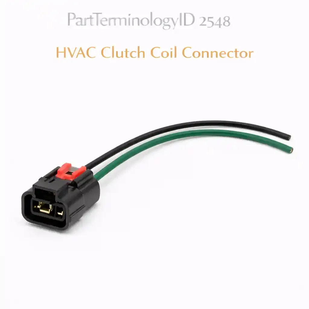
PartTerminologyID 2548, HVAC Clutch Coil Connector, is the wiring harness connector body that mates with the AC compressor clutch coil, providing the electrical interface between the vehicle's AC control circuit and the electromagnetic clutch coil terminals that engage and disengage the compressor when the AC system is commanded on. That definition covers the function correctly. It does not specify the terminal count, which is two terminals on virtually all applications where a dedicated supply wire and a dedicated ground wire both terminate at the connector, or one terminal on applications where the compressor clutch coil grounds through the compressor housing to the engine block and only the supply circuit terminates at the connector, the connector body housing series designation, the compressor model the connector is matched to, whether the connector includes an integrated flyback suppression diode across the supply and ground terminals to absorb the inductive voltage spike generated when the clutch coil is de-energized, the diode orientation within the connector body, the wire gauge of the supply and ground wires, the pigtail length, the connector body temperature rating for the under-hood location adjacent to the compressor body and belt drive system, and whether the listing covers the connector body only or a pigtail assembly with pre-installed terminals and wire. A listing under PartTerminologyID 2548 that provides vehicle year, make, and model without the compressor model designation, the terminal count, the diode inclusion status, and the wire gauge cannot be evaluated by any technician replacing a heat-melted, oil-contaminated, or broken HVAC clutch coil connector and confirming the replacement before accessing the compressor clutch coil terminals on the front face of the compressor.
For sellers, PartTerminologyID 2548 contains a specification argument that appears nowhere else in this connector series: the flyback suppression diode. The AC compressor clutch coil is an electromagnetic inductive load drawing 3 to 5 amperes of continuous current through a coil resistance of typically 3 to 5 ohms. Every time the AC control system commands the clutch to disengage, whether from a pressure switch cutout, a WOT relay cutout, or a driver switching the AC off, the magnetic field in the clutch coil collapses instantaneously. That collapsing field generates a reverse-polarity inductive voltage spike of 60 to 100 volts or higher on the supply and ground wires, lasting microseconds but sufficient to arc across relay contacts, stress PCM output drivers, and corrupt ECM digital signal lines that share ground paths with the clutch supply circuit. The flyback suppression diode, installed in reverse-bias across the two clutch supply terminals inside the connector body, conducts this reverse-polarity spike back through the coil as a circulating current and dissipates it as heat, preventing the spike from reaching the relay, the pressure switch, or the PCM. A replacement connector that omits the diode where the OEM connector included one does not prevent clutch engagement or create an immediately visible fault, it operates the clutch normally while leaving the relay contacts, the pressure switch, and the PCM input circuits unprotected from every subsequent clutch disengagement event.
For sellers, the listing under this PartTerminologyID is only useful if it specifies the compressor model as the primary fitment attribute, the terminal count, the diode inclusion status and orientation, the wire gauge, the connector body housing series, and the pigtail versus connector body only designation. Without those attributes, the listing either prevents engagement from the first installation through a terminal mismatch, or installs a connector that operates normally while quietly damaging the relay contacts and PCM on every clutch cycle.
What the HVAC Clutch Coil Connector Does
Delivering switching current to the electromagnetic clutch coil
The AC compressor clutch consists of a stationary electromagnetic coil mounted on the front face of the compressor body and a rotating pulley that is belt-driven continuously whenever the engine runs. When the clutch coil is energized, it generates a magnetic field that pulls the clutch plate against the rotating pulley face, coupling the compressor shaft to the belt drive and engaging refrigerant compression. When the coil is de-energized, the plate releases, the compressor shaft decouples, and the pulley continues spinning freely. The connector delivers the supply voltage to the coil terminal and, on two-terminal designs, provides the ground return path through a dedicated ground wire rather than relying solely on the compressor housing-to-engine-block ground path.
The clutch coil draws steady current throughout the engagement period. Unlike a sensor connector that carries milliampere-level signal currents, the HVAC clutch coil connector carries 3 to 5 amperes continuously at 12 to 14 volts during every AC-on condition. On vehicles where the AC compressor cycles on and off under thermostat or pressure switch control during a single drive cycle, potentially 20 to 40 clutch engagement and disengagement events per hour in stop-and-go city driving with the AC set to automatic temperature control, the connector's terminal contact surfaces and the diode inside the connector body both experience repeated current make-and-break events that accumulate degradation over the vehicle's service life.
Why the flyback suppression diode is inside the connector, not the relay or PCM
On post-1986 GM vehicles using Delphi Metri-Pack 150 connector housings at the compressor clutch, and on many Ford, Chrysler, Toyota, and Honda applications from the early 1990s onward, the flyback suppression diode is located at the compressor clutch connector rather than at the relay or PCM for a specific circuit design reason: placing the diode at the load, the clutch coil, ensures that the inductive spike is suppressed at its source, at the coil terminals, before it can propagate any distance along the harness wires. A diode at the relay or fuse box would allow the spike to travel the full harness length from the compressor to the relay before being suppressed, exposing the entire harness run to the reverse-polarity voltage for the spike's duration. Suppression at the connector limits the spike's propagation path to the distance between the connector and the coil terminals, which is typically zero on direct-mount connector designs and a few centimeters on pigtail designs.
The consequence of a missing or open diode at the connector is not immediate component destruction. The relay contacts that switch the clutch supply circuit experience increased arc erosion at every contact-open event. The arc that would be suppressed by the diode is instead absorbed by the relay contact faces, accelerating contact pitting and increasing contact resistance over time until the relay contacts fail to deliver full supply voltage to the clutch coil. The PCM output drivers and shared ground-circuit components experience the full reverse-polarity spike on every disengagement event. On vehicles with heavily multiplexed HVAC control systems where the clutch relay coil ground is managed by a PCM output, the inductive spike from a diode-less connector can produce intermittent PCM fault codes, most commonly P1660 fan circuit faults or spurious HVAC control module communication codes, that diagnostic scans cannot correlate to a clutch connector specification error.
The heat environment at the compressor clutch connector location
The AC compressor is mounted at the front of the engine, driven by the serpentine belt, and is surrounded by the accessory drive system components that generate the highest sustained ambient temperatures in the engine bay. The compressor body itself runs warm from refrigerant compression heat. The clutch coil, which is a wire-wound electromagnetic coil, generates resistive heat from the continuous 3-to-5-ampere current flow whenever the clutch is engaged. The connector body, seated directly on the coil terminal face, is exposed to both the coil's conducted heat and the radiated heat from the engine block and accessory drive components. On many transverse-engine front-wheel-drive vehicles, the compressor is mounted low in the engine bay on the firewall side, where exhaust heat from the manifold above adds to the thermal load.
The connector body must sustain continuous ambient temperatures of 100 to 125 degrees Celsius at the compressor mounting location without softening at the terminal cavities or allowing the terminal retention clips to deform and lose their grip on the clutch coil terminals. A connector body that softens at sustained operating temperature will allow the terminal cavities to widen, reducing the contact normal force at the terminal interface and increasing contact resistance. Increased contact resistance at 3 to 5 amperes of continuous current produces I²R heating at the contact interface, which accelerates softening and terminal deformation in a progressive feedback cycle that ends in a melted connector body and an open-circuit clutch coil supply.
Why the compressor model designation is the primary fitment attribute above vehicle application
The HVAC clutch coil connector is mated to the terminals on the compressor clutch coil, not to the vehicle's harness. This means the physical fitment, terminal gender, terminal pitch, connector body profile, locking mechanism, and orientation relative to the coil terminal face, is determined by the compressor model, not by the vehicle. The same vehicle may have been equipped with compressors from multiple manufacturers across its production run: a 2004 Chevrolet Silverado with 5.3L V8 may have left the factory with a Delphi Harrison V5, a Delphi Harrison V7, or a Sanden SD7H15 compressor depending on production date and production plant. The clutch coil connector terminal profile and housing geometry differ between these compressor families. A connector listed for the Silverado 5.3L by vehicle application alone cannot be confirmed correct without the compressor model designation, because the vehicle fitment range encompasses multiple compressor designs with different connector requirements.
On aftermarket replacement compressors, the connector requirement may differ from the OEM compressor even when the aftermarket compressor is described as a direct replacement. Many aftermarket compressors are assembled from components sourced from different suppliers than the OEM, and the clutch coil terminal geometry may use a different housing series than the OEM compressor's coil. A technician who sources a connector by vehicle year, make, and model for a vehicle equipped with an aftermarket replacement compressor may receive a connector matched to the OEM compressor housing that does not fit the aftermarket replacement coil terminal.
The Specifications That Determine Correct HVAC Clutch Coil Connector Fitment
Terminal count: one or two
Two terminals is the standard for virtually all post-1985 domestic and import applications: a supply terminal and a dedicated ground terminal. One terminal exists on some applications where the compressor housing provides the ground return path through the compressor mounting bolts to the engine block, with only the supply circuit terminating at the connector. The one-terminal design requires a reliable engine block ground at the compressor mounting points; corrosion at the compressor mounting bracket will produce a ground fault that presents identically to a supply fault and is frequently misdiagnosed as a failed clutch coil. State the terminal count. Do not allow vehicle application alone to resolve it.
Diode inclusion: with diode or without diode
State explicitly whether the connector body includes a flyback suppression diode across the supply and ground terminals, and if so, state the diode's orientation, cathode to the supply terminal (positive voltage side), anode to the ground terminal, because a reversed diode will short the supply circuit to ground on energization, blowing the AC fuse instantly. On GM applications using Delphi Metri-Pack 150 connectors from 1986 onward, the diode is a standard feature of the OEM clutch coil connector and is oriented with the cathode (banded end) toward the dark green supply wire and the anode toward the black ground wire. Replacing an OEM diode-equipped connector with a connector body only, or with a pigtail that omits the diode, leaves the relay contacts and PCM circuits unprotected on every subsequent clutch disengagement.
Compressor model designation
The primary fitment attribute. The terminal pitch, the connector body profile, the terminal gender, the locking tab geometry, and the wire exit direction are all defined at the compressor model level. Specify the compressor model family (examples: Delphi Harrison V5, Harrison V7, Sanden SD5, SD7H15, Denso 10PA, Denso 6SEU, Zexel, Nippondenso, Valeo TM series) in the fitment attributes, not just the vehicle application.
Wire gauge
18-gauge wire is standard for the single-terminal supply pigtail on one-wire designs. On two-terminal designs with dedicated supply and ground wires both carrying 3 to 5 amperes continuously, 16-gauge wire is specified on some OEM harnesses where the circuit design places a long pigtail run from the connector to the harness junction. Verify the OEM wire gauge before sourcing, because a 20-gauge pigtail on a 5-ampere continuous load will produce a 0.25 to 0.4 volt drop along a 12-inch pigtail at operating temperature, reducing the clutch coil supply voltage below the minimum engagement threshold at the clutch coil terminals when ambient temperature has already increased the coil winding resistance by 15 to 20 percent above its cold resistance.
Connector body housing series designation
On GM applications: Delphi Metri-Pack 150 is the dominant series from 1986 onward. On Ford applications: various AMP/TE Connectivity series depending on model year and compressor supplier. On Toyota and Honda applications: sumitomo or equivalent OEM housing series. The housing series determines the external body dimensions, the terminal pitch, the locking tab geometry, and the secondary lock or CPA (connector position assurance) mechanism. Two connectors with identical terminal counts and diode configurations may belong to different housing series and have different external profiles that prevent cross-fitment even though both are listed for the same compressor model.
Pigtail wire length
The pigtail must reach from the compressor clutch coil terminal face to the harness junction without tension on the connector body and without creating slack that can contact the belt drive or accessory drive components. On most domestic applications, 12 inches (305mm) of pigtail wire is standard for OEM-length replacement. On some compressor locations in transverse front-wheel-drive engine bays where the compressor is mounted low and the harness junction is routed away from the belt zone, 16 to 18 inches may be required. State the pigtail length in inches and millimeters.
Connector body temperature rating
Minimum 125 degrees Celsius continuous for compressor-mounted locations. Some connector body materials rated at only 85 or 105 degrees will soften progressively at the sustained temperatures generated by the combined compressor body heat, clutch coil resistive heat, and engine bay ambient in high-load conditions. The temperature rating of the connector body material must be confirmed for the specific compressor mounting location before sourcing a replacement.
Status in New Databases
PIES/PCdb: PartTerminologyID 2548, HVAC Clutch Coil Connector
PIES/PCdb 2.0: No change
Top Return Scenarios
Scenario 1: "Connector without diode installed in place of OEM diode-equipped connector, relay contacts failed within one season, intermittent P1660 ECM codes"
The listing specified an HVAC clutch coil connector by vehicle year, make, and model without stating the diode inclusion status. The vehicle is a 1998 GM truck whose OEM Delphi Metri-Pack 150 clutch coil connector includes a flyback suppression diode integrated into the connector body across the dark green supply wire and the black ground wire. The replacement connector is a Metri-Pack 150 two-terminal housing without a diode. The connector seated correctly, locked positively, and the AC system operated normally for the first driving season. Over the following summer, the AC compressor relay began exhibiting intermittent engagement failures. The relay contacts, which experienced unprotected inductive arcing on every clutch disengagement, pitted progressively until contact resistance at the relay output terminal increased to the point where voltage drop across the relay contacts reduced the clutch coil supply from 13.8 volts to 11.2 volts, preventing engagement in high-ambient-temperature conditions where the clutch coil winding resistance was elevated. Two relays and one PCM were replaced before the connector's missing diode was identified as the root cause.
Prevention language: "Diode included: [yes, with flyback suppression diode, cathode to supply terminal / no diode]. On this application, the OEM clutch coil connector includes a flyback suppression diode integrated into the connector body. The diode protects the AC compressor relay contacts and PCM output circuits from the inductive voltage spike generated when the clutch coil is de-energized. A replacement connector that omits the diode will not prevent clutch engagement but will allow unprotected inductive arcing at the relay contacts on every clutch disengagement event, accelerating relay contact erosion and producing intermittent PCM fault codes. Confirm whether this application requires a diode-equipped connector before ordering."
Scenario 2: "Diode installed reversed in replacement pigtail, AC fuse blown on first key-on, no clutch engagement"
The listing specified a diode-equipped HVAC clutch coil pigtail but did not state the diode orientation relative to the supply and ground terminals. The replacement pigtail included a diode wired with the cathode toward the ground terminal and the anode toward the supply terminal, the reverse of the correct orientation. In the reversed orientation, the diode is forward-biased when the AC control circuit applies 12 volts to the supply terminal, presenting a near-short circuit across the supply and ground wires. The AC compressor fuse blew within 2 seconds of the first AC-on command. A second pigtail sourced from the same listing was installed with the same reversed orientation, blowing the replacement fuse on first engagement. The technician sourced a third pigtail after identifying the diode reversal in the connector body under magnification.
Prevention language: "Diode orientation: cathode (banded end) to supply terminal (positive voltage side, dark green wire on GM Metri-Pack applications), anode to ground terminal (black wire). A reversed diode will short the supply circuit to ground on first AC engagement, blowing the fuse instantly. Before installing, verify diode orientation with a multimeter on the diode test function: the forward-bias reading (0.5 to 0.7 volts) should appear when the positive probe is on the supply terminal side and the negative probe is on the ground terminal side. If the forward-bias reading appears in the reverse orientation, the diode is installed backwards."
Scenario 3: "Connector body only sourced for heat-melted original, supply terminal cavity soft from sustained temperature at compressor mounting location, new connector body also softens within two summers"
The original HVAC clutch coil connector on a 2002 Honda Civic had melted at the terminal entry face from sustained heat at the compressor mounting location on the firewall side of the transverse engine bay. The buyer sourced a connector body only, transferred the original terminals and diode into the new housing, and restored the connection. The replacement connector body was sourced from a generic aftermarket pigtail listing that did not state the connector body temperature rating. The replacement body was rated for 85 degrees Celsius continuous. Over the following two driving seasons, the replacement body progressively softened at the terminal cavities, widening the terminal retention geometry and reducing the contact normal force at the terminal interface. The resulting increase in contact resistance at the supply terminal produced I²R heating that melted the cavity walls adjacent to the supply terminal. The AC operated intermittently during hot weather before failing completely as the terminal lost retention.
Prevention language: "Connector body temperature rating: [85°C / 105°C / 125°C continuous]. The compressor mounting location on this vehicle sustains ambient temperatures above 100°C during high-load operation. A connector body rated below 125°C continuous will soften progressively at the terminal cavity walls, reducing terminal retention force and increasing contact resistance under sustained thermal load. Source a connector body or pigtail assembly with a confirmed 125°C or higher continuous temperature rating for this mounting location. State the temperature rating in the listing."
Scenario 4: "OEM compressor replaced with aftermarket unit, OEM connector profile does not seat on aftermarket coil terminal face, 3mm gap between connector body and coil terminal housing"
The listing specified an HVAC clutch coil connector by vehicle year, make, and model as the primary fitment attribute. The vehicle's OEM Denso 10PA17C compressor was replaced with an aftermarket replacement compressor from a different supplier. The aftermarket replacement compressor's clutch coil uses a different terminal housing geometry than the Denso OEM, with a different external profile on the coil terminal block and a different locking tab engagement depth. The OEM-matched connector listed for this vehicle year, make, and model seated on the aftermarket coil's terminal pins but could not engage the locking tab because the connector body's latch recess did not align with the aftermarket coil housing's tab protrusion. The connector seated 3mm short of full engagement, leaving terminal contact depth at approximately 60 percent of designed engagement. The AC clutch engaged intermittently during vibration-free highway driving but disengaged on rough roads as vibration rocked the under-engaged connector across the terminal contact faces.
Prevention language: "Compressor model designation: [OEM compressor model / aftermarket compressor manufacturer and model]. The connector body profile and locking tab geometry are determined by the compressor clutch coil housing, not by the vehicle application. An aftermarket replacement compressor may use a different clutch coil housing geometry than the OEM compressor even when described as a direct vehicle replacement. Confirm the compressor manufacturer and model installed in the vehicle before ordering the clutch coil connector. If the vehicle has been fitted with an aftermarket compressor, identify the aftermarket compressor's coil terminal housing series and source a connector matched to that housing."
Scenario 5: "20-gauge pigtail wire installed on application requiring 16-gauge, voltage drop across pigtail at operating temperature prevents clutch engagement on hot days"
The listing specified an HVAC clutch coil pigtail without stating the wire gauge. The replacement pigtail uses 20-gauge wire. The OEM pigtail for this application uses 16-gauge wire on both the supply and ground runs, because the circuit design routes a 14-inch pigtail from the connector to the harness junction on a compressor mounted low in the engine bay where the harness cannot take a direct path to the junction. At operating temperature on a 100-degree Fahrenheit ambient day, the clutch coil winding resistance had increased from its cold value of 3.2 ohms to approximately 3.8 ohms. The 20-gauge supply wire's resistance of 0.08 ohms per foot produced a voltage drop of 0.13 volts over the 14-inch run at the 3.7-ampere coil current. Combined with the 0.13-volt drop on the 20-gauge ground wire and a 0.3-volt drop at the relay, the clutch coil received 12.84 volts rather than the 13.4-volt charging system output. At the elevated winding resistance, the coil current dropped to 3.38 amperes, reducing the clutch plate magnetic pull force below the minimum required for positive engagement against the return spring preload. The AC clutch slipped intermittently on engagement and failed to engage fully during extended idle in high ambient temperatures.
Prevention language: "Wire gauge: [16-gauge / 18-gauge / 20-gauge]. The pigtail wire gauge must match the OEM specification for this application. On this compressor mounting location, the 14-inch pigtail run carries 3.5 to 4.5 amperes of continuous current. A 20-gauge wire on this run produces a voltage drop that reduces clutch coil supply voltage by 0.25 volts or more at operating temperature when coil winding resistance is elevated by heat. The voltage reduction is sufficient to prevent full clutch engagement on hot days with high ambient temperature. Source a pigtail with wire gauge confirmed to match the OEM specification for this compressor and mounting location."
What to Include in the Listing
Core essentials
PartTerminologyID: 2548
Component: HVAC Clutch Coil Connector
Compressor model designation (mandatory, primary fitment attribute, state manufacturer and model family)
Terminal count: 1 or 2 (mandatory)
Circuit assignment: supply terminal and ground terminal with wire color callout (mandatory)
Diode included: yes or no (mandatory)
If yes: diode type (flyback suppression silicon diode), orientation (cathode to supply terminal), and diode rating in volts and amperes (mandatory)
Connector body housing series designation (mandatory)
Connector body temperature rating in degrees Celsius continuous (mandatory)
Wire gauge at supply and ground terminals (mandatory)
Pigtail wire length in inches and millimeters (mandatory)
Pigtail or connector body only (mandatory)
Wire insulation rating for under-hood heat and oil splash exposure (mandatory)
Lock type: primary latch only or primary latch with CPA (mandatory)
Quantity: 1
Fitment essentials
Compressor model designation as primary fitment attribute above vehicle year, make, and model
Vehicle year, make, model, submodel as secondary fitment attribute
Engine designation where compressor model differs by engine within the same vehicle
OEM vs. aftermarket compressor fitment note where the connector profile differs
Production date range where a compressor model transition exists within a vehicle model year
Dimensional essentials
Connector body overall length in mm
Connector body width in mm
Terminal pitch in mm
Pigtail length in mm
Wire exit angle: inline or right-angle
Image essentials
Connector from the terminal-entry face showing the two terminal cavities with supply and ground labeled, and the diode visible across the cavities if present
Connector from the wire exit side showing the pigtail with wire gauge callout and the diode orientation marked on the pigtail body
Diode shown separately with cathode band orientation labeled relative to supply and ground wires
Connector shown mated to the compressor clutch coil terminal face with the lock mechanism fully engaged
Heat-damaged original connector shown alongside undamaged replacement to illustrate the terminal cavity softening and terminal face melting pattern that characterizes the thermal failure mode at this location
Catalog Checklist for ACES/PIES Teams
PartTerminologyID = 2548
Require compressor model designation as primary fitment attribute (mandatory, vehicle application alone is insufficient)
Require terminal count (mandatory)
Require diode inclusion status (mandatory, this is the specification that protects relay contacts and PCM circuits; its omission produces no immediate symptom)
Require diode orientation if diode is included (mandatory, reversed diode blows fuse on first engagement)
Require wire gauge (mandatory, undersized wire on inductive load produces voltage-drop engagement failure at elevated ambient temperature)
Require connector body temperature rating (mandatory, below-spec body material softens at compressor mounting location, producing thermal runaway contact resistance)
Require pigtail length (mandatory)
Differentiate from HVAC compressor clutch (the clutch is the electromagnetic plate-and-pulley assembly that engages the compressor shaft; the connector is the harness interface to the clutch coil electrical terminals; a damaged connector does not require clutch replacement if the clutch coil winding resistance is confirmed within specification)
Differentiate from AC pressure switch connector: the pressure switch connector carries a low-current signal circuit to the PCM or control module; the clutch coil connector carries a high-current switching circuit to the electromagnetic clutch coil; the two connectors are in the same AC circuit but serve different components with different current requirements and different connector body specifications
Flag diode inclusion as mandatory: this is the invisible specification whose omission produces downstream relay and PCM damage that presents as unrelated electrical faults; no symptom at the clutch connector level indicates the diode is missing until relay contact erosion produces intermittent engagement failures months after installation
Flag compressor model as mandatory primary attribute: vehicle application alone does not resolve connector profile in vehicles equipped with aftermarket replacement compressors or in model years that span a compressor model transition
FAQ (Buyer Language)
Why does my AC clutch connector need a diode? The replacement I found doesn't have one.
The diode is a flyback suppression component that absorbs the inductive voltage spike generated by the clutch coil every time the AC is switched off. The clutch coil is an electromagnet, a coil of wire, and like any inductor, it stores energy in its magnetic field while energized. When that field collapses on disengagement, the stored energy generates a reverse-polarity voltage spike of 60 to 100 volts or higher that travels back through the harness toward the relay and PCM. The diode, installed backward across the supply and ground wires, conducts this spike as a circulating current back through the coil and dissipates it as heat before it reaches the relay or PCM. If your OEM connector had a diode and your replacement does not, the clutch will still work, but every clutch disengagement will arc the relay contacts and stress the PCM until one of them fails.
How do I check whether my original connector had a diode?
Unplug the original connector from the compressor and set your multimeter to the diode test function. Touch the positive probe to one wire and the negative probe to the other. If you get a forward-voltage reading of 0.5 to 0.7 volts in one direction and an open circuit when the probes are reversed, the connector contains a diode. If you get similar ohm readings in both directions, the connector does not contain a diode, you are reading only the clutch coil resistance through the connector. You can also visually inspect the connector body for a small rectangular or cylindrical component encapsulated in heat shrink or overmolded into the connector body near the wire exit.
Can I use a connector matched to a different compressor brand if the terminal pins look the same?
Not reliably. The terminal pins on the compressor clutch coil may look similar across different compressor families, but the connector body external profile, the locking tab geometry, the terminal pitch, and the engagement depth are defined by the compressor model, not by the terminal pin dimensions. Two connectors that appear to fit the same terminal pins but belong to different housing series will produce a connector that seats partially, locks incorrectly, or fails to maintain positive engagement under vibration. Confirm the compressor manufacturer and model on the compressor body label before sourcing the connector.
My compressor was replaced with an aftermarket unit. How do I find the right connector?
Locate the model designation on the aftermarket compressor's body, typically on a label on the compressor housing or stamped into the casting near the clutch face. Cross-reference the model designation to the clutch coil terminal housing series. If the aftermarket compressor does not have a visible model designation, measure the terminal face geometry: record the terminal pitch (center-to-center distance between the two coil terminals), the terminal pin diameter, and the connector body width at the coil terminal face. Provide those dimensions to the connector supplier to identify the housing series. Do not assume the aftermarket compressor's connector requirement matches the OEM compressor that was replaced, even if the compressor is described as a direct-fit replacement for your vehicle.
Cross-Sell Logic
AC Compressor Clutch: If the connector was heat-damaged to the point of terminal melting, the clutch coil terminals themselves may have experienced the same sustained heat that damaged the connector. Measure clutch coil resistance before reassembly: specification is typically 3 to 5 ohms. A reading below 2 ohms indicates a shorted coil winding. A reading above 5 ohms or an open circuit indicates a burned winding. Replace the coil or the clutch assembly if the resistance is out of specification.
AC Compressor Relay: If the original connector was missing a diode or had an open diode, the relay contacts have experienced unprotected inductive arcing on every clutch disengagement since the diode failed or went missing. Inspect the relay contacts or replace the relay at the same service event as the connector, because relay contact erosion from unprotected arcing produces intermittent engagement failures that will recur regardless of the new connector's diode status if the relay contacts are already pitted.
AC Pressure Switch: On cycling-clutch orifice tube systems where the low-side pressure switch controls clutch engagement frequency, a pressure switch whose contacts are borderline can produce rapid clutch cycling that accelerates connector terminal wear and diode degradation. Confirm pressure switch operation at the same service event as the connector replacement.
Compressor Ground Strap: On one-terminal connector applications where the ground return is through the compressor housing, a corroded or loose compressor mounting ground presents identically to a supply fault at the clutch coil connector. Inspect and clean the compressor mounting bolt contact surfaces and the ground strap if equipped.
Frame as: "The connector puts power to the coil. The diode protects the relay and PCM from the coil. The relay sends power when the PCM says to. All three are in the same circuit. A fault in any one of them sets the same symptom: AC doesn't engage."
Final Take for PartTerminologyID 2548
HVAC Clutch Coil Connector (PartTerminologyID 2548) is the connector PartTerminologyID in this series that carries the highest continuous current of any HVAC connector category, 3 to 5 amperes at 12 to 14 volts, continuously throughout every AC-on event, and is the only category where the connector body contains an active electronic component, the flyback suppression diode, whose omission produces no immediate symptom while progressively damaging a relay and potentially a PCM module on every subsequent clutch cycle. The thermal environment at the compressor clutch face is among the most demanding of any connector location in the powertrain bay: coil resistive heat, compressor body heat, engine bay radiated heat, and sustained accessory drive ambient temperatures combine to challenge connector body materials that are specified at 85 or 105 degrees Celsius rather than the 125 degrees Celsius minimum appropriate for this location.
The compressor model designation must be the primary fitment attribute above vehicle year, make, and model because the connector body profile is defined at the compressor clutch coil housing level. The diode inclusion status must be explicit because a diode-less replacement in a diode-required application produces relay and PCM damage that presents months after installation as an unrelated electrical fault. The diode orientation must be explicit because a reversed diode blows the AC fuse on the first engagement attempt. The wire gauge must be explicit because an undersized supply wire on a continuous 3-to-5-ampere inductive load produces a voltage-drop engagement failure at elevated ambient temperature that presents as a failed clutch coil rather than as a pigtail wire specification error.
State the compressor model. State the terminal count. State the diode inclusion status and orientation. State the wire gauge. State the connector body temperature rating. State the pigtail length. Those are the six attributes that determine whether the replacement connector restores full AC clutch function and protects the relay and PCM on every subsequent disengagement, or silently begins degrading the relay contacts and PCM output circuits from the moment the replacement is installed.