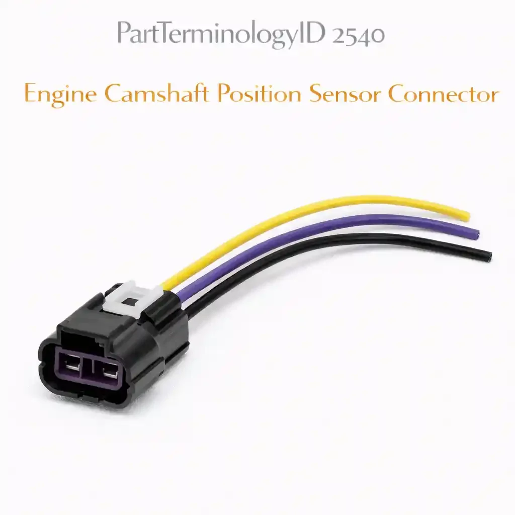
Engine Camshaft Position Sensor Connector (PartTerminologyID 2540): Why Sensor Type, Terminal Count, Oil Seal Proximity, and Ignition Interference Routing Prevent Timing and VVT Faults
Written by Arthur Simitian | PartsAdvisory
PartTerminologyID 2540, Engine Camshaft Position Sensor Connector, is the wiring harness connector body that mates with the camshaft position sensor, providing the electrical interface between the vehicle's engine management harness and the sensor terminals that carry the reference voltage supply, the signal ground, and the camshaft position signal output to the powertrain control module. That definition covers the function correctly. It does not specify the terminal count, which is two terminals for a variable reluctance sensor that generates its own AC signal and requires no external power supply, or three terminals for a Hall effect sensor that requires a 5-volt reference supply, a dedicated signal ground, and a separate digital signal output wire, the connector body housing series designation, the sensor type compatibility, whether the connector is designed for a variable reluctance sensor with a two-terminal sine-wave output interface or a Hall effect sensor with a three-terminal square-wave digital output interface, the camshaft position sensor part number the connector is matched to, the seal type and whether the connector uses individual wire seals rated for oil splash exposure at the sensor's mounting location on or near the cylinder head, the connector body temperature rating for proximity to the cylinder head and valve cover surfaces, the ignition interference routing provisions, whether the connector body and its wire exit geometry allow the signal wire to be routed away from secondary ignition components that produce electromagnetic interference capable of corrupting the low-voltage camshaft position signal, the bank and camshaft designation for multi-camshaft engines where separate connectors are used for intake and exhaust camshaft sensors on each bank, or whether the listing covers the connector body only or a pigtail assembly with pre-installed terminals and wire. A listing under PartTerminologyID 2540 that provides vehicle year, make, and model without the sensor type, the terminal count, the camshaft and bank designation on multi-camshaft engines, and the connector housing designation cannot be evaluated by any technician who has a corroded, cracked, or oil-contaminated camshaft position sensor connector and is confirming the replacement before accessing the sensor at its cylinder head or timing cover mounting location.
For sellers, PartTerminologyID 2540 occupies the intersection of three specification arguments that have been developed separately in diagnostic literature but must be resolved simultaneously at the connector level: the sensor type argument that differentiates two-terminal variable reluctance connectors from three-terminal Hall effect connectors, the oil contamination argument that applies to connectors mounted on or immediately adjacent to camshaft position sensors whose mounting bosses are in close proximity to valve cover gaskets, camshaft oil seals, and VVT oil control solenoid assemblies that are known oil migration pathways, and the ignition interference routing argument that applies to the signal wire exit geometry of connectors mounted on engines where the camshaft position sensor signal wire must be routed near ignition coil-on-plug connectors, high-tension ignition wires, or spark plug boots. A connector that mismatches sensor type will either leave the 5-volt reference terminal unconnected on a Hall effect sensor or place a reference voltage on a terminal that a variable reluctance sensor has no circuit to receive, producing a no-signal condition or a corrupted signal that sets P0340 from the first start. A connector with inadequate sealing mounted where oil migration from a weeping valve cover gasket can reach the connector face will contaminate the terminal contact surfaces with oil that increases contact resistance progressively until the camshaft signal drops below the PCM's detection threshold. A connector with a wire exit geometry that routes the signal wire parallel to and within 20mm of an ignition coil connector will allow secondary ignition system switching transients to induce voltage spikes on the signal wire that the PCM interprets as false camshaft position pulses, setting P0341 range and performance codes without any physical connector damage.
The additional complexity specific to PartTerminologyID 2540 compared to the HVAC blower motor resistor connector (2536) is the multi-axis specification argument. The blower motor resistor connector has one dominant failure mode: the undersized supply terminal current rating. The camshaft position sensor connector has three concurrent failure modes - sensor type mismatch, oil contamination at the terminal faces, and ignition interference on the signal wire - any one of which produces fault codes that present identically to a failed camshaft position sensor. A technician who replaces the sensor without addressing the connector specification that caused the original failure will replace the sensor into the same fault condition, setting the same code within days or miles and attributing the repeat failure to a defective aftermarket sensor rather than to an unresolved connector specification error.
For sellers, the listing under this PartTerminologyID is only useful if it specifies the sensor type, the terminal count, the camshaft and bank designation on multi-camshaft engines, the connector housing designation, the seal type and oil resistance rating, the connector body temperature rating, and whether the listing is a connector body only or a pigtail assembly. Without those attributes, the listing cannot prevent the sensor type mismatch that produces a no-signal condition from the first installation, the oil contamination failure that produces progressive signal degradation, or the ignition interference routing error that produces intermittent false timing signals that the PCM cannot distinguish from valid camshaft position data.
What the Engine Camshaft Position Sensor Connector Does
Carrying the 5-volt reference supply and signal ground for Hall effect sensors
On all Hall effect camshaft position sensors, which are the dominant type on post-1996 OBD-II vehicles, the connector carries three circuits: the 5-volt reference supply from the PCM that powers the sensor's internal Hall effect switching circuit, the signal ground that provides the return path for both the reference supply current and the signal output current, and the signal output wire that carries the digital square-wave signal generated by the sensor as the camshaft reluctor teeth pass through the sensor's magnetic field window. The 5-volt reference supply and the signal ground must both be present and within specification at the connector terminals before the sensor can generate any output signal. A connector that produces even 0.3 volts of voltage drop on the 5-volt reference terminal from elevated contact resistance will reduce the supply voltage at the sensor's input below the minimum threshold required for the Hall effect switching circuit to operate reliably at all engine speeds and temperatures, causing intermittent signal loss that worsens as contact resistance increases with temperature cycling.
On variable reluctance camshaft position sensors, which are found on pre-OBD-II vehicles and on some diesel and industrial engine applications, the connector carries only two circuits: the two ends of the sensor's inductive coil, which generates an AC sine-wave signal whose amplitude and frequency both increase with camshaft rotational speed. The variable reluctance sensor requires no external power supply because its signal is derived entirely from the changing magnetic field as the reluctor teeth pass the sensor tip. A connector for a variable reluctance sensor has two terminals with no polarity assignment in some designs, though most OEM connectors key the terminal positions to prevent reversal. Installing a three-terminal Hall effect connector on a two-terminal variable reluctance sensor leaves one terminal cavity with no mating pin, which is a physical mismatch that prevents the connector from seating fully if the unused cavity is positioned to interfere with the sensor body.
Carrying the camshaft position signal for VVT system phasing feedback
On engines with variable valve timing, the camshaft position signal carries information that the PCM uses for two distinct functions: first, the standard cylinder identification function that tells the PCM which cylinder is approaching top dead center on the compression stroke to sequence fuel injection and spark timing, and second, the VVT phasing feedback function that tells the PCM the actual angular position of the camshaft relative to the crankshaft so it can compare the actual cam phaser position to the commanded position and adjust the VVT oil control solenoid duty cycle to eliminate the error. The VVT phasing feedback function requires the connector's signal terminal to maintain contact resistance low enough that the digital signal edge timing is not degraded by RC time constant effects from contact resistance and wire capacitance. A connector with 5 ohms of contact resistance at the signal terminal on a VVT feedback circuit with 500 picofarads of wire capacitance will produce a time constant of 2.5 nanoseconds, which is negligible at idle but becomes relevant on engines where the PCM calculates VVT phasing from individual tooth timing at high camshaft speeds. On high-tooth-count reluctor wheels with 24 or more teeth per revolution, the tooth period at 6,000 RPM camshaft speed is approximately 1.25 milliseconds, and signal edge timing errors of even 50 microseconds can produce VVT phasing errors of approximately 1.5 degrees of cam angle that the PCM interprets as a VVT control error.
Why the camshaft position sensor connector is a high-temperature and oil-contamination-risk component
The camshaft position sensor is mounted at or near the cylinder head on virtually all overhead cam engine designs, placing the connector in direct proximity to the cylinder head casting, the valve cover, and the camshaft oil seals. Cylinder head surface temperatures at the sensor mounting boss can reach 120 to 150 degrees Celsius during sustained high-load operation, and the connector body must withstand this continuous ambient without softening at the terminal cavities. The connector is also within oil migration range of several potential leak sources: the valve cover gasket immediately above the sensor mounting area on many DOHC engines, the front and rear camshaft oil seals whose deterioration allows oil to migrate along the camshaft into the sensor mounting boss, and on VVT-equipped engines the oil control solenoid O-rings that, when they weep, allow pressurized oil to track along the solenoid body toward the sensor connector area.
Oil contamination at the connector terminal faces is among the most common causes of camshaft position sensor connector failure identified in diagnostic literature. Oil that enters the connector face wicks between the terminal contact surfaces by capillary action and deposits a thin insulating film that increases contact resistance progressively over time. The contamination does not produce an immediate open circuit; it produces a gradual resistance increase that first causes the 5-volt reference voltage at the Hall effect sensor to drop marginally, reducing signal amplitude, then causes the signal output voltage swing to decrease below the PCM's detection threshold at elevated temperatures when contact resistance is at its maximum, and finally produces an intermittent no-signal condition that sets P0340 under conditions that a visual inspection of the connector cannot explain because the oil contamination is at the terminal interface surfaces inside the connector body rather than on the exterior.
Pigtail assembly for oil-contaminated or thermally cracked connector replacement
When the camshaft position sensor connector has been oil-contaminated at the terminal faces or has developed body cracks from sustained thermal cycling at the cylinder head mounting location, the harness wires immediately behind the connector may also show oil absorption into the wire insulation at the connector entry, or insulation brittleness from repeated heating and cooling cycles. A pigtail assembly that includes 200 to 300mm of new wire allows the technician to cut the harness behind the oil-affected or heat-affected zone and splice the pigtail to confirmed undamaged wire. On three-terminal Hall effect sensor pigtails, the wire gauge at each terminal position is typically 20 to 22 AWG for the signal wire and the ground, and 20 AWG for the reference supply, because the signal circuit carries only microamp-level currents and the reference supply carries only the sensor's quiescent current, which is typically 5 to 15 milliamperes. The pigtail wire gauge must match the original harness wire gauge to maintain the impedance characteristics of the signal circuit.
The Specifications That Determine Correct Camshaft Position Sensor Connector Fitment
Sensor type: variable reluctance or Hall effect
The single most consequential specification. Variable reluctance sensors use a two-terminal connector with no polarity-critical power supply circuit. Hall effect sensors use a three-terminal connector with a polarity-critical 5-volt reference supply at a defined terminal position. These are not interchangeable. A two-terminal connector on a three-terminal Hall effect sensor leaves the 5-volt reference terminal unmated. A three-terminal connector on a two-terminal variable reluctance sensor has no mating pin for the third terminal cavity and will not seat to its designed engagement depth if the cavity geometry conflicts with the sensor body. State the sensor type explicitly in the listing. Do not allow vehicle year, make, and model alone to resolve this attribute, because the same vehicle may have been produced with both sensor types in different model years, different engine variants, or different market specifications.
Terminal count
Two for variable reluctance. Three for Hall effect. On some engines with separate intake and exhaust camshaft sensors sharing a single harness branch, the connector may carry six terminals in a single housing serving both sensors. State the count and the circuit assignment at each terminal position.
Camshaft and bank designation for multi-camshaft engines
On inline four-cylinder DOHC engines with separate intake and exhaust camshaft sensors, the intake and exhaust sensors may use identical connector bodies but different pigtail wire lengths due to their different locations on the cylinder head. On V6 and V8 DOHC engines, four separate connectors are required: intake bank 1, exhaust bank 1, intake bank 2, exhaust bank 2. The connector for bank 1 exhaust is physically adjacent to the secondary ignition components for cylinder 1 on most V-type engine layouts, making its ignition interference routing provisions more critical than those for the bank 2 sensors on the opposite side of the engine. State the camshaft designation and bank designation explicitly for any engine with more than one camshaft position sensor.
Connector body housing series designation
The primary fitment attribute at the connector body level. Determines the terminal pitch, the connector body external profile, the lock mechanism, and the mating sensor terminal gender. Two connectors with identical terminal counts may have different housing series designations and different external profiles that prevent cross-fitment even though both are listed for the same sensor type.
Seal type and oil resistance rating
Individual wire seals with body-side seal, with the seal material rated for continuous oil exposure at the connector installation temperature. On sensors mounted at locations with confirmed oil migration risk from valve cover gaskets or camshaft seals, specify a seal rated for oil splash immersion rather than oil vapor only. The body-side seal must maintain its radial sealing force against the sensor body at the maximum operating temperature of the connector location without compression set reducing the sealing force below the minimum required to exclude oil from the terminal cavity area.
Connector body temperature rating
In degrees Celsius continuous ambient at the connector installation location. For sensors mounted directly on the cylinder head casting, specify a minimum of 125 degrees Celsius continuous. For sensors mounted on the timing cover at a location with less direct contact with the cylinder head casting, 105 degrees Celsius may be sufficient, but the installation temperature must be verified against the specific engine and sensor location.
Ignition interference routing provisions
Wire exit direction and the geometry of the connector body's wire exit strain relief must allow the signal wire to be routed away from secondary ignition components. On engines where the sensor location is within 50mm of an ignition coil-on-plug connector or within 100mm of a high-tension ignition wire, specify a connector body with a right-angle wire exit that allows the signal wire to route away from the ignition interference source rather than parallel to it. State the wire entry direction as part of the listing.
Pigtail or connector body only
State explicitly. For pigtail assemblies, state the wire length and gauge at each terminal position. For three-terminal Hall effect sensor pigtails, call out the signal wire gauge and the reference supply wire gauge separately because the signal wire routing requirements differ from those of the supply wire.
Status in New Databases
PIES/PCdb: PartTerminologyID 2540, Engine Camshaft Position Sensor Connector
PIES 8.0 / PCdb 2.0: No change
Top Return Scenarios
Scenario 1: "Three-terminal Hall effect connector installed on two-terminal variable reluctance sensor, connector would not seat fully, P0340 no-signal from first crank"
The listing specified a camshaft position sensor connector by vehicle year, make, and model without stating the sensor type. The vehicle has a two-terminal variable reluctance camshaft position sensor, which was used on this engine family through the 2001 model year before the transition to Hall effect sensors in 2002. The listing's vehicle fitment range spans both sides of this transition. The replacement connector is a three-terminal Hall effect housing. The third terminal cavity on the connector body conflicts with a locating boss on the two-terminal variable reluctance sensor body, preventing the connector from seating to its designed engagement depth. The primary latch engaged at a partial-engagement position that left the connector 3mm short of full seat. The terminal contact at the two matched positions was intermittent from partial engagement. The engine set P0340 on the first crank and would not sustain idle because the camshaft signal was absent at the PCM.
Prevention language: "Sensor type: [variable reluctance, 2-terminal / Hall effect, 3-terminal]. The sensor type determines the terminal count and the connector housing profile. Variable reluctance sensors use a 2-terminal connector. Hall effect sensors use a 3-terminal connector with a 5V reference supply terminal. These two connector types are not interchangeable. A 3-terminal Hall effect connector will not seat fully on a 2-terminal variable reluctance sensor. Verify the sensor type on the original connector before ordering. The vehicle application range for this listing spans a sensor type transition; confirm the sensor type for your specific production date."
Scenario 2: "Oil contamination at terminal faces from weeping valve cover gasket, progressive P0340 intermittent fault over 14 months"
The listing specified a camshaft position sensor connector by vehicle year, make, and model without stating the seal type or oil resistance rating. The replacement connector uses foam perimeter seals rated for oil vapor only. The vehicle has a known valve cover gasket weep at the rear of the left cylinder head on this engine, which channels oil along the head casting toward the intake camshaft position sensor mounting boss. Over 14 months, oil migrated through the foam seal perimeter and into the connector body, depositing a film on the terminal contact faces at the 5-volt reference terminal and the signal ground terminal. The contact resistance at the reference terminal increased from an initial measured value of 0.04 ohms to 1.2 ohms. The voltage drop across the contaminated reference terminal reduced the 5-volt reference at the sensor input to 4.4 volts at operating temperature. The sensor produced an intermittent signal that dropped out during hot-soak restarts, setting P0340 and causing extended crank times. Two camshaft position sensors were replaced before the connector was identified as the fault source.
Prevention language: "Seal type: [individual wire seals with body-side seal, oil-immersion-rated / foam perimeter seal, oil-vapor-rated]. The seal type must be appropriate for the oil contamination exposure at the camshaft position sensor mounting location. On this engine, the valve cover gasket at the rear of the left cylinder head is a known oil migration pathway to the intake camshaft sensor connector location. Specify a connector with individual wire seals and a body-side seal rated for oil splash or oil immersion exposure. A foam perimeter seal or an unsealed connector at this location will allow oil to reach the terminal contact surfaces and produce progressive contact resistance increase that presents as an intermittent camshaft sensor fault."
Scenario 3: "Signal wire routed parallel to ignition coil-on-plug connectors, ignition transients induced on signal wire, P0341 range and performance fault at warm idle"
The listing specified a camshaft position sensor connector without stating the wire exit direction. The replacement connector has an inline wire exit, which routes the pigtail wires along the valve cover surface and parallel to the bank 1 ignition coil-on-plug connectors. The signal wire runs at approximately 15mm separation from the ignition coil primary wiring for a distance of 80mm before reaching the harness bundle. At warm idle, the secondary ignition switching transients from the ignition coils induced voltage spikes of 0.3 to 0.8 volts on the camshaft position signal wire. The PCM interpreted some of these induced spikes as false camshaft position pulses that arrived out of sequence relative to the crankshaft position signal, setting P0341 range and performance fault code. The fault code set only at warm idle, not during cold start or acceleration, because the ignition dwell timing at that condition aligned with the signal wire's coupling frequency.
Prevention language: "Wire exit direction: [inline / right-angle]. On this engine, the camshaft position sensor connector signal wire must be routed away from the bank 1 ignition coil-on-plug connectors. A right-angle wire exit connector allows the signal wire to route away from the ignition coils immediately at the connector exit. An inline wire exit connector routes the signal wire parallel to the ignition coil primary wiring if the natural harness routing is followed. Ignition switching transients induced on the signal wire from parallel routing proximity below 50mm will produce P0341 range and performance fault codes at conditions where the inducing transients align with the signal wire's coupling characteristics."
Scenario 4: "Connector body only installed, original harness signal wire insulation oil-soaked at connector entry, oil absorption continues into new connector through splice point, contamination repeats within 8 months"
The original camshaft position sensor connector was oil-contaminated and the buyer sourced a connector body only. The harness signal wire at the connector entry showed light oil absorption into the insulation jacket for approximately 30mm behind the original connector, evident from the wire's reduced flexibility and slightly translucent insulation appearance in that section. The technician spliced the new connector body terminals to the original harness wires 10mm behind the old connector. Within 8 months, oil had wicked from the oil-absorbed section of the original harness wire through the splice joint and into the terminal area of the new connector body, reproducing the contact resistance contamination at the signal terminal. The PCM set P0340 again and the technician replaced the camshaft position sensor for the second time before inspecting the connector.
Prevention language: "Listing type: [connector body only / pigtail assembly with [X]mm of new wire]. If the original connector shows oil contamination, inspect the harness wires at the connector entry for oil absorption into the insulation jacket - indicated by reduced wire flexibility, translucent insulation, or an oily film on the insulation exterior - before sourcing a connector body only. Oil absorption in the insulation jacket will continue to wick through splice joints into a new connector body. Source a pigtail assembly long enough to place the splice in confirmed dry harness wire beyond the oil-affected section of the original harness."
Scenario 5: "Wrong bank connector installed on DOHC V6, pigtail wire too short to reach exhaust bank 2 sensor without tension on harness, connector partially unseated under vibration, P0345 intermittent"
The listing specified a camshaft position sensor connector for a DOHC V6 engine without distinguishing between the four sensor positions: intake bank 1, exhaust bank 1, intake bank 2, exhaust bank 2. The replacement pigtail is designed for the intake bank 1 sensor position and includes 180mm of pigtail wire. The buyer's failed connector is the exhaust bank 2 sensor, located 120mm farther from the harness junction than the intake bank 1 sensor. The 180mm pigtail reaches the exhaust bank 2 sensor with 35mm of slack remaining after splicing, insufficient to allow the harness to route through its original retaining clips without placing tension on the splice joint and connector body. Under engine vibration, the tension from the short pigtail worked the primary latch loose at 9,000 miles, producing intermittent terminal contact that set P0345 bank 2 camshaft sensor circuit malfunction.
Prevention language: "Camshaft position: [intake bank 1 / exhaust bank 1 / intake bank 2 / exhaust bank 2]. On DOHC V6 and V8 engines with separate connectors for each camshaft position sensor, the pigtail wire length is specific to the sensor position because the distance from the harness junction to each sensor location differs. A pigtail designed for the intake bank 1 sensor position will be too short to reach the exhaust bank 2 sensor position without tension on the splice joint and connector body. Identify the specific camshaft position designation of the failed connector before ordering."
What to Include in the Listing
Core essentials
PartTerminologyID: 2540
Component: Engine Camshaft Position Sensor Connector
Sensor type: variable reluctance (2-terminal) or Hall effect (3-terminal) (mandatory, primary specification attribute)
Terminal count (mandatory)
Circuit assignment at each terminal position: reference supply, signal ground, signal output for Hall effect; coil terminal A and coil terminal B for variable reluctance (mandatory)
Camshaft and bank designation: intake/exhaust, bank 1/bank 2 on multi-camshaft engines (mandatory)
Camshaft position sensor part number or designation (mandatory, primary fitment attribute)
Connector body housing series designation (mandatory)
Seal type: individual wire seals with body-side seal oil-immersion-rated; foam perimeter seal; or unsealed (mandatory)
Connector body temperature rating in degrees Celsius (mandatory)
Wire exit direction: inline or right-angle (mandatory)
Lock type: friction, primary latch, or primary with CPA (mandatory)
Mating sensor terminal gender and pitch (mandatory)
Pigtail or connector body only (mandatory)
Pigtail wire length in mm and wire gauge per terminal position, with signal wire gauge and routing notes called out separately (mandatory)
Quantity: 1
Fitment essentials
Year/make/model/submodel
Engine designation (mandatory - sensor type and connector housing frequently differ between engine variants sharing the same vehicle application)
Sensor type as primary specification attribute above vehicle application
Camshaft designation as secondary fitment attribute on multi-camshaft engines
Production date range where a sensor type transition exists within the vehicle model year
Dimensional essentials
Connector body overall length in mm
Connector body width in mm
Terminal pitch in mm
Terminal cavity depth in mm
Wire exit angle in degrees for right-angle connectors
Image essentials
Connector from the mating face showing terminal count and cavity arrangement with each position labeled by circuit assignment
Connector from the wire exit side showing seal type, wire exit direction, and lock mechanism
Two-terminal and three-terminal connectors shown side by side where both types exist in the vehicle application range, with sensor type label on each
Pigtail assembly shown full length with wire gauge, length, and signal wire routing callout
Oil-contaminated original connector shown alongside undamaged replacement to illustrate the terminal face contamination pattern and the oil absorption in the harness wire insulation
Catalog Checklist for ACES/PIES Teams
PartTerminologyID = 2540
Require sensor type (variable reluctance or Hall effect) as mandatory primary specification attribute
Require terminal count (mandatory)
Require circuit assignment at each terminal position (mandatory)
Require camshaft and bank designation on multi-camshaft engines (mandatory)
Require camshaft position sensor part number or designation as primary fitment attribute (mandatory)
Require seal type and oil resistance rating (mandatory)
Require connector body temperature rating (mandatory)
Require wire exit direction (mandatory)
Require pigtail versus connector body only designation (mandatory)
Differentiate from camshaft position sensor: the sensor is the electromechanical transducer that reads the reluctor wheel; the connector is the harness interface to the sensor's electrical terminals; a contaminated connector does not require sensor replacement if the sensor body is confirmed undamaged; the connector and the sensor are separate line items under separate PartTerminologyIDs
Differentiate from crankshaft position sensor connector: the camshaft connector interfaces the harness to the sensor that reads the camshaft reluctor wheel; the crankshaft connector interfaces the harness to the sensor that reads the crankshaft reluctor wheel; the two sensors use similar connector housings on many applications but serve different PCM input circuits with different fault code ranges (P0335-P0339 for crankshaft, P0340-P0349 for camshaft)
Differentiate from VVT oil control solenoid connector: the VVT solenoid connector carries the command signal to the solenoid; the camshaft position sensor connector carries the feedback signal from the position sensor; VVT phasing fault codes (P0011-P0019) can result from either connector fault
Flag sensor type as mandatory: this is the specification that prevents the most immediate fitment error - a type mismatch produces a no-start condition from the first crank
Flag seal type as mandatory: oil contamination at terminal faces is identified in diagnostic literature as one of the most common causes of camshaft sensor circuit codes; an inadequately sealed connector in an oil-migration-risk location fails progressively and presents as a sensor fault
Flag wire exit direction as mandatory: signal wire routing relative to secondary ignition components is a known source of P0341 range and performance codes; the wire exit direction determines whether the signal wire can be routed away from ignition interference sources at the connector exit
FAQ (Buyer Language)
How do I determine whether my camshaft position sensor uses a Hall effect or variable reluctance connector?
Count the terminals on the original connector. Two terminals indicate a variable reluctance sensor. Three terminals indicate a Hall effect sensor. If the original connector has already been destroyed, identify the camshaft position sensor part number from the sensor body and cross-reference it to confirm the sensor type. As a general rule, virtually all OBD-II equipped vehicles built after 1996 use Hall effect camshaft position sensors with three-terminal connectors. Variable reluctance camshaft position sensors are more common on pre-OBD-II applications and on some diesel engines. If the vehicle is a 1996 or later domestic or European model with sequential fuel injection, the camshaft sensor is almost certainly a Hall effect type with a three-terminal connector.
My camshaft position sensor connector shows oil inside. Does that mean the sensor failed?
Not necessarily. Oil inside the connector is a connector-level contamination event, not a sensor failure. Before replacing the sensor, clean the connector terminals with electrical contact cleaner, allow the connector and sensor terminals to dry completely, apply dielectric grease to the terminal contact faces to displace any residual moisture, and reconnect. Clear the fault code and test for recurrence. If the fault code does not return, the sensor itself was not at fault. If the fault code returns, assess whether the sensor body has been damaged by oil intrusion through the sensor tip. Also identify and repair the oil leak source - valve cover gasket, camshaft seal, or VVT solenoid O-ring - before installing a replacement connector. Installing a new connector without addressing the oil leak source will reproduce the contamination failure on the replacement.
Can a camshaft position sensor connector fault set VVT fault codes instead of camshaft circuit fault codes?
Yes, and this is the diagnostic complexity that makes PartTerminologyID 2540 more consequential than its sensor connector category suggests. On VVT-equipped engines, the camshaft position signal is used by the PCM both for basic cylinder identification and for real-time feedback on cam phaser angular position. A connector fault that degrades signal quality without producing a complete no-signal condition can cause the VVT phasing feedback loop to report cam phaser position errors and set P0011 through P0019 variable valve timing performance codes rather than P0340 through P0349 camshaft sensor circuit codes. A technician who responds to P0011 by replacing the cam phaser or the VVT oil control solenoid without inspecting the camshaft position sensor connector will replace the wrong component. Inspect the connector before attributing a VVT phasing fault to the cam phaser or solenoid.
What is the difference between the camshaft position sensor connector and the crankshaft position sensor connector?
The camshaft position sensor connector interfaces the harness to the sensor that reads the camshaft reluctor wheel, which provides the PCM with cylinder identification and, on VVT engines, cam phaser position feedback. The crankshaft position sensor connector interfaces the harness to the sensor that reads the crankshaft reluctor wheel, which provides the PCM with engine speed and crankshaft angular position. Faults in the camshaft connector set P0340 through P0349 codes. Faults in the crankshaft connector set P0335 through P0339 codes. The two sensors use similar connector housings on many applications and aftermarket catalog listings sometimes cross-populate the two PartTerminologyIDs. Confirm the sensor designation before ordering using the mounting location: camshaft sensors are mounted at the cylinder head or timing cover adjacent to the camshaft; crankshaft sensors are mounted at the engine block adjacent to the crankshaft pulley, harmonic balancer, or flywheel.
Cross-Sell Logic
Camshaft Position Sensor: If the connector oil contamination was caused by a failed camshaft oil seal that allowed oil to migrate into the sensor mounting bore, the sensor body itself may have oil inside its housing through the sensor tip. Confirm sensor output signal quality with an oscilloscope before relying on connector replacement alone when oil contamination is the failure mode.
Valve Cover Gasket: The valve cover gasket is the most common oil migration source to camshaft position sensor connector locations on overhead cam engines. Recommend inspection and replacement at the same service event to prevent recurrence.
VVT Oil Control Solenoid: On VVT engines, the oil control solenoid O-rings are in close proximity to the camshaft sensor connector on most DOHC engine layouts. A weeping solenoid O-ring produces the same oil migration pathway as a valve cover gasket failure. Inspect the solenoid O-ring condition at the same service event.
Camshaft Oil Seal: Camshaft front and rear oil seals that allow oil to migrate along the camshaft toward the sensor mounting boss are a direct contamination pathway. Inspect the camshaft seals if the connector contamination pattern shows oil entry from the sensor tip direction rather than from above.
Dielectric Grease: For connector body only replacements where the harness wires are confirmed undamaged, dielectric grease applied to the terminal contact faces at installation displaces moisture and oil vapor from the contact interface and provides a first line of defense against contamination-induced contact resistance increase.
Frame as "the camshaft sensor tells the PCM where the camshaft is. The connector tells the sensor it has power and a path for its signal. The oil seal keeps oil away from both. All three are inspected at the same service event because failure in any one of them sets the same fault code."
Final Take for PartTerminologyID 2540
Engine Camshaft Position Sensor Connector (PartTerminologyID 2540) is the connector PartTerminologyID in this series where three independent specification attributes each individually produce fault codes that present identically to a failed camshaft position sensor: the sensor type mismatch that produces a no-signal condition from the first installation, the inadequate seal specification that produces progressive oil contamination at the terminal faces over months of operation, and the incorrect wire exit direction that routes the signal wire into the electromagnetic field of the secondary ignition system and produces false timing pulses that the PCM cannot distinguish from valid camshaft position data. No other connector PartTerminologyID in this series has three concurrent invisible failure modes, each of which produces a specific diagnostic trouble code - P0340 for no-signal, P0340 intermittent for oil contamination, P0341 for ignition interference - without any visible damage to the connector body or harness that a technician inspecting the replacement installation would detect.
The consequence of each failure mode is proportionally severe. The sensor type mismatch produces a no-start or no-idle condition from the first crank after connector installation. The oil contamination failure produces progressive camshaft signal degradation that eventually prevents hot-soak restarts, stranding the vehicle and prompting repeated camshaft sensor replacements before the connector is identified as the fault source. The ignition interference routing error produces intermittent VVT phasing faults and misfires at specific engine speed and temperature conditions that cannot be reproduced on demand and cannot be diagnosed without understanding the signal wire routing geometry relative to the ignition coil mounting pattern.
State the sensor type in the primary specification attribute position. State the terminal count. State the circuit assignment at each position. State the camshaft and bank designation on multi-camshaft engines. State the seal type and its oil resistance rating. State the connector body temperature rating. State the wire exit direction. State the pigtail versus connector body designation. Include the sensor type cross-reference note for vehicle applications that span a sensor type transition. Include the oil contamination inspection note for pigtail versus connector body selection. Include the signal wire routing note for engines where the sensor location is within interference distance of the secondary ignition system. That is the same listing strategy as every other PartTerminologyID in this series, applied to a component where three specification attributes - not one or two - determine whether the replacement restores full engine management function or silently reproduces the fault code in a pattern that consumes diagnostic time and replacement sensors before the connector specification is identified as the root cause.