HVAC Blower Motor Resistor Connector (PartTerminologyID 2536): Why Terminal Count, Current Rating, and Resistor Pack Variant Prevent Blower Control Faults
Written by Arthur Simitian | PartsAdvisory
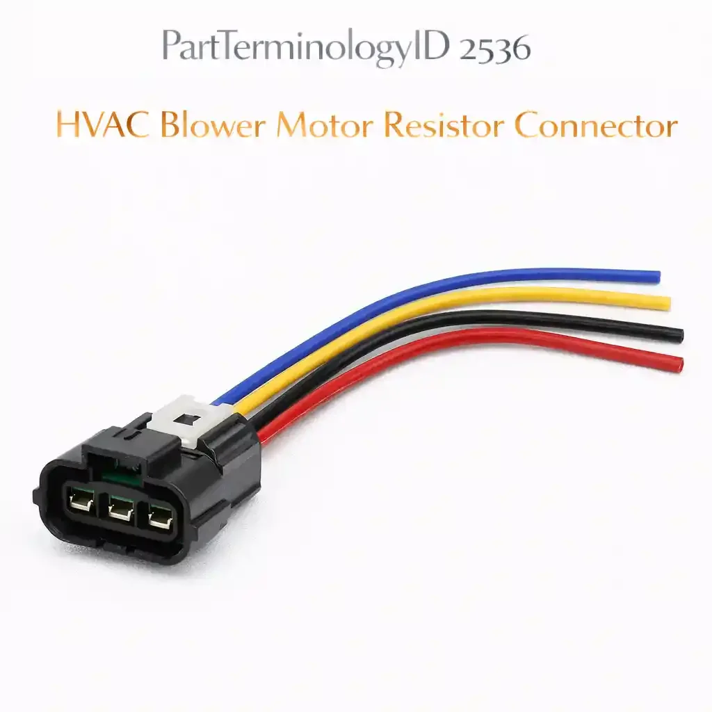
PartTerminologyID 2536, HVAC Blower Motor Resistor Connector, is the wiring harness connector body that mates with the blower motor resistor assembly, providing the electrical interface between the vehicle's HVAC control harness and the resistor pack terminals that carry the blower motor supply voltage, the ground return, the blower speed selection signals for each speed step, and on thermistor-equipped designs the thermal protection circuit signal. That definition covers the function correctly. It does not specify the terminal count, which ranges from three terminals on a basic two-speed resistor pack to seven or more on a multi-speed resistor assembly with a thermal cutout return circuit, the connector body housing series designation, the terminal pin gauge and current rating for each circuit position, the seal type, whether the connector uses individual wire seals for under-dash or under-hood blower motor locations or is unsealed for enclosed HVAC module installations, the connector lock type, whether it uses a friction lock or a primary latch with secondary connector position assurance, the wire entry direction, the resistor pack variant compatibility, whether the connector is designed for a conventional wire-wound resistor pack or a transistorized resistor module with a separate PWM control terminal, the blower motor resistor part number the connector is matched to, the terminal current rating at the blower motor supply position which carries the full blower motor operating current at the lowest speed step, or whether the listing covers the connector body only or a pigtail assembly with pre-installed terminals and wire. A listing under PartTerminologyID 2536 that provides vehicle year, make, and model without the terminal count, the resistor pack variant, the connector housing designation, and the terminal current rating at the blower supply position cannot be evaluated by any technician who has a heat-damaged or melted blower motor resistor connector and is confirming the replacement before removing the blower motor resistor from under the dash or firewall.
For sellers, PartTerminologyID 2536 occupies the intersection of two specification requirements that must be satisfied simultaneously: the terminal current rating requirement at the blower motor supply position, and the resistor pack variant compatibility requirement that differentiates conventional wire-wound resistor packs from transistorized blower motor control modules. The blower motor resistor connector must carry the full blower motor operating current at the lowest speed step, where all resistance elements are in series and the full motor current passes through the resistor pack rather than bypassing it through a relay. A connector that underrates the current at the blower supply terminal will overheat at that position during sustained low-speed operation, producing the characteristic melted-terminal failure that is the leading return scenario for this PartTerminologyID. A connector that has adequately rated terminals but is wired for a conventional resistor pack will have no provision for the PWM control terminal required by a transistorized blower motor control module, leaving the speed control signal unconnected and preventing the HVAC module from commanding blower speed variation.
The additional complexity specific to PartTerminologyID 2536 compared to the air charge temperature sensor connector (2524) is the current loading argument. The IAT sensor connector carries a milliamp-level resistive signal. The blower motor resistor connector carries the full blower motor operating current at the speed positions where the motor current flows through the resistor pack. On a typical passenger vehicle blower motor drawing 15 to 25 amperes at maximum speed, the connector's blower supply terminal carries that full current during operation. On a pickup truck or SUV with a large blower motor drawing 30 to 40 amperes, the supply terminal current is proportionally higher. The connector body and its terminal contact materials must maintain their dimensional stability and contact spring force at the operating temperature that results from carrying that current through whatever contact resistance exists at the terminal interface.
For sellers, the listing under this PartTerminologyID is only useful if it specifies the terminal count, the blower motor resistor part number or assembly designation, the resistor pack variant, the connector housing designation, the terminal current rating at the blower supply position, and whether the listing is a connector body only or a pigtail assembly. Without those six attributes, the listing cannot prevent the terminal current mismatch that produces the melted-connector failure mode, the resistor pack variant error that leaves the PWM control terminal unconnected, or the thermal failure from an undersized supply terminal that appears visually identical to a correctly rated replacement.
What the HVAC Blower Motor Resistor Connector Does
Carrying the blower motor speed control signals
On vehicles with a conventional wire-wound resistor pack, the blower motor resistor connector carries one terminal for each speed step below maximum speed, plus a blower motor supply terminal and a ground return terminal. At the lowest speed step, the full blower motor operating current flows from the supply terminal through the first resistor element in the pack to the motor, and the remaining resistor elements are in series in the circuit. This configuration places the maximum current at the supply terminal at all speed steps because the motor current path always begins at the supply terminal regardless of which speed step is selected.
At maximum blower speed, most designs use a relay to bypass the resistor pack entirely, routing current directly from the blower fuse to the motor without passing through the resistor connector. This means the maximum current at the resistor connector's supply terminal occurs not at the highest blower speed but at the lowest speed step, where the motor operates at reduced voltage and draws current from the harness through the resistor connector supply terminal continuously without relay bypass.
On vehicles with a transistorized blower motor control module, the connector carries a PWM control signal terminal in addition to the power supply and ground terminals. The HVAC module commands blower speed by varying the duty cycle of the PWM signal rather than by switching between fixed resistance steps. The transistorized module does not have separate terminal positions for individual speed steps. A connector wired for a conventional resistor pack will have terminal cavities for the individual speed step signals and no cavity for the PWM control terminal, making it physically incompatible with the transistorized module's connector interface.
Carrying the thermal cutout return signal
Many blower motor resistor assemblies include a thermal cutout or thermistor that opens the resistor circuit if the pack overheats from sustained operation at high current or from restricted airflow across the resistor elements. The thermal cutout return signal exits through the connector on a dedicated terminal that is separate from the speed step terminals. If the replacement connector lacks the thermal cutout return terminal cavity, the thermal protection circuit cannot complete its return path through the harness, and the thermal cutout function is disabled. An overheating resistor pack without a functioning thermal cutout will sustain damage to its resistor elements from a sustained overtemperature condition that the original design protected against.
Why the blower motor resistor connector is a high-current and high-heat environment component
The blower motor resistor connector operates at the junction of two heat sources: the resistive heating of the resistor pack elements that the blower airflow is supposed to cool, and the I²R heating of the connector's own terminals from the blower motor current. The resistor pack is mounted in the blower motor airstream specifically to use the blower's airflow for resistor element cooling. When the blower motor runs at low speed, the airflow across the resistor pack is reduced precisely when the full motor current is flowing through the pack at the lowest speed step. This combination of maximum current and minimum cooling produces the maximum operating temperature at the resistor pack and at the connector that mates with it.
Under-dash ambient temperatures at the blower motor resistor location can exceed 85 degrees Celsius during sustained low-speed operation in a hot vehicle. On firewall-mounted resistor assemblies with external exposure, ambient temperatures depend on under-hood conditions. The connector body must withstand this combined self-heating from terminal current and external ambient without softening at the terminal cavities in a way that allows the supply terminal to shift position and produce intermittent contact.
Pigtail assembly for heat-damaged connector replacement
When the blower motor resistor connector has been heat-damaged at the supply terminal, the harness wires immediately behind the connector at the supply circuit position typically show insulation discoloration, brittleness, or conductor discoloration from the localized overheating at that terminal contact face. A pigtail assembly that includes 200 to 300mm of new wire at all circuit positions allows the technician to cut the harness behind the heat-affected zone on all wires and splice the pigtail to confirmed undamaged wire rather than splicing a new connector body to wire that may have degraded insulation at the supply position. The pigtail wire gauge at the supply terminal position must match or exceed the original harness wire gauge to maintain the same current capacity.
The listing must state whether it is a connector body only or a pigtail assembly, the pigtail wire length in mm, and the wire gauge at each circuit position for pigtail designs. The wire gauge at the blower supply terminal position is the critical specification because it must carry the full blower motor operating current through the splice joint and along the new wire section to the harness.
The Specifications That Determine Correct Blower Motor Resistor Connector Fitment
Terminal count and circuit assignment
Three terminals for basic two-speed designs with supply, ground, and one speed step signal. Four to six terminals for multi-speed conventional resistor packs with individual speed step terminals. Add one terminal for thermal cutout return on designs with thermal protection. Add one PWM control terminal for transistorized blower motor control module designs in place of individual speed step terminals. State the count and the circuit assignment at each position.
Blower motor resistor assembly part number or designation
The primary fitment attribute. The terminal count, the terminal pitch, the connector body profile, and the resistor pack variant are all defined at the resistor assembly level. A vehicle application may have been produced with two different blower motor resistor assemblies across its production run, requiring two different connectors with the same vehicle application range but different resistor assembly designations.
Resistor pack variant
Conventional wire-wound resistor pack or transistorized blower motor control module. State the variant explicitly. A connector wired for a conventional resistor pack cannot be substituted for a connector wired for a transistorized module even if the external dimensions are similar, because the transistorized module requires a PWM control terminal cavity where the conventional pack has an additional speed step terminal.
Terminal current rating at the blower supply position
In amperes continuous. The blower supply terminal carries the full blower motor operating current at all speed steps below relay-bypassed maximum speed. The current rating must meet or exceed the maximum blower motor operating current for the specific vehicle and blower motor specification.
Connector body temperature rating
In degrees Celsius continuous ambient. Must exceed the maximum ambient temperature at the blower motor resistor connector location, accounting for both external ambient and self-heating from terminal current at the supply position.
Seal type
Individual wire seals with body-side seal for external or firewall-mounted resistor assemblies. Unsealed for resistor assemblies mounted within an enclosed HVAC module housing where the connector is protected from direct moisture exposure.
Lock type
Friction, primary latch, or primary with secondary CPA. State the CPA type for designs with secondary locks. A secondary CPA is particularly important on blower motor resistor connectors because the connector is subject to vibration from blower motor operation and thermal cycling from resistor heating that can work a primary-latch-only connector toward partial unseating over time.
Wire entry direction
Inline or right-angle. Must match the harness routing at the resistor assembly location. Right-angle entry connectors are common on under-dash mounted resistor assemblies where the harness routes parallel to the firewall.
Pigtail or connector body only
State explicitly. For pigtail assemblies, state the wire length and the wire gauge at each terminal position, with the supply terminal wire gauge called out separately as the current-critical circuit.
Status in New Databases
PIES/PCdb: PartTerminologyID 2536, HVAC Blower Motor Resistor Connector
PIES 8.0 / PCdb 2.0: No change
Top Return Scenarios
Scenario 1: "Supply terminal undersized for blower motor current, terminal melted at sustained low-speed operation within first winter"
The listing specified a blower motor resistor connector by vehicle year, make, and model without stating the terminal current rating at the supply position. The vehicle has a 30-ampere blower motor on its high-capacity HVAC system. The replacement connector is built for a standard 20-ampere blower motor application and its supply terminal is rated for 20 amperes continuous. During sustained low-speed blower operation in recirculation mode on a cold morning, the supply terminal carried 30 amperes through a 20-ampere-rated contact interface. The contact face operated above its thermal rating. Within the first season, the terminal had partially melted into the connector body at the supply cavity, increasing contact resistance and reducing blower motor voltage at low speed before the terminal deformed sufficiently to produce intermittent blower operation.
Prevention language: "Blower motor supply terminal current rating: [X] amperes continuous. Verify the current rating meets or exceeds the maximum blower motor operating current for your vehicle. The supply terminal carries the full blower motor current at every speed step below relay-bypassed maximum. An undersized supply terminal that operates at low-speed blower settings will produce progressive contact resistance increase and eventual terminal melt before the failure mode becomes an obvious blower malfunction."
Scenario 2: "Conventional resistor pack connector installed on transistorized blower motor control module, PWM terminal unconnected, no blower speed variation"
The listing specified a blower motor resistor connector by vehicle year, make, and model without stating the resistor pack variant. The vehicle has a transistorized blower motor control module that receives a PWM duty-cycle command from the HVAC module. The replacement connector has individual speed step terminal cavities for a conventional resistor pack and no cavity for the PWM control terminal. The PWM wire from the harness had no terminal connection point. The transistorized module received power and ground through the connector but received no PWM command signal. The blower motor ran continuously at its default low-speed output, providing no speed variation across any fan speed selector position.
Prevention language: "Resistor pack variant: [conventional wire-wound / transistorized PWM module]. The conventional resistor pack and the transistorized blower motor control module use different connectors with different terminal assignments. The transistorized module requires a PWM control terminal cavity that the conventional resistor pack connector does not have. A conventional connector installed on a transistorized module leaves the PWM signal wire unconnected and prevents any blower speed variation. Confirm the resistor pack variant before ordering."
Scenario 3: "Thermal cutout return terminal absent, thermal protection circuit disabled, resistor pack elements burned at first overtemperature event"
The listing specified a connector by vehicle fitment without indicating whether it included the thermal cutout return terminal. The original connector has five terminals including a dedicated thermal cutout return at pin 5. The replacement connector has four terminals covering supply, ground, and two speed step signals, with no cavity for the thermal cutout return. The thermal cutout circuit could not complete its return path through the harness. During a blocked cabin air filter event where restricted airflow reduced cooling across the resistor pack, the resistor elements heated to the thermal cutout trip point but the open thermal cutout circuit could not signal the HVAC module. The resistor pack elements sustained heat damage from the sustained overtemperature condition the thermal protection circuit was designed to prevent.
Prevention language: "Terminal count: [X terminals, including thermal cutout return / no thermal cutout terminal]. Verify the terminal count on the original connector before ordering. Connectors for resistor assemblies with thermal protection include a dedicated terminal for the thermal cutout return circuit. A connector that omits this terminal disables the thermal protection circuit and exposes the resistor pack elements to unprotected overtemperature damage during airflow restriction events."
Scenario 4: "Connector body only, harness wire insulation heat-degraded at supply position, splice made to discolored wire, insulation cracks within one season"
The original blower motor resistor connector was heat-damaged at the supply terminal position and the buyer sourced a connector body only. The harness wire at the supply circuit position showed light discoloration extending 40mm behind the original connector. The technician cut the harness 15mm behind the original connector at all positions and transferred the original terminals to the new connector body. Within one season of blower operation, the insulation at the splice-point on the supply wire had cracked from thermal cycling and vibration, exposing bare conductor. The exposed conductor contacted the adjacent speed step wire in the harness, producing a short circuit between the blower supply and the lowest speed step signal that caused the blower to operate at a single fixed speed regardless of the fan speed selection.
Prevention language: "Listing type: [connector body only / pigtail assembly with [X]mm of new wire including [Y]-gauge wire at the supply terminal position]. If the blower motor resistor connector shows heat damage at the supply terminal position, inspect the supply circuit harness wire for a minimum of 200mm behind the original connector for insulation discoloration, brittleness, or conductor discoloration before sourcing a connector body only. Heat damage to the supply wire insulation requires a pigtail assembly that places the splice in confirmed undamaged wire beyond the heat-affected zone."
Scenario 5: "Right-angle connector installed where inline is required, connector partially unseated from resistor assembly by harness routing tension, intermittent blower dropout"
The listing specified a blower motor resistor connector without stating the wire entry direction. The vehicle's harness routes perpendicular to the resistor assembly connector face, requiring an inline wire entry connector. The replacement connector has a right-angle wire entry that routes the harness parallel to the resistor assembly face. The harness routing tension at the right-angle entry pulled the connector body partially away from the resistor assembly mating terminals at the primary latch engagement point. Over 8,000 miles, the partial unseating produced intermittent contact at two of the four speed step terminals and caused random dropout at mid-range blower speeds.
Prevention language: "Wire entry direction: [inline / right-angle]. The wire entry direction must match the harness routing at the resistor assembly location. An inline connector on a harness that routes at right angles to the connector face will create routing tension that works against the primary latch. A right-angle connector on a harness that routes perpendicular to the connector face will pull the connector axially away from the mating terminals under vibration. Verify the wire entry direction of the original connector before ordering."
What to Include in the Listing
Core essentials
PartTerminologyID: 2536
Component: HVAC Blower Motor Resistor Connector
Blower motor resistor assembly part number or designation (mandatory, primary fitment attribute)
Resistor pack variant: conventional wire-wound or transistorized PWM module (mandatory)
Terminal count (mandatory)
Circuit assignment at each terminal position (mandatory)
Thermal cutout return terminal: present or absent (mandatory)
Blower supply terminal current rating in amperes (mandatory)
Connector body housing series designation (mandatory)
Connector body temperature rating in degrees Celsius (mandatory)
Seal type: individual wire seals with body-side seal or unsealed (mandatory)
Lock type: friction, primary latch, or primary with CPA (mandatory)
Wire entry direction: inline or right-angle (mandatory)
Mating resistor assembly terminal gender and pitch (mandatory)
Pigtail or connector body only (mandatory)
Pigtail wire length in mm and wire gauge per circuit position for pigtail assemblies, with supply terminal wire gauge called out separately (mandatory)
Quantity: 1
Fitment essentials
Year/make/model/submodel
Blower motor resistor assembly designation as primary fitment attribute above vehicle application
Resistor pack variant as secondary fitment attribute
Engine designation where blower motor specification varies by powertrain
Dimensional essentials
Connector body overall length in mm
Connector body width in mm
Connector body depth in mm
Terminal pitch in mm
Terminal cavity depth in mm
Image essentials
Connector from the mating face showing terminal count and cavity arrangement with each position labeled by circuit assignment
Connector from the wire entry side showing seal type and wire entry direction
Pigtail assembly shown full length with wire gauge and length callout for each circuit position, with the supply terminal wire called out by gauge separately
Heat-damaged original connector shown alongside undamaged replacement to illustrate the supply terminal melt pattern that brings buyers to this PartTerminologyID
Thermal cutout return terminal position highlighted separately for listings that include the thermal protection circuit
Catalog Checklist for ACES/PIES Teams
PartTerminologyID = 2536
Require blower motor resistor assembly designation as primary fitment attribute (mandatory)
Require resistor pack variant (mandatory)
Require terminal count (mandatory)
Require circuit assignment map by terminal position (mandatory)
Require thermal cutout return terminal presence or absence (mandatory)
Require blower supply terminal current rating (mandatory)
Require connector body temperature rating (mandatory)
Require seal type (mandatory)
Require wire entry direction (mandatory)
Require pigtail versus connector body only designation (mandatory)
Differentiate from blower motor resistor (PartTerminologyID 2534): the resistor is the resistance element assembly that steps the blower motor voltage; the connector is the harness interface to the resistor assembly terminals; a damaged connector does not require resistor pack replacement if the resistor elements are confirmed functional
Differentiate from blower motor (PartTerminologyID 2533): the blower motor is the electromechanical fan assembly; the resistor connector is the harness interface to the speed-control component upstream of the motor; both components are in the same circuit but the connector failure is specifically at the resistor assembly interface, not at the motor
Differentiate from HVAC relay (PartTerminologyID 2516): the HVAC relay bypasses the resistor pack at maximum blower speed; the resistor connector interfaces the harness to the speed control assembly at all sub-maximum speed steps; both are in the blower motor circuit but at different points with different current and thermal profiles
Flag blower supply terminal current rating as mandatory: the supply terminal melted-connector failure is the dominant return scenario for this PartTerminologyID and is invisible at the specification stage when current rating is absent from the listing
Flag resistor pack variant as mandatory: a conventional resistor pack connector and a transistorized blower motor control module connector may have identical external dimensions but different terminal assignments; a variant mismatch produces a no-blower-speed-variation failure from the first operation
Flag thermal cutout return terminal as mandatory: a connector that omits the thermal cutout return terminal on a resistor assembly designed with thermal protection disables the safety function silently
FAQ (Buyer Language)
How do I identify whether my vehicle has a conventional resistor pack or a transistorized blower motor control module?
The most reliable method is to count the terminals on the original connector and identify the circuit assignment at each position. A conventional resistor pack connector has individual terminal positions for each speed step, typically labeled LO, M1, M2, and M3 or equivalent, plus a supply terminal and a ground. A transistorized blower motor control module connector has a supply terminal, a ground terminal, and a PWM control terminal, with no individual speed step terminals. If the original connector has already been damaged, identify the blower motor resistor assembly part number from the assembly and cross-reference it to confirm the variant. On post-2005 vehicles with automatic temperature control or manual HVAC systems using a rotary encoder rather than discrete speed steps, a transistorized module is more likely.
Can I use a pigtail assembly if my original harness wires are undamaged?
Yes. A pigtail assembly is always acceptable as a replacement for a connector body only, regardless of the harness wire condition. The pigtail is preferred when the original connector shows heat damage at the supply terminal position because the supply wire insulation in the heat-affected zone may show degradation that is not visually obvious. If the original harness wires are confirmed undamaged and undegraded for at least 200mm behind the connector at all circuit positions including the supply wire, a connector body only is an acceptable alternative. For the supply terminal circuit specifically, use a magnifier to inspect the wire insulation for any stiffness, discoloration, or surface cracking before choosing a connector body only over a pigtail.
My blower motor resistor connector melted at one terminal. Do I need to replace the resistor pack too?
Not necessarily. Confirm the resistor pack element continuity with an ohmmeter across each speed step terminal pair before replacing the resistor. If the resistance values across each step match the specification and there is no evidence of element burnout, the resistor pack is serviceable and only the connector requires replacement. However, inspect the mating terminals on the resistor assembly for discoloration, pitting, or deformation from the heat event at the connector. If the resistor assembly's mating terminal surfaces are damaged, they will produce elevated contact resistance with a new connector and the overheating cycle will repeat. In that case, replace both the connector and the resistor assembly.
What is the difference between the blower motor resistor connector and the blower motor connector?
The blower motor resistor connector at PartTerminologyID 2536 interfaces the harness to the blower motor resistor assembly, which is the speed control component that steps the motor voltage by inserting resistance into the motor circuit. It carries speed control signals and the blower motor supply current at each speed step. The blower motor connector interfaces the harness directly to the blower motor terminals and carries the full blower motor operating voltage and current at the selected speed. Both connectors are in the blower motor circuit, but they are at different locations and carry different voltages depending on the selected speed step.
Cross-Sell Logic
Blower Motor Resistor (PartTerminologyID 2534): If the connector melt was caused by a failing resistor pack that increased its contact resistance over time and produced localized heating at the resistor assembly terminals, the resistor pack requires inspection and likely replacement at the same service event. A resistor pack with damaged mating terminals will cause the failure cycle to repeat with a new connector.
Blower Motor (PartTerminologyID 2533): A blower motor that is failing mechanically and drawing above-rated current will overheat the resistor pack and the resistor connector. Confirm the blower motor current draw before attributing the connector melt to the connector specification alone.
HVAC Relay (PartTerminologyID 2516): If the blower motor relay that bypasses the resistor pack at maximum speed is failing and not bypassing the pack correctly, the resistor pack and connector will carry current at maximum speed that they are not designed for, accelerating heat damage.
Cabin Air Filter: A clogged cabin air filter reduces airflow across the resistor pack elements, reducing the cooling that the blower airstream provides to the resistor assembly and elevating resistor and connector temperatures at all speed steps. Recommend inspection at the same service event.
Wiring Repair Kit: For splice connections required during pigtail installation, a heat-shrink splice connector kit sized for the specific wire gauge at the supply terminal position ensures a watertight, low-resistance splice joint that does not add contact resistance to the highest-current circuit in the connector.
Frame as "the resistor pack controls what voltage the blower motor receives. The connector carries the current that the resistor pack uses to do that. If the connector fails, the resistor pack cannot control the motor. If the resistor pack fails, the connector overheats. Both components are confirmed at the same service event."
Final Take for PartTerminologyID 2536
HVAC Blower Motor Resistor Connector (PartTerminologyID 2536) is the connector PartTerminologyID in this series where the terminal current rating at the supply position is the attribute that produces the most consequential invisible fitment error: an undersized supply terminal that seats correctly, locks correctly, and appears installed correctly, but carries blower motor current above its rated limit during every sustained low-speed blower operation and produces progressive terminal melt that presents as a blower motor or HVAC control fault rather than a connector specification error. The supply terminal is underloaded at maximum blower speed due to relay bypass and overloaded at low blower speed where the full motor current flows through the resistor circuit. The low-speed overload condition occurs during exactly the operating modes where drivers run the blower for extended periods: defrost at idle, cabin temperature maintenance in traffic, quiet low-speed ventilation. A supply terminal rated for a standard-output blower on a high-output blower application will melt during the normal operating conditions for which the blower is used most frequently.
State the blower motor resistor assembly designation in the primary fitment attribute position. State the terminal count. State the circuit assignment at each position. State the resistor pack variant. State the blower supply terminal current rating. State the thermal cutout return terminal presence or absence. State the connector body temperature rating. State the seal type. State the wire entry direction. State the pigtail versus connector body designation. Include the current rating note and the heat-affected harness inspection note. That is the same listing strategy as every other PartTerminologyID in this series: specific attributes at every level to become a listing buyers can act on without guessing. For PartTerminologyID 2536, the supply terminal current rating and the resistor pack variant are the two attributes that determine whether the replacement connector restores blower speed control to full function or fails silently during the operating conditions the buyer uses most.