Air Charge Temperature Sensor Connector (PartTerminologyID 2524): Why Terminal Count, Seal Type, and Housing Designation Prevent ECM Signal Faults
Written by Arthur Simitian | PartsAdvisory
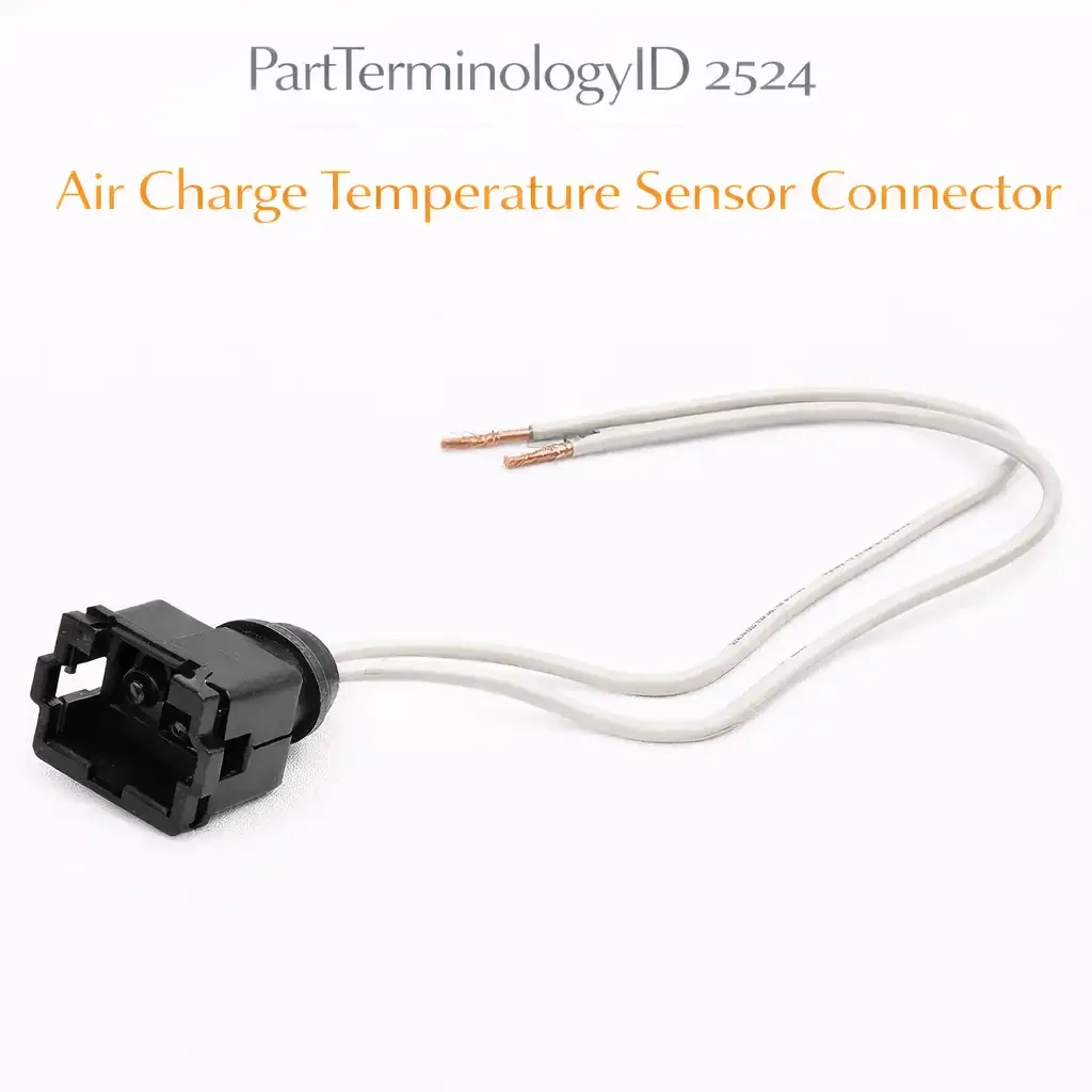
PartTerminologyID 2524, Air Charge Temperature Sensor Connector, is the wiring harness connector body that mates with the air charge temperature sensor, also called the intake air temperature sensor or IAT sensor, providing the electrical interface between the engine control harness and the sensor terminals that carry the resistive signal from the sensor's negative temperature coefficient thermistor element to the engine control module, which uses the signal to calculate air density for fuel injection and ignition timing corrections. That definition covers the function correctly. It does not specify the terminal count, which is almost always two for a simple NTC thermistor sensor but may be three or four on sensors integrated with the mass air flow sensor housing or with a combined IAT and manifold absolute pressure sensor, the connector body housing series designation and manufacturer, the terminal pin gauge and contact force specification, the seal type, whether the connector uses a body-side seal, individual wire seals, or is unsealed for dry intake manifold locations, the connector body keying and polarizing rib configuration, the terminal pin material and plating, the connector lock type, whether it uses a friction lock, a primary latch, or a primary latch with secondary connector position assurance, the wire entry direction, the overall connector body dimensions and profile for applications where the connector must fit within the intake manifold clearance envelope, the mating sensor terminal designation, whether the sensor uses male pins or female sockets at its harness interface, or whether the listing covers the connector alone or a pigtail assembly with a short section of new wire and new terminals pre-installed in the replacement connector body. A listing under PartTerminologyID 2524 that provides vehicle year, make, and model without the connector housing designation, the seal type, and the mating sensor specification cannot be evaluated by any technician who has a heat-damaged, broken, or corroded IAT sensor connector and is confirming the replacement before removing the intake air duct or manifold section that provides access to the original connector.
For sellers, PartTerminologyID 2524 serves a buyer who has confirmed that the engine is setting a diagnostic trouble code in the P0110 to P0114 range, which covers intake air temperature sensor circuit faults including rationality failures, high input, low input, and intermittent circuit, and has traced the fault to the connector rather than to the sensor itself or to the harness wiring upstream of the connector. The connector failure modes that bring a buyer to this PartTerminologyID are corroded terminals from moisture intrusion into the intake air path, a heat-damaged connector body from proximity to the exhaust manifold or turbocharger on some engine configurations, a cracked or broken connector body from impact during air filter replacement or intake duct servicing, and a pushed-back or spread terminal pin from a previous connector extraction that was performed without the correct terminal release tool.
The additional complexity specific to PartTerminologyID 2524 compared to the HVAC switch connector (2520) and the HVAC relay connector (2516) is the ECM signal integrity argument. HVAC connectors carry control signals where a modest degradation in contact quality produces a functional fault that is immediately observable: the blower does not respond, the mode door does not move. The air charge temperature sensor connector carries a resistive signal where the ECM interprets the resistance presented at the sensor input terminals as a temperature reading. A connector with elevated contact resistance from corrosion or a spread terminal pin adds resistance in series with the sensor's thermistor resistance, shifting the signal toward the high-resistance end of the temperature scale and causing the ECM to calculate an intake air temperature that is colder than actual. The consequence is an overly rich fuel correction and retarded ignition timing, producing fuel economy loss and potentially elevated hydrocarbon emissions without any obvious drivability symptom until the contact resistance is high enough to push the circuit voltage outside the ECM's rationality window and set a fault code.
For sellers, the listing under this PartTerminologyID is only useful if it specifies the connector housing designation, the terminal count, the seal type, the mating sensor terminal specification, and whether the listing covers the connector body only or a pigtail assembly. Without those five attributes, the listing cannot serve the technician who has the original connector in hand, has confirmed the terminal count and seal type from the original, and needs the housing designation cross-reference to source the replacement body.
What the Air Charge Temperature Sensor Connector Does
Maintaining the signal circuit integrity required for accurate temperature measurement
The IAT sensor connector carries the two-wire signal circuit between the ECM and the sensor thermistor. The ECM supplies a reference voltage, typically 5 volts, through one terminal and measures the return voltage through the other terminal after the current has passed through the sensor thermistor. The resistance of the thermistor decreases as temperature increases according to the sensor's calibrated resistance-temperature curve. The ECM converts the measured voltage to a resistance value and looks up the corresponding temperature from the sensor's calibration table stored in the ECM memory.
A connector terminal with elevated resistance from corrosion or partial contact adds a fixed resistance to the signal circuit that is indistinguishable from a change in thermistor resistance. A contact resistance of 50 ohms in a connector that should contribute zero ohms will cause the ECM to read the circuit as 50 ohms warmer at the cold end of the thermistor curve or 50 ohms colder at the warm end, depending on which terminal carries the elevated resistance. For a typical NTC thermistor with 2,500 ohms resistance at 20 degrees Celsius, a 50-ohm contact resistance produces an error of approximately 2 degrees. At the same thermistor at minus 20 degrees Celsius where the resistance is approximately 10,000 ohms, a 50-ohm error produces only 0.4 degrees of error because the thermistor resistance is much larger than the contact resistance. The contact resistance error is therefore most significant at warm intake temperatures where the thermistor resistance is low and the contact resistance represents a larger fraction of the total circuit resistance.
The seal type and its consequence for intake air environment applications
The air charge temperature sensor is mounted in the intake air path, which is not a sealed environment. Pulsing air flow, condensation from the air charge cooler on turbocharged engines, and moisture from rain and washing carry water into the intake air path and past the sensor body. The connector mating face is directly exposed to this moisture through the gap between the sensor body and the connector housing at the mating interface.
A connector with individual wire seals at each terminal entry and a body-side seal at the mating face provides moisture exclusion that prevents condensation from reaching the terminal contact zone. An unsealed connector in the same application allows moisture to bridge the terminal contact surfaces, providing a parallel conductive path across the thermistor signal circuit that reduces the apparent resistance and causes the ECM to read an artificially high intake air temperature. On a turbocharged engine with a charge air cooler, the condensate volume in the intake path is sufficient to produce a measurable signal shift in an unsealed connector within one cooling season.
The listing must state the seal type and must match the seal type of the original connector. An unsealed replacement connector installed in an application that had a sealed original will introduce moisture sensitivity that the original design excluded.
Pigtail assembly versus connector body only
A pigtail assembly includes a short section of new wire, typically 150 to 300mm, with new terminals pre-installed in the replacement connector body. The pigtail allows the technician to splice the new assembly into the original harness by cutting the original harness wires behind the damaged connector and splicing the pigtail wires to the cut ends, rather than extracting the original terminals from the damaged connector body and transferring them to the replacement body.
The pigtail approach is appropriate when the original terminals are corroded or deformed beyond reuse, when the original harness wires are damaged or brittle at the connector entry, or when the technician does not have the terminal extraction and insertion tools required for a connector body-only replacement. The connector body-only approach is appropriate when the original terminals are clean and undamaged and can be extracted and reused, preserving the full harness wire length without a splice joint.
The listing must state whether it is a connector body only or a pigtail assembly and must give the pigtail wire length if it is an assembly, so the technician can confirm the splice point will fall in an accessible location within the harness routing.
The ECM rationality window and the signal fault threshold
The ECM monitors the IAT sensor signal against a rationality window defined by the expected temperature range for normal intake air conditions. A signal that falls outside this window triggers a fault code regardless of whether the underlying cause is a failed sensor, a connector contact resistance problem, or a wiring fault. The fault code generation threshold is typically reached when the contact resistance produces an apparent temperature error of 10 to 20 degrees from the rationality comparison value, which may require hundreds of ohms of contact resistance at warm temperatures where the thermistor resistance is low.
Below the fault code threshold, the contact resistance produces a temperature error that is too small to trigger a code but large enough to affect fuel trim and timing. This sub-threshold signal degradation is the reason a technician may replace the IAT sensor and observe temporary improvement before the new sensor's clean connector begins to accumulate the same contact corrosion that produced the original fault, eventually reproducing the code. Replacing the connector at the same service event as the sensor prevents the sub-threshold corrosion from the original connector from affecting the new sensor's signal.
The Specifications That Determine Correct Fitment
Terminal count
Almost always two for a standalone IAT sensor. Three or four for integrated IAT and MAP or IAT and MAF sensor designs. Must be confirmed from the original connector before ordering.
Connector body housing series designation
The OEM or aftermarket connector housing series designation. The primary cross-reference attribute for a technician sourcing through a connector catalog.
Seal type
Unsealed, body-side sealed only, or fully sealed with individual wire seals and body-side seal. Must match the original connector's environmental protection level for the application.
Mating sensor terminal specification
Whether the connector accepts male pins or female sockets at the sensor mating interface. Must match the sensor's terminal gender.
Pigtail assembly or connector body only
State explicitly. For pigtail assemblies, state the pigtail wire length in mm and the wire gauge.
Wire entry direction
Inline or right-angle. Must match the harness routing geometry at the IAT sensor location.
Lock type
Friction, primary latch, or primary with secondary CPA. State CPA type if present.
Temperature rating of connector body material
In degrees Celsius. For applications near the turbocharger or the exhaust manifold where the connector body is exposed to elevated ambient temperatures.
Status in New Databases
PIES/PCdb: PartTerminologyID 2524, Air Charge Temperature Sensor Connector
PIES 8.0 / PCdb 2.0: No change
Top Return Scenarios
Scenario 1: "Unsealed replacement connector, sealed original, condensate in intake path causes signal shift on turbocharged engine"
The replacement connector is unsealed. The original connector used individual wire seals and a body-side seal. The turbo engine's charge air cooler produces condensate in the intake path that reaches the connector mating face. Within one cooling season, moisture had bridged the terminal contacts inside the unsealed replacement connector, adding a parallel conductive path across the thermistor signal that caused the ECM to read intake air temperature approximately 15 degrees above actual on cold mornings. The P0113 high input code did not set because the signal was within the rationality window, but the elevated temperature reading retarded ignition timing by 3 degrees during warm-up.
Prevention language: "Seal type: [unsealed / body-side sealed / fully sealed with individual wire seals]. The original connector for this application uses [individual wire seals and a body-side seal] to exclude moisture from the intake air path. Specify a replacement connector with the same seal type. An unsealed replacement in a sealed application will allow intake path moisture to reach the terminal contact zone, adding a parallel conductive path across the thermistor signal that shifts the ECM's temperature reading without necessarily setting a fault code."
Scenario 2: "Connector body only, original terminals corroded, transferred corroded terminals reproduce the contact resistance fault"
The listing covered a connector body only without a pigtail option. The buyer extracted the original terminals from the damaged connector body and transferred them to the replacement body. The original terminals had moderate surface corrosion on the contact faces from moisture intrusion. The transferred corroded terminals reproduced the contact resistance that had caused the original P0111 rationality code. The new connector body housed the original fault mechanism.
Prevention language: "Listing type: [connector body only / pigtail assembly with [X]mm of new wire and new terminals]. If your original terminals are corroded, spread, or otherwise damaged, specify the pigtail assembly rather than the connector body only. Transferring corroded original terminals into a new connector body reproduces the contact resistance fault that generated the original code. New terminals in a new connector body eliminate the contact corrosion entirely."
Scenario 3: "Integrated IAT and MAP sensor, two-terminal IAT connector ordered, four-terminal integrated connector required"
The listing specified an air charge temperature sensor connector by vehicle year, make, and model without stating the terminal count or the sensor type. The vehicle has a combined IAT and MAP sensor in a single housing with a four-terminal connector. A two-terminal standalone IAT connector arrived. The four-terminal integrated sensor connector has a completely different body profile and terminal arrangement from the two-terminal standalone IAT connector.
Prevention language: "Terminal count: [2 terminals, standalone IAT sensor / 4 terminals, integrated IAT and MAP sensor]. Verify the sensor type on your vehicle before ordering. Vehicles equipped with a combined IAT and MAP sensor in a single housing use a four-terminal connector that is a different body profile and housing designation from the two-terminal standalone IAT sensor connector. Confirm the terminal count on your original connector before ordering."
Scenario 4: "Heat-damaged connector body, turbocharger proximity, replacement has same temperature rating as original, cracked again within 6 months"
The original connector body was cracked and discolored from heat proximity to the turbocharger. The replacement connector was sourced by vehicle fitment without a temperature rating confirmation. The replacement body uses the same thermoplastic material as the original with the same 85-degree Celsius temperature rating. The turbocharger heat soak at that location regularly reaches 110 degrees Celsius. The replacement body began cracking within 6 months.
Prevention language: "Connector body temperature rating: [X] degrees Celsius continuous. For applications where the IAT sensor is located within [X]mm of the turbocharger or exhaust manifold, verify the connector body temperature rating exceeds the maximum ambient temperature at the installation location. If the original connector was heat-damaged, specify a replacement with a higher temperature rating or reroute the connector with a heat shield before installing the original-spec replacement."
What to Include in the Listing
Core essentials
PartTerminologyID: 2524
component: Air Charge Temperature Sensor Connector
terminal count (mandatory)
connector body housing series designation (mandatory)
seal type: unsealed, body-side sealed, or fully sealed with wire seals (mandatory)
mating sensor terminal gender: male pin or female socket (mandatory)
lock type: friction, primary latch, or primary with CPA (mandatory)
wire entry direction: inline or right-angle (mandatory)
connector body temperature rating in degrees Celsius (mandatory)
pigtail or connector body only (mandatory)
pigtail wire length in mm and wire gauge for pigtail assemblies (mandatory)
terminal material and plating (mandatory)
quantity: 1
Catalog Checklist for ACES/PIES Teams
PartTerminologyID = 2524
require terminal count (mandatory)
require connector housing designation (mandatory)
require seal type (mandatory)
require pigtail versus connector body only designation (mandatory)
require connector body temperature rating (mandatory)
differentiate from mass air flow sensor connector: the MAF sensor connector carries the frequency or analog voltage output signal from the MAF sensor to the ECM and may share a housing with the IAT sensor on integrated designs; a standalone MAF connector has a different terminal count and housing designation from a standalone IAT connector; verify the sensor type before specifying the connector
differentiate from manifold absolute pressure sensor connector: the MAP sensor connector carries the pressure-proportional voltage signal from the MAP sensor; on vehicles with a combined IAT and MAP sensor, both signals share a single connector body; the terminal count is the distinguishing attribute between a standalone IAT connector and a combined IAT and MAP connector
flag seal type as mandatory: an unsealed replacement in a sealed application introduces moisture sensitivity that produces sub-threshold signal errors that do not generate fault codes but affect fuel trim and timing; the seal type must match the original
flag pigtail versus connector body designation as mandatory: the most consistent cause of a repeat fault after connector replacement is the transfer of corroded original terminals into the new connector body; the pigtail option with new terminals eliminates this failure mode
Final Take for PartTerminologyID 2524
Air Charge Temperature Sensor Connector (PartTerminologyID 2524) is the sensor connector PartTerminologyID where the seal type and the pigtail versus connector body designation together determine whether the replacement eliminates the original fault entirely or partially reproduces it through a transferred terminal or a moisture ingress path that was sealed in the original. The ECM cannot distinguish between a thermistor resistance shift from temperature change and a contact resistance shift from corrosion, which means a connector that partially reproduces the original fault will produce a sub-threshold signal error that affects fuel trim without setting a code, making it the most diagnostically elusive repeat fault in the sensor connector series.
State the terminal count. State the connector housing designation. State the seal type. State the mating sensor terminal gender. State the lock type. State the temperature rating. State whether the listing is a connector body only or a pigtail assembly, and if it is a pigtail, state the wire length and gauge. That is the same listing strategy as every other PartTerminologyID in this series: specific attributes at every level to become a listing buyers can act on without guessing. For PartTerminologyID 2524, the seal type and the pigtail designation are the two attributes that determine whether the replacement connector allows the new or reused sensor to deliver an uncontaminated temperature signal to the ECM from the first cold start after installation.