HVAC Switch Connector (PartTerminologyID 2520): Why Terminal Count, Pin Arrangement, and Lock Type Prevent Control Signal Faults
Written by Arthur Simitian | PartsAdvisory
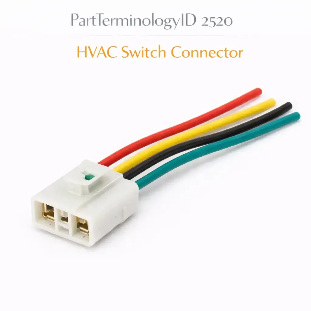
PartTerminologyID 2520, HVAC Switch Connector, is the wiring harness connector body that mates with the HVAC control switch assembly, providing the electrical interface between the vehicle's HVAC control harness and the switch terminals that carry the blower speed selection signals, the mode selection signals, the temperature blend door actuator control signals, the compressor request signal, and the recirculation mode signal to the HVAC control module or directly to the controlled devices. That definition covers the function correctly. It does not specify the terminal count, the connector body housing series designation, the terminal pin arrangement within the connector body, the terminal pin gauge and current rating for each circuit position, whether the switch connector mates with a rotary switch, a sliding switch, a push-button switch panel, or an electronic touch control panel, the connector lock type, whether the connector uses a friction lock, a primary latch, or a secondary connector position assurance lock, the wire seal type for applications where moisture intrusion into the HVAC control housing is a concern, the connector body gender, whether the harness-side connector is a female socket body mating with male pins on the switch or a male pin body mating with female sockets on the switch, the connector body keying, the wire entry direction, the connector body material and temperature rating, whether a single connector or multiple connectors serve the HVAC switch assembly depending on the control system complexity, or whether the listing covers the complete switch connector set or a single connector from a multi-connector switch interface. A listing under PartTerminologyID 2520 that provides vehicle year, make, and model without the terminal count, the connector body housing designation, the pin arrangement, and the mating switch type cannot be evaluated by any technician who has a damaged or broken HVAC switch connector and is confirming the replacement before removing the control panel from the dashboard.
For sellers, PartTerminologyID 2520 occupies a different diagnostic entry point than PartTerminologyID 2516, the HVAC Relay Connector. The relay connector buyer has visible heat damage from sustained high current through a resistive contact. The switch connector buyer typically has a physical breakage: a broken lock tab from forced removal during HVAC switch replacement, a cracked connector body from an impact during dash disassembly, a pushed-back terminal pin from a previous technician who did not use the correct terminal extraction tool, or a corroded terminal from moisture that entered the connector through a broken wire seal. The switch connector rarely fails from thermal damage because the control signal currents through the switch connector are low, typically under 5 amperes for all circuits including the blower speed signals, and do not generate significant heat even with modest contact resistance.
The additional complexity specific to PartTerminologyID 2520 compared to the relay connector (2516) is the multi-connector interface argument. A simple HVAC switch with four or five discrete circuits uses a single connector. A complex HVAC control panel with dual-zone temperature control, separate blower speed control, multiple mode selection positions, and recirculation control may use two, three, or four separate connectors on the back of the switch panel, each serving a defined group of circuits and each requiring individual replacement if damaged. The listing must specify whether it covers the complete switch connector set or a single connector from a multi-connector interface, and must identify which connector position it covers when the interface uses multiple connectors.
For sellers, the listing under this PartTerminologyID is only useful if it specifies the terminal count, the connector body housing designation, the mating switch type, the single-connector or multi-connector set designation, and the connector position within a multi-connector interface. Without those five attributes, the listing cannot serve a technician who has one of three connectors damaged on a dual-zone HVAC control panel and needs to confirm that the replacement covers the specific damaged position.
What the HVAC Switch Connector Does
Interfacing the control harness to the switch terminal field
The HVAC switch connector provides the harness-side termination for every circuit that the HVAC switch controls. On a simple manual HVAC system with a three-speed blower rotary switch, a mode rotary switch, and a temperature blend rotary switch, the switch connector may carry six to ten circuit wires covering the power supply to each switch, the output signals to the blower motor resistor pack or speed controller, the mode door actuator, and the blend door actuator, plus signal returns and ground. On a complex automatic climate control system, the switch panel may interface with the climate control module through a data bus connector and separate analog signal connectors, increasing the total terminal count to twenty or more across multiple connector bodies.
The connector's terminal pins must make reliable contact with the switch terminal field at each pin position to maintain all controlled circuits simultaneously. A single terminal pin that has pushed back into the connector body, losing contact with the switch pin it was designed to mate with, will disable the specific circuit that pin carries while leaving all other circuits functional. This selective fault is the diagnostic signature of a pushed-back terminal: one HVAC function is inoperative while all others work normally, and the fault clears when the connector is pressed firmly against the switch and recurs when it is released.
Why the lock type argument matters for switch connectors specifically
HVAC switch connectors in the dashboard are accessed during every HVAC switch replacement event. A technician who removes the HVAC switch without first releasing the connector's secondary connector position assurance lock will apply extraction force to the primary latch before the secondary lock has been disengaged, breaking the primary latch tab. A primary latch tab broken during incorrect removal is the most common physical damage mode for switch connectors and is the reason most buyers arrive at PartTerminologyID 2520 with a functionally intact switch and a connector with a broken latch.
The replacement connector must have the same lock type as the original: a connector with a primary latch only cannot be substituted for a connector with a primary latch and a secondary CPA lock without changing the release procedure required for future switch replacements. The listing must state the lock type so the buyer can confirm the replacement matches the original's retention system.
The pin arrangement and keying argument
HVAC switch connectors use keyed housings to ensure the connector can only mate with the switch in the correct orientation, preventing incorrect circuit assignments from a rotated or mirrored installation. The keying is typically a combination of asymmetric housing wall thickness, a polarizing rib on one side of the connector body, and asymmetric terminal cavities that prevent a mirror-image insertion. A replacement connector with the same terminal count but different keying will either not mate with the switch at all, which is immediately detected, or will mate in a misaligned position where some terminals engage the wrong switch pins, which is not detected until the HVAC system is operated and incorrect function is observed.
The pin arrangement within the connector body determines which circuit each terminal position carries. On OEM harnesses, the circuit assignment at each pin position is fixed and must match between the original and the replacement connector body. A replacement connector body with the same housing dimensions but a different internal pin cavity arrangement will accept the original harness terminals in positions that carry the wrong circuits to the wrong switch pins.
The Specifications That Determine Correct Fitment
Terminal count and circuit assignment
The number of terminal positions and the circuit each position carries. For multi-connector switch interfaces, the terminal count per connector body rather than the total switch interface terminal count.
Connector body housing series designation
The OEM or aftermarket connector housing series. Enables direct cross-reference to the replacement body in the technician's connector catalog.
Mating switch type
Rotary, sliding, push-button, or electronic panel. The switch type influences the connector body profile and the depth of insertion required for full terminal engagement.
Single connector or multi-connector set
Whether the listing covers a single connector body or the complete set of connectors for the switch interface. For multi-connector interfaces, state the position designation of the specific connector covered.
Lock type
Friction lock, primary latch only, or primary latch with secondary CPA lock. State the CPA lock type: slide CPA or flip CPA.
Wire entry direction
Inline or right-angle. Must match the harness routing behind the dash panel.
Wire seal type
Unsealed for dry interior applications or single-wire seals for applications where moisture intrusion into the dash panel is a concern from HVAC condensate or windshield leak paths.
Terminals included status
Connector body only, or connector body with new terminals and terminal extraction tool.
Status in New Databases
PIES/PCdb: PartTerminologyID 2520, HVAC Switch Connector
PIES 8.0 / PCdb 2.0: No change
Top Return Scenarios
Scenario 1: "Single connector ordered for three-connector switch interface, wrong position covered, damaged connector not replaced"
The HVAC control panel uses three separate connectors on the rear of the switch assembly. The center connector, which carries the blower speed and mode selection signals, has a broken lock tab from incorrect removal. The listing for the replacement connector specified the vehicle year, make, and model without stating the connector position within the multi-connector interface. The left connector arrived, which carries the temperature blend and recirculation signals. The damaged center connector was not replaced and the switch panel was reinstalled with the broken center connector tab.
Prevention language: "Connector position: [left / center / right] connector in the [X]-connector HVAC switch interface. This listing covers the [center] connector only. The HVAC switch on this vehicle uses [X] separate connectors. Verify the damaged connector position matches this listing before ordering. The left, center, and right connectors have different terminal counts and different circuit assignments and are not interchangeable."
Scenario 2: "Primary latch with CPA lock connector, replacement is primary latch only, next switch replacement breaks new latch from incorrect removal"
The original connector uses a primary latch with a slide-type secondary CPA lock. The replacement connector has a primary latch only without a CPA lock. The replacement was installed and functioned correctly. At the next switch replacement event two years later, the technician applied the same two-step release procedure used for the original CPA-equipped connector but encountered no secondary lock resistance. Uncertain whether the CPA had already released, the technician applied extraction force while the primary latch was still engaged and broke the primary latch tab of the new connector.
Prevention language: "Lock type: primary latch with [slide / flip] secondary CPA lock. The replacement connector must have the same lock type as the original to maintain the correct release procedure for future switch replacements. A connector with a primary latch only substituted for an original with a primary latch and CPA lock changes the release procedure at the next switch service event and increases the probability of latch breakage from technicians expecting a two-step release."
Scenario 3: "Same terminal count, different pin cavity arrangement, blower speed and mode circuits transposed, HVAC mode inoperable"
The replacement connector body has the same terminal count as the original but a different internal pin cavity arrangement from a different production run of the same connector series. When the original harness terminals were transferred into the replacement body at their original positions, the blower speed signal terminal and the mode selection signal terminal were transposed relative to the switch pin field. The blower speed control functioned correctly but the mode selection produced no response from the mode door actuator.
Prevention language: "Connector body housing designation: [series / part number]. Pin cavity arrangement: [diagram or position map]. Verify the pin cavity arrangement of the replacement connector body matches the original before transferring harness terminals. Different production runs of the same connector housing series may have different internal cavity arrangements. Transfer terminals to the replacement body in the position mapping specified for this connector designation, not in the position order they occupied in the original body."
What to Include in the Listing
Core essentials
PartTerminologyID: 2520
component: HVAC Switch Connector
terminal count (mandatory)
connector body housing series designation (mandatory)
mating switch type: rotary, sliding, push-button, or electronic (mandatory)
single connector or multi-connector set designation (mandatory)
connector position within multi-connector interface: left, center, right, or designated label (mandatory for multi-connector interfaces)
circuit assignment map by terminal position (mandatory)
lock type: friction, primary latch only, or primary with CPA and CPA type (mandatory)
wire entry direction: inline or right-angle (mandatory)
wire seal type: unsealed or single-wire sealed (mandatory)
connector body gender: female socket body or male pin body (mandatory)
terminal material and plating (mandatory)
terminals included: connector body only or with terminals (mandatory)
terminal extraction tool included: yes or no (mandatory)
quantity: 1 connector or set count
Catalog Checklist for ACES/PIES Teams
PartTerminologyID = 2520
require terminal count (mandatory)
require connector body housing designation (mandatory)
require single or multi-connector set designation (mandatory)
require connector position for multi-connector interfaces (mandatory)
require circuit assignment map by terminal position (mandatory)
require lock type with CPA type designation (mandatory)
require wire entry direction (mandatory)
require terminals included status (mandatory)
differentiate from HVAC relay connector (PartTerminologyID 2516): the relay connector interfaces the harness to the relay switching device; the switch connector interfaces the harness to the operator control switch; the relay connector carries high-current load switching signals that produce heat damage at undersized terminals; the switch connector carries low-current control signals where physical breakage rather than thermal damage is the predominant failure mode
differentiate from HVAC control module connector: the switch connector interfaces to the operator-controlled switch panel; the control module connector interfaces to the electronic climate control module that processes the switch inputs and commands the actuators; both may be present on the same vehicle with automatic climate control; verify which interface the listing addresses
flag multi-connector position as mandatory: a three-connector switch interface where only one connector is damaged requires a listing that identifies the specific connector position; a generic switch connector listing that does not state the position will produce a two-in-three probability of delivering the wrong connector for the damaged position
flag circuit assignment map as mandatory: a replacement connector body with the same terminal count but different cavity arrangement will produce transposed circuit assignments that appear as HVAC function faults rather than connector installation errors
Final Take for PartTerminologyID 2520
HVAC Switch Connector (PartTerminologyID 2520) is the connector PartTerminologyID where the multi-connector position designation is the attribute that prevents the two-in-three probability of ordering the wrong connector for a three-connector switch interface, and where the circuit assignment map is the attribute that prevents the transposed function fault that appears weeks after installation when someone operates the HVAC in a mode that exercises the transposed circuit. Neither failure is thermal. Both are invisible at installation. Both are preventable by two attribute statements and a position map.
State the terminal count. State the connector body housing designation. State the single or multi-connector designation. State the connector position within a multi-connector interface. State the circuit assignment map. State the lock type with CPA designation. State the wire entry direction. State the terminals included status. That is the same listing strategy as every other PartTerminologyID in this series: specific attributes at every level to become a listing buyers can act on without guessing. For PartTerminologyID 2520, the position designation and the circuit assignment map are the two attributes that convert a connector body listing into a specification the technician can verify against the damaged connector before removing the dashboard panel.