HVAC Relay Connector (PartTerminologyID 2516): Why Terminal Count, Pin Gauge, and Connector Body Match Prevent HVAC Control Faults
Written by Arthur Simitian | PartsAdvisory
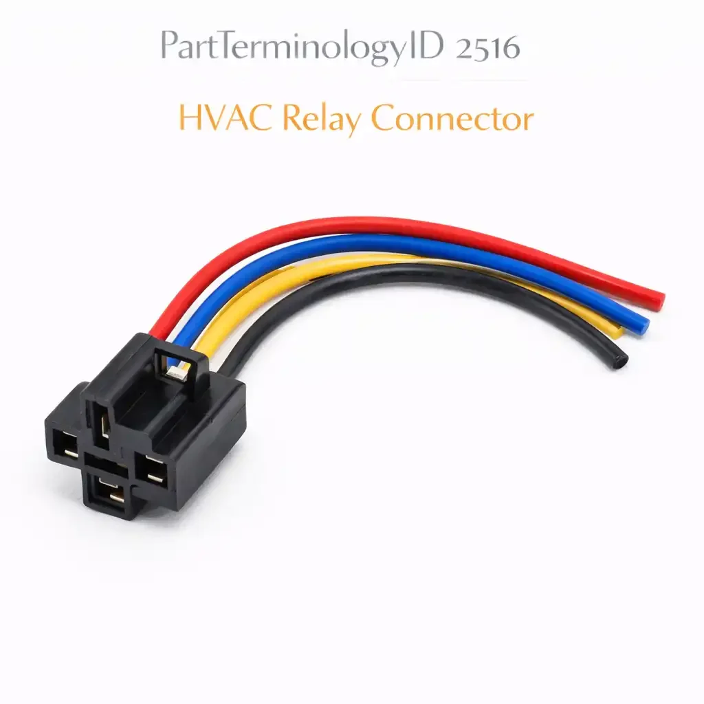
PartTerminologyID 2516, HVAC Relay Connector, is the wiring harness connector body that mates with the relay mounted in the HVAC control circuit, providing the electrical interface between the vehicle's HVAC wiring harness and the relay terminals that switch power to the blower motor, the compressor clutch, the condenser fan, or other HVAC system loads controlled through relay-switched circuits. That definition covers the function correctly. It does not specify the terminal count, the terminal pin gauge and current rating, the connector body housing design and keying, the terminal pin type, whether the terminals are female blade sockets accepting male blade relay terminals or male pin sockets accepting female pin relay terminals, the terminal material and plating, the connector lock type, whether the connector uses a primary lock tab, a secondary connector position assurance lock, or both, the wire seal type for weatherproof designs, the connector body color as a harness identification aid, the mating relay terminal spacing and pitch, the alternating relay terminal layout for asymmetric relay designs, the wire entry direction, whether the wires enter from the back of the connector inline with the mating axis or at a right angle, or the connector housing material and temperature rating. A listing under PartTerminologyID 2516 that provides vehicle year, make, and model without the terminal count, the terminal gauge rating, the connector body housing designation, and the mating relay terminal specification cannot be evaluated by any technician who has a heat-damaged or broken HVAC relay connector and is confirming the replacement before removing the wiring harness section that houses the original connector.
For sellers, PartTerminologyID 2516 serves a buyer who has confirmed that the HVAC fault traces to the connector rather than to the relay itself or to the control module. Heat damage at the connector from sustained high-current draw through corroded or undersized terminals, physical breakage of the connector lock tab from repeated relay removal, or terminal pin push-back from insertion force applied without the correct tool are the three most common connector failure modes that bring a buyer to this PartTerminologyID. All three produce symptoms that are visible at the connector: melted or discolored housing, a lock tab that will not retain the relay in the mating position, or a terminal that has retracted into the connector body and no longer contacts the relay pin.
The additional complexity specific to PartTerminologyID 2516 compared to a generic connector PartTerminologyID is the relay-mating geometry argument. An HVAC relay connector mates with a relay that has a standardized or proprietary terminal layout. ISO mini relays, ISO micro relays, and various OEM-specific relay designs have different terminal spacings, different terminal heights, and different keying configurations. A connector body with the correct terminal count but the wrong terminal spacing will not mate with the relay, and a connector with the correct body dimensions but the wrong keying will mate physically but will orient the terminals incorrectly against the relay pins, connecting the wrong circuits.
For sellers, the listing under this PartTerminologyID is only useful if it specifies the terminal count, the terminal gauge rating, the mating relay type, the connector body housing designation or equivalent, the lock type, and the wire entry direction. Without those six attributes, the listing cannot be confirmed by a technician who has the failed connector in hand and is matching the replacement to the relay it will mate with.
What the HVAC Relay Connector Does
Providing a serviceable interface between the harness and the relay
The HVAC relay connector allows the relay to be removed from the harness without cutting or splicing the harness wires. The connector mates with the relay terminals, locks in position, and provides a mechanically and electrically stable connection that withstands the vibration, thermal cycling, and occasional relay removal for testing that characterize normal HVAC service access.
The connector's retention system, typically a primary lock tab on the connector housing that engages the relay body and a secondary connector position assurance lock that prevents the primary tab from releasing unless the secondary lock is first disengaged, ensures the connector does not vibrate loose from the relay during vehicle operation. A connector with a broken primary lock tab will remain mated with the relay under static conditions but will disengage under vibration, producing an intermittent HVAC fault that clears when the connector is pressed firmly against the relay and recurs when the vehicle encounters road vibration.
Why heat damage at the HVAC relay connector is the most common failure mode
The HVAC relay controls the compressor clutch or the blower motor, both of which are high-current loads relative to most control circuit relays. The compressor clutch relay conducts the full compressor clutch engagement current, typically 3 to 8 amperes, through its switching contacts and through the connector terminals that carry the load circuit wires. The blower motor relay on high-speed settings may conduct 15 to 25 amperes through the load side terminals.
If the terminal pins are not fully seated in the connector housing, or if the terminal contact surfaces have corroded from moisture intrusion, the effective contact area between the terminal pin and the relay blade decreases and the contact resistance increases. The increased resistance produces heat at the contact interface proportional to the square of the current and the contact resistance. On a 20-ampere blower motor circuit, a contact resistance of 50 milliohms produces 20 watts of heat concentrated at the terminal face. That thermal load is sufficient to discolor the connector housing within hours of operation and to melt the housing around the terminal bore within days if the fault is not identified.
The heat damage that brings the buyer to PartTerminologyID 2516 is therefore a symptom of a terminal contact fault, and the connector replacement must be accompanied by a terminal inspection note directing the buyer to identify and correct the underlying cause of the contact resistance before installing the replacement connector.
The relay terminal layout and keying argument
ISO mini relays use a five-terminal layout with the terminals numbered 85, 86, 30, 87, and 87a according to the DIN standard for relay terminal identification. The terminal spacing and height are standardized across ISO mini relay designs from different manufacturers, which allows ISO mini relay connectors to be interchangeable across relay brands within the same terminal count and pitch. ISO micro relays use a similar five-terminal layout in a smaller body format with a different terminal pitch.
OEM-specific relay designs, including many used in HVAC control circuits on domestic and Asian market vehicles, use proprietary terminal layouts that are not interchangeable with ISO mini or ISO micro connector bodies. A connector specified for an ISO mini relay will not mate correctly with an OEM-proprietary relay even if the external housing dimensions appear similar.
The listing must state the compatible relay type by designation, not only by vehicle application, so the technician can confirm the connector matches the relay that is physically installed in the vehicle rather than assuming the relay is the OE type for the vehicle model.
The Specifications That Determine Correct Connector Fitment
Terminal count
The number of terminal positions in the connector body. ISO mini relay connectors are typically four-terminal (85, 86, 30, 87) or five-terminal (85, 86, 30, 87, 87a). State the count explicitly.
Terminal gauge rating
The current capacity of each terminal position in the connector body. Load circuit terminals carrying blower motor or compressor clutch current must be rated for the continuous load current at the operating temperature of the HVAC compartment.
Mating relay designation
ISO mini, ISO micro, or OEM-specific relay designation with the relay terminal pitch in millimeters. This is the primary fitment attribute that prevents connector-to-relay mismatch.
Connector body housing designation
The proprietary or industry-standard connector housing series designation used by the connector manufacturer. Enables direct cross-reference to the correct connector body in the technician's supplier catalog.
Lock type
Primary tab only, or primary tab with secondary connector position assurance lock. State the lock type and whether the secondary lock is a slide or a flip design.
Wire entry direction
Inline with mating axis or right-angle entry. Must match the harness routing geometry at the relay location.
Wire seal type
Unsealed for dry interior locations, single-wire seals for weatherproof applications such as under-hood HVAC relay positions.
Status in New Databases
PIES/PCdb: PartTerminologyID 2516, HVAC Relay Connector
PIES 8.0 / PCdb 2.0: No change
Top Return Scenarios
Scenario 1: "ISO mini connector sent for OEM-proprietary relay, terminal spacing mismatch, connector will not fully seat on relay"
The listing specified an HVAC relay connector by vehicle year, make, and model without stating the compatible relay designation. The vehicle's HVAC relay is an OEM-proprietary design with a terminal pitch of 6.3mm. The replacement connector is an ISO mini relay connector with a terminal pitch of 5.08mm. The connector partially seats on the relay but will not fully latch because the terminal pitch mismatch prevents the terminals from aligning with the relay blades. Two terminals seat and three do not.
Prevention language: "Compatible relay designation: [ISO mini / ISO micro / OEM-proprietary designation]. Terminal pitch: [X.X]mm. Verify the compatible relay designation and terminal pitch match the relay installed in your vehicle before ordering. HVAC relay connectors for ISO mini and OEM-proprietary relays are not interchangeable even when the terminal count is the same. A connector with the wrong terminal pitch will partially seat but will not fully latch and will not make reliable electrical contact at all terminal positions."
Scenario 2: "Terminal gauge rated for 10 amperes, blower motor high-speed current is 22 amperes, connector melted within one week of installation"
The replacement connector uses terminals rated for 10 amperes continuous. The blower motor on high-speed draws 22 amperes through the load circuit terminals. The replacement connector was installed over the original corroded relay without cleaning the relay blade terminals. Within one week, the load circuit terminals had reached their current limit and the connector housing had melted at the two load terminal positions.
Prevention language: "Load circuit terminal current rating: [X] amperes continuous. Verify the terminal current rating is adequate for the maximum load current of the HVAC circuit this connector serves before ordering. Clean the relay blade terminals with electrical contact cleaner before installing the replacement connector: a corroded relay blade in a new connector will reproduce the contact resistance heating that melted the original connector regardless of the replacement connector's current rating."
Scenario 3: "Right-angle wire entry connector sent for inline application, harness routing forces a bend at the connector body that cracks the housing within 2,000 miles"
The replacement connector has a right-angle wire entry. The harness routing at the relay location requires an inline connector where the wires exit straight back from the mating face. With the right-angle connector installed, the harness forces a sharp bend at the connector body to reach the relay in the panel. The repeated thermal cycling of the HVAC system causes the harness to flex at the connector body, cracking the housing at the right-angle bend point within 2,000 miles.
Prevention language: "Wire entry direction: [inline / right-angle]. Verify the wire entry direction matches the harness routing geometry at the relay location before ordering. An inline connector installed where a right-angle connector is required forces the harness to bend at the connector body. Repeated thermal cycling causes the harness to flex at this forced bend, cracking the connector housing and eventually breaking the wire insulation at the point of maximum flex stress."
What to Include in the Listing
Core essentials
PartTerminologyID: 2516
component: HVAC Relay Connector
terminal count (mandatory)
mating relay designation: ISO mini, ISO micro, or OEM-specific (mandatory)
terminal pitch in mm (mandatory)
terminal gauge rating in amperes per terminal position (mandatory)
connector body housing series designation (mandatory)
lock type: primary tab only or primary with secondary CPA (mandatory)
wire entry direction: inline or right-angle (mandatory)
wire seal type: unsealed or single-wire sealed (mandatory)
terminal pin type: female blade socket or male pin socket (mandatory)
terminal material and plating (mandatory)
connector body color (mandatory)
terminals included or connector body only (mandatory)
quantity: 1
Catalog Checklist for ACES/PIES Teams
PartTerminologyID = 2516
require mating relay designation as primary fitment attribute (mandatory)
require terminal pitch in mm (mandatory)
require terminal current rating per position (mandatory)
require terminal count (mandatory)
require lock type (mandatory)
require wire entry direction (mandatory)
require terminals included status (mandatory)
differentiate from relay (PartTerminologyID varies): the relay is the switching device; the connector is the harness interface to the relay; a broken connector lock tab or melted connector housing does not require relay replacement if the relay tests functional; the connector and the relay are separate components under separate PartTerminologyIDs
differentiate from blower motor relay and compressor clutch relay connectors where those are listed separately: some catalog implementations use separate PartTerminologyIDs for the blower motor relay connector and the compressor clutch relay connector; verify which HVAC relay position the listing addresses and state the circuit position in the listing
flag mating relay designation as the primary return driver: an ISO mini connector on an OEM-proprietary relay will partially seat and appear installed but will not make reliable contact at all terminal positions; the relay designation is the specification that prevents this from the ordering stage
flag terminal current rating as mandatory: a connector with undersized terminal current ratings installed on a high-current HVAC load circuit will melt the housing regardless of the connector body's dimensional correctness; the terminal current rating is the specification that prevents a repeat of the original heat damage failure
Final Take for PartTerminologyID 2516
HVAC Relay Connector (PartTerminologyID 2516) is the connector PartTerminologyID where the mating relay designation is the specification that prevents the most immediately detectable fitment failure, and where the terminal current rating is the specification that prevents the repeat of the heat damage that brought the buyer to this PartTerminologyID in the first place. A connector with the wrong relay designation will not fully seat. A connector with the correct designation but undersized terminal ratings installed over a corroded relay blade will melt its housing within days. Both failures are preventable by two attribute statements in the listing.
State the terminal count. State the mating relay designation and terminal pitch. State the terminal current rating per position. State the lock type. State the wire entry direction. State whether terminals are included. Include the relay blade cleaning note in the installation instructions. That is the same listing strategy as every other PartTerminologyID in this series: specific attributes at every level to become a listing buyers can act on without guessing. For PartTerminologyID 2516, the relay designation and the terminal current rating are the two attributes that determine whether the replacement connector fits the relay correctly and survives the load it carries.