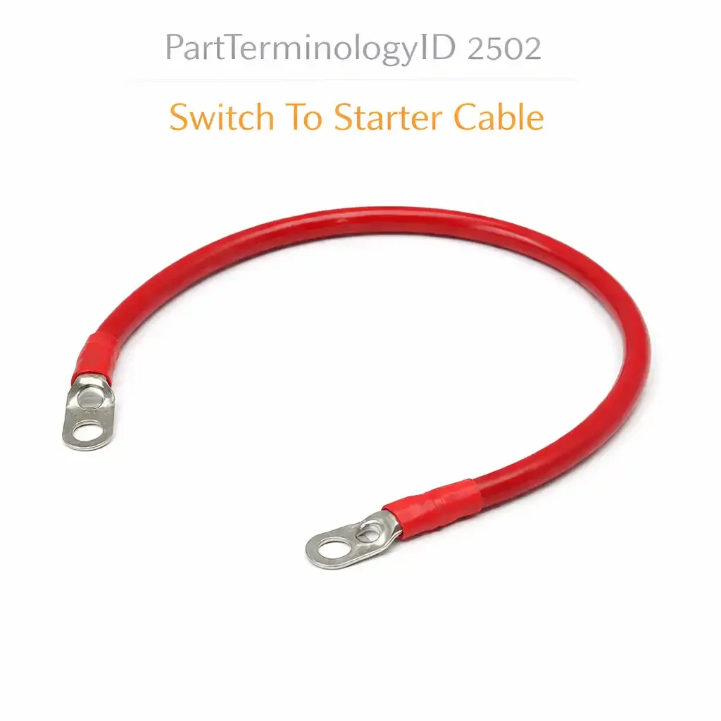
Switch To Starter Cable (PartTerminologyID 2502): Why Control Circuit Gauge, Switch Terminal Type, and Length Prevent Engagement Failures
Written by Arthur Simitian | PartsAdvisory
PartTerminologyID 2502, Switch To Starter Cable, is the small-gauge insulated conductor that carries the low-current control signal from the ignition switch, the neutral safety switch, the clutch interlock switch, or the starter relay to the S terminal on the starter motor solenoid, energizing the solenoid coil that pulls the plunger to engage the starter drive pinion with the ring gear and close the main solenoid contacts that connect the battery cable to the starter motor armature. That definition covers the function correctly and establishes the critical distinction from PartTerminologyID 2501, the Starter Cable, which carries the full cranking current to the solenoid main terminal. The switch to starter cable carries only the control signal current to the solenoid trigger terminal, typically 3 to 10 amperes, not the 150 to 800 amperes of the cranking circuit. A listing under PartTerminologyID 2502 that conflates the switch-to-starter control wire with the main starter cable will direct buyers to an undersized control wire when they need the main cranking cable, or to an oversized cranking cable when they need only the low-current control wire.
For sellers, PartTerminologyID 2502 serves a buyer who has confirmed that the starter does not engage when the ignition is turned to the start position, has verified that the battery and the main starter cable have adequate voltage, and has traced the fault to the control circuit between the ignition switch output and the solenoid S terminal. The control circuit fault may be an open wire from a chafed or broken conductor, a corroded terminal at the solenoid S terminal pin, a corroded terminal at the ignition switch output connector, or a failed neutral safety switch or clutch interlock switch that prevents the control signal from reaching the solenoid. If the wire itself is the failed component, PartTerminologyID 2502 is the correct sourcing target.
The additional complexity specific to PartTerminologyID 2502 compared to 2500 and 2501 is the routing path through switches and relays. The switch to starter cable is not a single uninterrupted wire from the ignition switch to the solenoid S terminal on most modern vehicles. It passes through the neutral safety switch on automatic transmission vehicles, through the clutch interlock switch on manual transmission vehicles, and in many cases through a starter relay that interposes between the ignition switch output and the solenoid S terminal. The listing must specify which segment of the control circuit it covers: the full ignition-switch-to-solenoid run, the relay-output-to-solenoid segment only, or another defined section of the circuit, so the buyer can confirm the replacement covers the failed section.
For sellers, the listing under this PartTerminologyID is only useful if it specifies the wire gauge, the control circuit segment the cable covers, the terminal type at the solenoid S terminal end, the terminal type at the switch or relay output end, and the cable length. Without those five attributes, the listing cannot distinguish the control wire from the cranking cable to a buyer who is unfamiliar with the cranking circuit architecture and risks ordering the wrong component for the wrong circuit position.
What the Switch To Starter Cable Does
Energizing the solenoid coil to initiate engagement
When the ignition is turned to the start position, the ignition switch routes battery voltage through the neutral safety switch or clutch interlock switch, and in some configurations through a starter relay, to the solenoid S terminal. The voltage at the S terminal energizes the solenoid pull-in and hold-in coils. The pull-in coil draws approximately 20 to 40 amperes momentarily to pull the plunger from its rest position. The hold-in coil draws approximately 5 to 10 amperes to maintain the plunger in the engaged position while the starter motor cranks the engine. The switch to starter cable must carry these currents without excessive voltage drop, because the solenoid coils require a minimum voltage at the S terminal to develop adequate pull-in force.
A switch to starter cable with a corroded terminal at the solenoid S terminal pin, a chafed insulation break causing partial conductor contact with chassis ground, or a broken conductor strand that increases the wire resistance will reduce the voltage at the S terminal below the solenoid coil's minimum operating voltage. The symptom is a no-crank condition: the ignition is turned to start, the dash lights remain on indicating adequate battery voltage, but the starter does not engage and no click from the solenoid is heard. This symptom pattern distinguishes a control circuit fault from a main cranking circuit fault, where the solenoid click is heard but the starter motor does not crank or cranks slowly.
The neutral safety switch and clutch interlock in the control circuit path
On automatic transmission vehicles, the neutral safety switch is wired in series with the switch to starter cable between the ignition switch output and the solenoid S terminal. The neutral safety switch opens the control circuit in all transmission range positions except Park and Neutral, preventing the engine from being started in gear. A failed open neutral safety switch produces the same no-crank symptom as a broken switch to starter cable. Confirming that the wire itself is the failed component rather than the switch requires measuring continuity through the switch in the correct transmission range before ordering a replacement wire.
On manual transmission vehicles, the clutch interlock switch performs the same function, opening the control circuit unless the clutch pedal is fully depressed. A failed clutch interlock switch that remains open regardless of pedal position produces the no-crank symptom and must be diagnosed before replacing the switch to starter cable.
The listing should include a diagnostic note directing the buyer to confirm the wire is the failed component rather than the switch in the control circuit path before ordering.
Gauge and voltage drop in the control circuit
The switch to starter cable is a low-current control wire, typically 14 AWG to 18 AWG depending on the vehicle design, compared to the 2 AWG to 2/0 AWG of the main starter cable. Its gauge is determined by the solenoid pull-in current requirement and the acceptable voltage drop across the control circuit at that current. A wire that is too small in gauge for the pull-in current will produce a voltage drop at the S terminal that prevents the solenoid from developing adequate pull-in force, producing an intermittent engagement failure that worsens as the wire corrodes and its resistance increases.
The listing must state the wire gauge so the buyer can confirm it matches the OE specification. Substituting a smaller gauge wire than the OE specification to reduce cost or because the correct gauge is unavailable will produce a voltage drop that results in intermittent no-start conditions that are difficult to diagnose because the symptom appears only when the wire's resistance has increased enough from heat cycling and corrosion to drop the S terminal voltage below the solenoid minimum.
The Specifications That Determine Correct Fitment
Wire gauge
In AWG. The control circuit gauge is substantially smaller than the cranking circuit gauge. State the AWG and note that this is the control wire, not the main cranking cable.
Control circuit segment
Full ignition-switch-to-solenoid run, relay-output-to-solenoid segment, or neutral-safety-switch-output-to-solenoid segment. State the segment explicitly.
Solenoid S terminal connector type
The solenoid S terminal is typically a female spade connector, a weatherproof connector body, or a ring terminal depending on the solenoid design. State the connector type and the terminal pin size.
Switch or relay end terminal type
Spade, blade, ring terminal, or weatherproof connector. State the type and size at the ignition switch, relay, or safety switch end.
Cable length
In millimeters. For vehicles where the control wire routing passes through multiple switch positions, state the routed length including switch connectors.
Insulation material and temperature rating
As with all starter circuit cables, confirm that the insulation rating is adequate for the routing environment.
Status in New Databases
PIES/PCdb: PartTerminologyID 2502, Switch To Starter Cable
PIES 8.0 / PCdb 2.0: No change
Top Return Scenarios
Scenario 1: "Control wire ordered when main cranking cable needed, wire gauge far too small for solenoid main terminal"
The listing was ambiguous about whether the cable was the control wire to the S terminal or the main cranking cable to the B+ terminal. The buyer needed the main cranking cable. An 18 AWG control wire arrived. The buyer attempted to connect it to the solenoid main terminal stud, where the 18 AWG lug is far smaller than the 10mm main terminal stud, and recognized immediately that the wrong cable had arrived.
Prevention language: "This listing covers the Switch To Starter Cable, the low-current control wire from the [ignition switch / starter relay] to the solenoid S trigger terminal. Wire gauge: [X] AWG. This is NOT the main starter cranking cable that connects to the solenoid main power terminal. The main starter cable (PartTerminologyID 2501) carries 150 to 800 amperes of cranking current and is a substantially larger gauge conductor. Verify which cable position you need before ordering."
Scenario 2: "Neutral safety switch in control circuit not diagnosed before ordering wire, wire replaced, fault persists"
The buyer diagnosed a no-crank condition and traced the fault to the control circuit between the ignition switch and the solenoid S terminal. The listing for the switch to starter cable did not include a diagnostic note about the neutral safety switch in the circuit path. The buyer replaced the wire. The neutral safety switch was failed open in all transmission range positions. The no-crank condition persisted after the wire replacement and the wire was returned as the wrong part.
Prevention language: "Before ordering: confirm that the wire itself is the failed component rather than the neutral safety switch or clutch interlock switch in the control circuit. On automatic transmission vehicles, measure continuity through the neutral safety switch with the transmission in Park and Neutral. On manual transmission vehicles, measure continuity through the clutch interlock switch with the clutch pedal fully depressed. If the switch shows no continuity in the correct position, replace the switch rather than the wire. Replace the wire if continuity through the switch is confirmed but the wire shows an open circuit or elevated resistance between the switch output terminal and the solenoid S terminal."
Scenario 3: "Relay-output-to-solenoid segment needed, full ignition-switch-to-solenoid cable received, excess length and wrong intermediate connectors"
The vehicle has a starter relay. The failed segment is the 250mm wire from the relay output terminal to the solenoid S terminal. The listing stated a switch to starter cable for the vehicle without specifying the segment. The full ignition-switch-to-solenoid cable arrived, approximately 1,100mm with connectors for the ignition switch output, the neutral safety switch, and the relay input. The relay-output-to-solenoid segment is a separately routed wire that connects at a different position in the engine bay.
Prevention language: "Control circuit segment: [relay output terminal to solenoid S terminal, [X]mm / complete ignition switch to solenoid S terminal, [X]mm]. This vehicle has a starter relay that divides the control circuit. Verify which segment of the control circuit is failed before ordering. The relay-output-to-solenoid segment and the complete ignition-switch-to-solenoid cable have different lengths and different connector configurations at each end."
What to Include in the Listing
Core essentials
PartTerminologyID: 2502
component: Switch To Starter Cable
explicit statement that this is the low-current control wire, not the main cranking cable (mandatory)
control circuit segment covered (mandatory)
wire gauge in AWG (mandatory)
solenoid S terminal connector type and pin size (mandatory)
switch or relay end terminal type and size (mandatory)
cable length in mm (mandatory)
insulation material and temperature rating (mandatory)
neutral safety switch and clutch interlock diagnostic note (mandatory)
quantity: 1
Catalog Checklist for ACES/PIES Teams
PartTerminologyID = 2502
require explicit low-current control wire designation in the listing to prevent confusion with main cranking cable (mandatory)
require control circuit segment: full run or relay-to-solenoid segment (mandatory)
require wire gauge in AWG (mandatory)
require solenoid S terminal connector type (mandatory)
require switch or relay end terminal type (mandatory)
require cable length (mandatory)
require neutral safety switch and clutch interlock diagnostic note (mandatory)
differentiate from starter cable (PartTerminologyID 2501): the starter cable carries 150 to 800 amperes of cranking current to the solenoid main B+ terminal; the switch to starter cable carries 5 to 40 amperes of control signal current to the solenoid S terminal; the two cables are different gauges, different terminal types, and connect to different terminals on the solenoid; they must not be listed under the same PartTerminologyID or described in the same terms
differentiate from neutral safety switch: the neutral safety switch is a component in the control circuit path; the switch to starter cable is the wire that passes through that circuit; a failed switch requires switch replacement; a failed wire requires cable replacement; the listing must direct buyers to diagnose which component is failed before ordering either
flag control wire versus cranking cable confusion as the primary return driver: a buyer who needs the main cranking cable and receives a 16 AWG control wire will recognize the error immediately at installation; the clarification statement in the listing is the single most important text element for preventing this return
Final Take for PartTerminologyID 2502
Switch To Starter Cable (PartTerminologyID 2502) is the cranking circuit PartTerminologyID where the distinction from PartTerminologyID 2501 must be stated explicitly in the listing because the two components connect to the same physical device, the starter solenoid, at two different terminals that carry currents differing by a factor of 50 to 100. A buyer who is unfamiliar with solenoid terminal nomenclature will not know from the PartTerminologyID alone whether this listing covers the control wire to the S terminal or the cranking cable to the B+ terminal. The clarification statement is not optional: it is the primary listing element that determines whether the buyer orders the correct component on the first attempt.
State the control wire designation explicitly. State the control circuit segment. State the gauge in AWG with the current level it carries. State the solenoid S terminal connector type. State the switch or relay end terminal type. State the length. Include the neutral safety switch and clutch interlock diagnostic note. That is the complete specification for a buyer who has confirmed the wire is the failed component in the control circuit and needs only the dimensional and terminal confirmation before placing the order.