Alternator Resistor (PartTerminologyID 2460): Why Resistance Value and Circuit Position Determine Excitation Function
Written by Arthur Simitian | PartsAdvisory
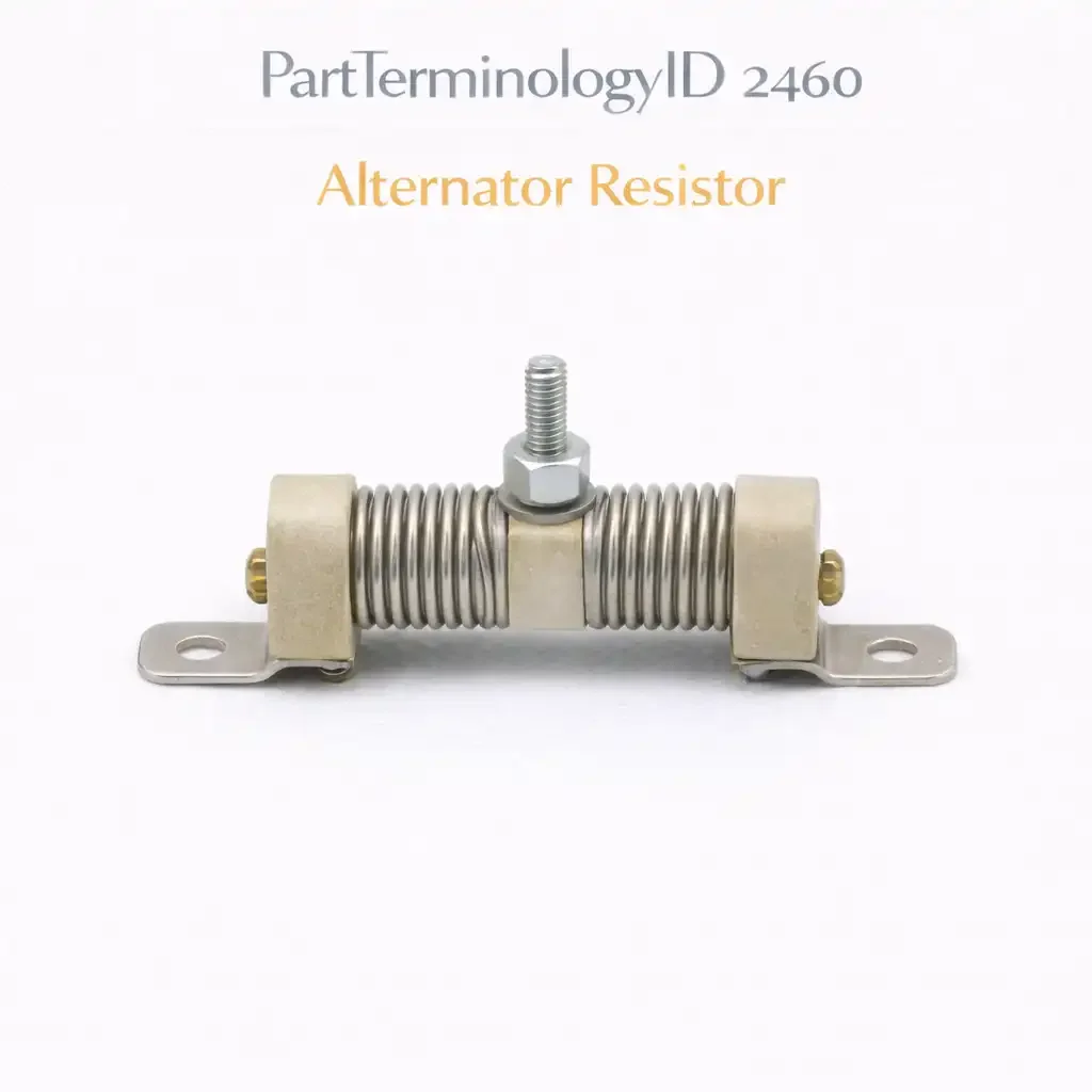
PartTerminologyID 2460, Alternator Resistor, is the fixed resistor in the alternator excitation circuit that limits the initial field current supplied from the battery to the voltage regulator and rotor field winding during alternator startup, preventing the full battery voltage from being applied directly to the field winding before the alternator reaches self-sustaining output, and in some designs providing a parallel path for the charge warning light circuit that determines whether the warning light illuminates correctly when the alternator is not charging. That definition covers the function correctly. It does not specify the resistance value in ohms, the power rating in watts, the circuit position, whether the resistor is in series with the excitation circuit or in parallel with the charge warning light, the physical form factor, whether the resistor is a discrete wire-wound component, a resistor embedded in a wiring harness connector, or a resistor integrated into the instrument cluster circuit board, the terminal type and connection method, the alternator and vehicle application the resistor is designed for, or whether a failed resistor is producing a no-charge condition from an open-circuit resistor that has interrupted the excitation path, or a charge warning light that remains on from a short-circuit resistor that has bypassed the lamp circuit. A listing under PartTerminologyID 2460 that provides vehicle year, make, and model without the resistance value, the power rating, and the circuit position cannot be evaluated by a technician who has confirmed the resistor as the failed component.
For sellers, PartTerminologyID 2460 serves the narrowest buyer population in the alternator sub-component series. The alternator resistor is present on a subset of older vehicle platforms, predominantly domestic designs from the 1970s through the early 1990s that used external voltage regulators and discrete excitation circuit components. On most modern vehicles, the excitation resistor function is performed internally by the voltage regulator circuit and there is no separately replaceable excitation resistor. A buyer ordering under this PartTerminologyID has typically confirmed the resistor as the failed component through a resistance measurement and has identified the part from a wiring diagram rather than from a parts catalog vehicle fitment search. The listing must serve that technically specific buyer with resistance value and circuit position as the primary search confirmation attributes.
What the Alternator Resistor Does
Limiting initial field current during excitation
When the ignition is switched on before the engine is started, the charge warning light circuit supplies a small initial field current from the battery through the warning light bulb and the excitation resistor to the voltage regulator and the field winding. This current magnetizes the rotor field winding sufficiently to allow the alternator to begin generating output when the engine starts. Once the alternator reaches self-sustaining output, the diode trio supplies field current internally and the initial excitation path through the warning light and resistor carries negligible current.
The resistor limits the initial field current to prevent excessive current draw through the warning light bulb, which would shorten the bulb life and potentially damage the instrument cluster circuit. It also prevents full battery voltage from appearing across the field winding terminals before the regulator is active, which on some designs could cause the regulator to receive an unregulated voltage spike during startup.
The charge warning light parallel resistor
On some designs, the alternator resistor is wired in parallel with the charge warning light rather than in series with the excitation circuit. In this configuration, the resistor provides a current path that keeps a small field current flowing to the regulator even if the charge warning light bulb burns out. Without the parallel resistor, a burned-out warning light bulb would interrupt the excitation circuit entirely, preventing the alternator from starting to charge and producing a no-charge condition that the driver cannot attribute to a bulb failure because the warning light is dark rather than illuminated.
The parallel resistor therefore serves a redundancy function: it ensures the alternator continues to charge even when the warning light is burned out. A failed open-circuit parallel resistor combined with a burned-out warning light bulb produces a no-charge condition that presents as an alternator failure but is actually two simultaneous minor component failures.
Failure modes and diagnostic signatures
An open-circuit resistor in the series excitation path prevents the initial field current from reaching the regulator and field winding, preventing the alternator from starting to charge. The symptom is a no-charge condition from startup with the charge warning light illuminated, identical to a complete alternator failure. The distinction is confirmed by measuring resistance across the resistor terminals: an open-circuit resistor will read infinite ohms rather than the design resistance value.
A short-circuit resistor in the parallel warning light position bypasses the warning light bulb entirely, keeping the warning light off regardless of the alternator's charging state. The symptom is a charge warning light that does not illuminate even when the alternator is not charging, which can prevent the driver from detecting a genuine charging system failure.
The Specifications That Determine Correct Fitment
Resistance value
In ohms. The primary specification. Must match the OE value to maintain the correct field current limiting function and the correct warning light brightness.
Power rating
In watts. The resistor must dissipate the power produced by the excitation current without overheating. Undersized power rating produces thermal failure of the resistor body.
Circuit position
Series excitation resistor or parallel warning light resistor. The two positions have different resistance values and different failure mode consequences. State the circuit position explicitly.
Terminal type and connection method
Wire-wound with spade terminals, inline harness resistor, or board-mounted component. Must match the original installation method.
Alternator and vehicle application
State the specific vehicle platform and alternator model the resistor is calibrated for.
Status in New Databases
PIES/PCdb: PartTerminologyID 2460, Alternator Resistor
PIES 8.0 / PCdb 2.0: No change
Top Return Scenarios
Scenario 1: "Resistance value incorrect, warning light stays on at all engine speeds"
The replacement resistor has a resistance value of 55 ohms. The OE specification is 75 ohms. The lower resistance value allows more current through the excitation circuit than the regulator's input stage expects, causing the regulator to interpret the elevated current as an undercharge condition and illuminating the warning light continuously regardless of alternator output voltage.
Prevention language: "Resistance value: [X] ohms. Power rating: [X] watts. Verify the resistance value matches the OE specification for your vehicle before ordering. A resistor with a lower resistance than the OE value will allow excess current into the regulator input stage, producing a continuous charge warning light regardless of actual alternator output."
Scenario 2: "Series resistor ordered for parallel warning light position, alternator stops charging when bulb burns out"
The listing specified an alternator resistor by vehicle without stating the circuit position. The buyer needed the parallel warning light resistor. A series excitation resistor arrived. The series resistor was installed in the parallel position across the warning light. Its resistance value is too high for the parallel position and it does not provide adequate redundant field current when the warning light bulb burns out. When the bulb burned out, the alternator stopped charging.
Prevention language: "Circuit position: [series excitation / parallel warning light]. The series excitation resistor and the parallel warning light resistor for the same vehicle have different resistance values and are not interchangeable. State the circuit position when ordering. Installing a series resistor in the parallel position will not maintain alternator charging when the warning light bulb burns out."
Catalog Checklist for ACES/PIES Teams
PartTerminologyID = 2460
require resistance value in ohms (mandatory)
require power rating in watts (mandatory)
require circuit position: series excitation or parallel warning light (mandatory)
require terminal type and connection method (mandatory)
require vehicle platform and alternator model designation (mandatory)
differentiate from voltage regulator (PartTerminologyID varies): the voltage regulator controls the field current continuously during alternator operation; the alternator resistor limits the initial excitation current during startup only; a regulator failure produces a charging voltage outside the design range; a resistor failure produces a no-charge or warning light malfunction at startup
flag resistance value as mandatory primary attribute: a resistor listing without the resistance value is a specification the buyer cannot verify; the resistance value is the only attribute that can be confirmed with a multimeter before installation
flag circuit position as mandatory: the series and parallel positions have different resistance values and different failure mode consequences; they are not interchangeable and must be specified separately
Final Take for PartTerminologyID 2460
Alternator Resistor (PartTerminologyID 2460) is the most narrowly applicable listing in the alternator sub-component series. The buyer population is limited to older vehicle platforms with discrete external excitation circuits, and the buyer has almost certainly confirmed the resistor as the failed component through a resistance measurement before searching. The listing's job is to confirm the resistance value, the power rating, and the circuit position so the buyer can place the order with confidence. State those three attributes prominently. A listing that does not state the resistance value has omitted the only specification the buyer can independently verify with a multimeter before installation.