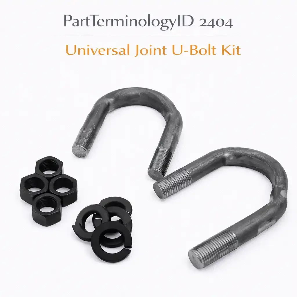
Universal Joint U-Bolt Kit (PartTerminologyID 2404): Where U-Joint Series, U-Bolt Dimensions, and Nut Specification Determine Whether the Bearing Cup Stays Clamped at Full Torque
Written by Arthur Simitian | PartsAdvisory
PartTerminologyID 2404, Universal Joint U-Bolt Kit, is the hardware set that clamps the U-joint bearing cups into the saddle yoke of a driveshaft or transfer case output connection using a U-shaped bolt rather than a snap ring. That definition locates the kit at the bearing cup retention interface on saddle-type yokes. It does not specify the U-joint series the kit is designed for, the U-bolt inner width between the legs, the U-bolt leg length, the U-bolt thread diameter and pitch, the U-bolt wire or rod diameter, whether the kit uses two U-bolts per bearing cup pair or one U-bolt per cup, the nut specification including thread class and whether the nuts are prevailing torque locknuts or standard hex nuts, the clamp plate specification if a clamp plate is included, what the torque specification is for the nuts, whether the kit covers one cup pair or a complete four-cup U-joint assembly, the U-bolt material and coating, or whether the bearing cups in the application have a flat-bottom seat for U-bolt clamping or a round outer surface that is incompatible with U-bolt retention. A listing under PartTerminologyID 2404 that specifies the U-joint series without the U-bolt inner width, leg length, thread specification, nut type, and quantity cannot be evaluated by any technician who has the yoke on the bench and is sourcing the replacement hardware before pressing the new U-joint.
For sellers, PartTerminologyID 2404 occupies a specific retention hardware position that is distinct from both the C-clip post (PartTerminologyID 2400) and the strap kit that covers a third retention method. U-bolt retention is most common on slip yokes at the rear of the transmission tail shaft, on transfer case output yokes, on truck rear axle companion flange connections, and on heavy-duty commercial vehicle propshaft connections where the higher torque capacity of the U-bolt clamping arrangement is preferred over snap ring retention. The buyer population for this PartTerminologyID is therefore concentrated in the truck and commercial vehicle service market, where propshaft U-joint service is a routine maintenance item on a scheduled basis rather than an event-driven repair.
The additional complexity specific to this PartTerminologyID is that the U-bolt kit is almost never a standalone purchase: it is always purchased alongside or in the same order as a replacement U-joint, because the U-bolts are deformed during removal when the old joint is pressed out and are not reusable. A listing that does not cross-reference the compatible U-joint series and confirm that the U-bolt dimensions match the bearing cup flat dimensions for that series will be returned by a technician who discovers at installation that the U-bolt inner width does not match the bearing cup flat width, even though the series designation matched.
For sellers, the listing under this PartTerminologyID is only useful if it specifies the compatible U-joint series, the U-bolt inner width, the leg length, the thread diameter and pitch, the nut specification, the clamp plate specification, the torque specification, and the quantity. Without those eight attributes, the listing cannot confirm the U-bolt dimensions against the bearing cup flat dimensions that the technician has already measured before ordering.
What the Universal Joint U-Bolt Kit Does
Clamping the bearing cup flat against the saddle yoke seat
A saddle yoke has two U-shaped saddle cutouts, one on each side of the yoke fork, where the flat-bottom bearing cups of the U-joint seat directly. The U-bolt straddles the bearing cup and the yoke saddle, with the two legs of the U passing through holes in a clamp plate or directly through holes in the yoke ears, and the nuts tighten from below to draw the bearing cup flat against the yoke saddle surface.
The clamping force is the product of the nut torque and the U-bolt thread pitch efficiency. The bearing cup flat surface must be in full contact with the yoke saddle surface for the clamping force to be distributed correctly. A bearing cup with a rounded outer surface rather than a machined flat will rock in the saddle rather than seating flush, and the U-bolt clamping force will be concentrated at the cup edges rather than distributed across the full flat surface.
The U-bolt retention method provides higher clamping force than snap ring retention because the clamping load acts across the full flat surface of the bearing cup rather than at a thin groove interface. This higher clamping force is why U-bolt retention is specified for higher-torque applications where snap ring retention would produce groove wear and eventual cup walking under the cyclic loads.
Why U-bolts are single-use components
When a U-joint is removed from a saddle yoke, the U-bolts must be loosened and removed. The U-bolt rod is a tensioned fastener that has been torqued to its design specification and has stretched slightly under the tension. A torque-to-yield U-bolt that has been torqued to specification cannot be retorqued to achieve the same tension because the rod has already yielded at the original torque. Reusing a stretched U-bolt with a new U-joint will not achieve the original clamping force, and the undertensioned U-bolt will allow the bearing cup to move under the torque loads of driveshaft operation.
Even on U-bolts that are not torque-to-yield by design, the nut seats and the U-bolt threads accumulate deformation from the first torque cycle that prevents accurate retorquing on subsequent installations. The standard practice in professional driveshaft service is to replace all U-bolts and nuts at every U-joint service event, regardless of the visible condition of the removed hardware.
The listing must state that U-bolts are single-use fasteners and must confirm the kit includes sufficient U-bolts and nuts for a complete installation without reusing any hardware from the previous joint.
The clamp plate and its dimensional relationship to the U-bolt
Some U-bolt retention yoke designs include a separate clamp plate that spans the bearing cup flat and provides the load distribution surface against which the U-bolt legs bear. The clamp plate has two holes that accept the U-bolt legs and a flat underside that contacts the bearing cup flat surface. The clamp plate converts the two-point U-bolt leg loads into a distributed clamping force across the bearing cup flat.
The clamp plate dimensions are specific to the bearing cup flat dimensions: the plate must cover the full flat surface without overhanging the cup edges in a way that contacts the yoke saddle walls. A clamp plate that is too narrow concentrates the clamping load on a smaller contact area and may allow the cup to rock under load. A clamp plate that is too wide contacts the yoke saddle walls and prevents the cup from seating fully against the saddle face.
The listing must state whether a clamp plate is included, its dimensions, and whether it is the correct plate for the bearing cup flat dimensions of the specified U-joint series.
The nut specification and the torque sequence
The nuts on a U-joint U-bolt kit are the final torque-applying element in the retention system. Two nut types are common: standard hex nuts and prevailing torque locknuts. Standard hex nuts require a thread locking compound applied to the threads before installation to prevent loosening from the vibration of driveshaft operation. Prevailing torque locknuts use a nylon insert or a distorted thread section to provide self-locking resistance without additional compound.
The torque sequence matters as much as the torque value. On a four-point U-bolt retention design where two U-bolts clamp one bearing cup pair, the nuts must be tightened in a cross pattern, similar to wheel lug nuts, to draw the clamp plate or bearing cup flat uniformly against the saddle without tilting the cup in the saddle. Tightening both nuts on one U-bolt before touching the other U-bolt will tilt the cup and concentrate the clamping load on one edge, which is functionally equivalent to using a clamp plate that is too narrow.
The torque specification must be stated in the listing in both foot-pounds and Newton-meters, and the cross-pattern torque sequence must be noted in the installation instruction.
The bearing cup flat width and its relationship to the U-bolt inner width
The U-bolt inner width, the distance between the inside faces of the two U-bolt legs at the saddle contact depth, must match the bearing cup flat width for the U-joint series. If the U-bolt is too wide, the legs do not contact the clamp plate or the yoke holes at the designed angle, and the clamping force direction is not perpendicular to the bearing cup flat. If the U-bolt is too narrow, the legs bear against the sides of the bearing cup rather than spanning it cleanly, damaging the cup outer surface and preventing full cup seating in the saddle.
The U-bolt inner width specification must be stated in the listing alongside the bearing cup flat width for the compatible U-joint series. A technician who has the bearing cup in hand can measure the flat width and confirm the U-bolt inner width is correct before installation.
Thread diameter, pitch, and grade
The U-bolt thread is the interface between the U-bolt and the nut that generates the clamping force. The thread diameter and pitch determine the nut that must be used and the torque required to achieve the specified tension. The thread grade determines the maximum tension the U-bolt can sustain without yielding.
A U-bolt with a lower thread grade than the application requires will yield at a lower torque than specified, producing a clamping force lower than the design value even when the nut is torqued correctly. A common error is substituting a hardware-store U-bolt of Grade 5 for an OE-specification Grade 8 U-bolt, achieving the torque specification at a lower actual clamping force because the Grade 5 material has already yielded before the torque target is reached.
The listing must state the thread diameter, pitch, and grade, and must note that Grade 5 hardware is not an acceptable substitute for a Grade 8 specification.
The Specifications That Determine Correct Kit Fitment
Compatible U-joint series
The U-joint series designation determines the bearing cup outer diameter, the bearing cup flat width, and the cup length for which the U-bolt dimensions are sized. The series designation is the primary fitment attribute alongside the U-bolt dimensions because the same U-bolt dimensions may appear across multiple series if the bearing cup flat dimensions are shared between series.
U-bolt inner width
The distance between the inside faces of the legs at the bearing cup flat contact depth, in millimeters. Must match the bearing cup flat width for the series within a specified tolerance.
U-bolt leg length
The distance from the base of the U to the end of the threaded section, in millimeters. Must be sufficient to pass through the yoke holes or clamp plate holes, engage the full thread length of the nut, and leave adequate thread engagement beyond the nut face.
U-bolt rod diameter
The diameter of the U-bolt rod in millimeters. Determines the U-bolt thread root diameter, the cross-sectional strength, and the hole diameter required in the yoke or clamp plate.
Thread diameter and pitch
State in both SAE (fractional inch) and metric where dual standards exist in the application. State the thread class for engagement confirmation.
Thread grade
Grade 5 or Grade 8 SAE, or equivalent metric property class. Mandatory because the clamping force is determined by the thread grade as much as by the torque value.
Nut type
Standard hex nut requiring thread locking compound, or prevailing torque locknut. State which is included.
Clamp plate inclusion and dimensions
Whether a clamp plate is included, the plate length and width in millimeters, and the hole spacing in millimeters.
Torque specification
In foot-pounds and Newton-meters. Include the cross-pattern torque sequence note.
Quantity
Number of U-bolts, nuts, and clamp plates in the kit. State whether the kit covers one bearing cup pair (two U-bolts, four nuts) or a complete U-joint assembly (four U-bolts, eight nuts) for designs that use one U-bolt per cup.
Why This Part Generates Returns
Buyers order the wrong universal joint U-bolt kit because:
the U-bolt inner width is not stated and the legs do not span the bearing cup flat correctly for the series
the thread grade is not stated and a Grade 5 substitute is used where Grade 8 is specified, producing an undertensioned clamp at the correct torque value
the nut type is not specified and standard hex nuts are used without thread locking compound, backing off under driveshaft vibration within the first service interval
the clamp plate dimensions are not stated and the plate overhangs the cup edges and contacts the yoke saddle walls
the kit covers only one bearing cup pair and the buyer needed a complete four-cup assembly kit, leaving two cups unretained mid-installation
the U-bolt leg length is not stated and the legs do not provide sufficient thread engagement for the specified nut torque
the bearing cup is a round-outer-surface design incompatible with U-bolt retention and the buyer ordered U-bolt hardware for a snap ring yoke application
Status in New Databases
PIES/PCdb: PartTerminologyID 2404, Universal Joint U-Bolt Kit
PIES 8.0 / PCdb 2.0: No change
Top Return Scenarios
Scenario 1: "U-bolt inner width too wide, legs contact clamp plate at incorrect angle, clamping force direction off-perpendicular"
The kit inner width is 3mm wider than the bearing cup flat width. When the U-bolt is positioned over the clamp plate, the legs contact the plate holes at an angle rather than perpendicularly. The nuts draw the U-bolt at an angle rather than straight down, producing a clamping force vector that is not perpendicular to the bearing cup flat surface. The cup seats unevenly in the saddle with one edge lower than the other. The propshaft develops a low-frequency clunk at low speed from the cup rocking in the saddle under load direction changes.
Prevention language: "U-bolt inner width: [X.X]mm. Bearing cup flat width for this series: [X.X]mm. The U-bolt inner width must match the bearing cup flat width within [X.X]mm tolerance. A U-bolt that is wider than the cup flat will contact the clamp plate at an angle rather than perpendicularly, producing an off-axis clamping force that seats the cup unevenly in the saddle."
Scenario 2: "Grade 5 U-bolts, Grade 8 specified, clamping force insufficient at correct torque, cup moved within 10,000 miles"
The application specifies Grade 8 U-bolts with a clamping force torque of 18 foot-pounds. The buyer substituted a Grade 5 kit from a hardware supplier. At 18 foot-pounds, the Grade 5 U-bolt rod had already yielded past its elastic limit. The actual tension in the rod was lower than the Grade 8 tension at the same torque because the Grade 5 material's yield point is lower. The bearing cups began moving axially in the saddles within 10,000 miles as the rod tension relaxed further after initial yield.
Prevention language: "U-bolt grade: [Grade 8 / SAE J429 Grade 8 or equivalent]. Do not substitute Grade 5 U-bolts for this application. Grade 5 U-bolts yield at a lower torque than Grade 8 and will produce a lower clamping force at the same torque specification. A Grade 5 U-bolt torqued to the Grade 8 specification has already yielded and will relax further after installation, producing progressive bearing cup movement under driveshaft torque loads."
Scenario 3: "Standard hex nuts, no thread locking compound applied, nuts backed off under vibration within 8,000 miles"
The kit included standard hex nuts without prevailing torque features. The installation instructions did not note the thread locking compound requirement. The technician assembled the U-bolt kit without applying locking compound. Under the vibration of driveshaft operation at highway speed, the standard hex nuts backed off incrementally. At 8,000 miles, one nut had loosened enough to allow the bearing cup to begin rocking in the saddle. The resulting vibration increased rapidly until the cup separated from the saddle at highway speed.
Prevention language: "Nut type: [prevailing torque locknut / standard hex nut requiring thread locking compound]. If standard hex nuts are used, apply medium-strength thread locking compound to the U-bolt threads before installing the nuts. Standard hex nuts without thread locking compound will back off under the vibration of driveshaft operation. Do not use standard hex nuts without locking compound on any U-bolt U-joint application."
Scenario 4: "Kit covers one cup pair, buyer needed complete assembly kit, two cups unsecured"
The listing stated the kit covered one bearing cup pair, which means two U-bolts and four nuts. The buyer needed a complete kit for both bearing cup pairs of a single U-joint assembly. The buyer purchased one kit. After installing the first cup pair, the buyer found no remaining U-bolts for the second pair. The propshaft was left with two unsecured bearing cups while a second kit was sourced.
Prevention language: "Kit quantity: [covers one bearing cup pair: 2 U-bolts, 4 nuts / covers complete U-joint assembly: 4 U-bolts, 8 nuts]. Verify the kit quantity covers your complete installation before beginning. A U-joint assembly uses two bearing cup pairs. A kit that covers one pair requires two kits for a complete installation."
Scenario 5: "Leg length insufficient, nut thread engagement too short, nut pulled off threads at torque specification"
The U-bolt leg length is 8mm shorter than the yoke hole depth plus the clamp plate thickness plus the required nut engagement length. When the nut is torqued to specification, the nut reaches the end of the available thread before the torque specification is achieved. The technician applied additional torque to reach the specification and pulled the nut off the end of the threads. The stripped nut provided no retention force on that U-bolt.
Prevention language: "U-bolt leg length: [X]mm. Required minimum leg length for this yoke and clamp plate combination: [X]mm. Verify the leg length is sufficient to pass through the yoke holes, through the clamp plate holes, engage the full nut thread depth, and leave at least [X]mm of thread beyond the nut face after torquing. A leg that is too short will run out of thread before the torque specification is achieved."
Scenario 6: "Round-cup U-joint installed in saddle yoke, U-bolt kit incompatible, cups rock in saddle under load"
The bearing cups on this U-joint have a round outer surface with no machined flat. The yoke is a saddle-type yoke designed for flat-bottom cups. The buyer ordered the U-bolt kit for this yoke without confirming the bearing cup flat requirement. The round cups rock in the saddle when the U-bolts are tightened because there is no flat surface for the saddle to seat against. The clamping force concentrates at the cup edges and the cups rotate in the saddle rather than being clamped firmly.
Prevention language: "Bearing cup requirement: [flat-bottom bearing cups required for U-bolt retention]. Verify your U-joint bearing cups have machined flat bottom surfaces before ordering U-bolt retention hardware. Round-outer-surface bearing cups are designed for snap ring retention, not U-bolt retention. Installing a U-bolt kit on round-surface cups in a saddle yoke will not produce adequate retention regardless of U-bolt torque."
What to Include in the Listing
Core essentials
PartTerminologyID: 2404
component: Universal Joint U-Bolt Kit
compatible U-joint series designation (mandatory)
U-bolt inner width in mm at bearing cup flat contact depth (mandatory)
bearing cup flat width for the series in mm for buyer verification (mandatory)
U-bolt leg length in mm (mandatory)
U-bolt rod diameter in mm (mandatory)
thread diameter and pitch in SAE and metric where applicable (mandatory)
thread grade: Grade 5 or Grade 8 with explicit note that Grade 5 is not acceptable if Grade 8 is specified (mandatory)
nut type: prevailing torque locknut or standard hex nut with locking compound note (mandatory)
clamp plate included: yes or no with dimensions if included (mandatory)
torque specification in foot-pounds and Newton-meters (mandatory)
torque sequence: cross pattern note (mandatory)
single-use note: U-bolts are not reusable after torquing (mandatory)
bearing cup flat requirement: flat-bottom cups required (mandatory)
kit quantity: U-bolt count, nut count, and whether one cup pair or complete assembly (mandatory)
U-bolt material and coating: zinc-plated carbon steel, black oxide, or other (mandatory)
Fitment essentials
U-joint series designation (primary fitment attribute)
yoke type: slip yoke, companion flange yoke, transfer case output yoke, or other
vehicle application when series designation is confirmed by vehicle fitment
commercial vehicle axle designation for heavy-duty applications
Dimensional essentials
U-bolt inner width in mm at cup flat contact depth
U-bolt leg length in mm
U-bolt rod diameter in mm
thread diameter and pitch
clamp plate length in mm
clamp plate width in mm
clamp plate hole spacing in mm
clamp plate thickness in mm
Image essentials
complete kit contents laid out: U-bolts, nuts, clamp plates identified and counted
U-bolt in isolation with inner width, leg length, and rod diameter callouts
clamp plate shown with dimensions and hole spacing callouts
assembled view showing U-bolt spanning the bearing cup and clamp plate in the saddle yoke
cross-section showing correct cup flat contact against saddle and U-bolt leg perpendicularity
round-surface cup versus flat-surface cup comparison to illustrate the bearing cup requirement
torque sequence diagram showing cross-pattern nut tightening order
Grade 5 versus Grade 8 yield strength comparison chart for the grade substitution note
Catalog Checklist for ACES/PIES Teams
PartTerminologyID = 2404
require compatible U-joint series designation (mandatory)
require U-bolt inner width with bearing cup flat width comparison (mandatory)
require U-bolt leg length (mandatory)
require thread diameter, pitch, and grade (mandatory)
require nut type with locking compound note for standard hex nuts (mandatory)
require clamp plate inclusion and dimensions (mandatory)
require torque specification with cross-pattern sequence note (mandatory)
require single-use note (mandatory)
require bearing cup flat requirement (mandatory)
require complete kit quantity: U-bolt count and nut count (mandatory)
differentiate from universal joint C-clip (PartTerminologyID 2400): the C-clip is the retention hardware for snap ring yokes; the U-bolt kit is the retention hardware for saddle yokes; both retain bearing cups but at different yoke designs with incompatible hardware; the yoke type determines which retention hardware PartTerminologyID applies
differentiate from universal joint strap kit (PartTerminologyID varies): the strap kit uses a thin metal strap clamped over the bearing cup with bolts rather than a U-bolt; both are used on non-snap-ring yokes but the strap and U-bolt are different hardware designs with different dimensional specifications
differentiate from universal joint (PartTerminologyID 2392): the U-joint is the cross-and-bearing assembly; the U-bolt kit is the hardware that retains the bearing cups of that assembly in the saddle yoke; both are required for a complete installation but are separate PartTerminologyIDs; note whether U-bolts are included with the U-joint listing and cross-reference 2404 if they are not
flag U-bolt inner width as mandatory: this dimension is the primary determinant of whether the U-bolt legs span the bearing cup flat correctly; a width mismatch of more than 1mm in either direction produces an off-axis clamping force or cup contact damage
flag thread grade as mandatory: Grade 5 substitution for a Grade 8 specification is the most consequential dimensional error for this PartTerminologyID because it produces an undertensioned installation that passes the torque specification check but fails the clamping force requirement
flag nut type and locking compound note as mandatory: standard hex nuts backing off under vibration is the most common service-interval failure for U-bolt retention hardware and is preventable by a single sentence in the listing
flag single-use note as mandatory: a reused U-bolt that has already yielded cannot achieve the original clamping force at any torque value and will produce a progressive retention failure that is indistinguishable from an undertorqued new installation
FAQ (Buyer Language)
How do I measure my bearing cup flat width to confirm the correct U-bolt inner width?
Remove the bearing cup from the saddle yoke. On a cup with a machined flat bottom, the flat width is the dimension across the flat surface measured perpendicular to the bearing cup axis. Measure with a caliper at the widest point of the flat. The U-bolt inner width should be equal to or very slightly larger than this measurement, typically within 0.5mm, to allow the U-bolt to span the cup cleanly without the legs contacting the cup sides. If the measurement falls between two standard U-bolt sizes, use the larger size and verify the leg angle is still sufficiently perpendicular with the larger width.
Can I use Grade 8 nuts with Grade 5 U-bolts?
No. The grade of the nut and the grade of the U-bolt both contribute to the retention system, but the limiting factor is the U-bolt rod itself. A Grade 8 nut on a Grade 5 U-bolt will allow the torque to be applied to the nut without stripping the nut threads, but the Grade 5 U-bolt rod will yield before the Grade 8 clamping force is achieved. The nut grade and the U-bolt rod grade must both meet the application specification. Using a higher-grade nut on a lower-grade bolt does not upgrade the clamping force.
My U-bolt kit came with prevailing torque locknuts. Do I still need thread locking compound?
No. Prevailing torque locknuts are self-locking by design and do not require thread locking compound. Applying thread locking compound to a prevailing torque locknut is not harmful but is also not necessary and may make future disassembly more difficult than the locknut alone would require. If the kit specifies prevailing torque locknuts, install them dry with no locking compound.
How do I know if I need to replace the clamp plates at the same time as the U-bolts?
Inspect the clamp plate for cracks at the U-bolt hole edges, deformation of the flat underside surface from previous clamping cycles, and corrosion that has pitted the contact surface. A clamp plate with any cracks at the holes is scrap. A clamp plate with a bowed or uneven underside surface will produce uneven cup clamping pressure and should be replaced. A clamp plate that is structurally intact with a flat contact surface can be reused if the dimensions are within specification. Clamp plates do not yield under normal clamping loads and have a longer service life than the U-bolts they accompany, but they should be inspected rather than assumed serviceable at every U-joint replacement.
What is the consequence of overtorquing the U-bolt nuts?
Overtorquing a U-bolt nut beyond the specification torques the U-bolt rod past its yield point into plastic deformation. The rod stretches permanently and the clamping force does not increase proportionally with the additional torque beyond yield. On a Grade 8 U-bolt overtorqued significantly beyond specification, the rod may neck down at the thread runout and fracture at the next load cycle. On a Grade 5 U-bolt torqued to a Grade 8 specification, the same outcome occurs at a lower overtorque value. In both cases the consequence is a U-bolt fracture that produces an immediate bearing cup retention loss at highway speed. Torque to specification with a calibrated torque wrench and do not add additional torque beyond the specification value.
Cross-Sell Logic
Universal Joint (PartTerminologyID 2392: the U-bolt kit is purchased at the same time as the U-joint for every U-bolt yoke installation; cross-reference the correct series alongside the U-bolt kit listing)
Universal Joint C-Clip (PartTerminologyID 2400: for applications where the same vehicle has both snap ring and U-bolt yoke positions on the same propshaft; the front U-joint may use snap ring retention while the rear uses U-bolt; both hardware PartTerminologyIDs are relevant to the complete propshaft service)
Drive Shaft Assembly (PartTerminologyID 2308: if the propshaft saddle yoke shows worn cup seat surfaces, cracked saddle walls, or damaged U-bolt holes, the complete propshaft assembly requires replacement)
Transfer Case Output Yoke (the transfer case yoke at the front propshaft is a common U-bolt yoke position; if the yoke saddle surfaces are worn or the holes are elongated from previous undertorqued U-bolts, the yoke requires replacement)
Companion Flange (the rear differential companion flange is a common U-bolt yoke position; inspect the saddle surfaces and hole condition when U-bolts are removed)
EP Grease (for pre-greasing the U-joint if the replacement joint is shipped dry)
Frame as "the U-bolt kit clamps the bearing cup into the saddle yoke. The bearing cup contains the needle rollers that carry the torque. The U-joint cross is what the cup pivots around. The saddle yoke is what the cup is clamped against. The U-bolt is what fails first if the grade, width, or torque is wrong, and when it fails the cup follows immediately."
Final Take for PartTerminologyID 2404
Universal Joint U-Bolt Kit (PartTerminologyID 2404) is the retention hardware PartTerminologyID where material grade is as consequential as dimensional specification. A C-clip of the wrong wire diameter fails because the retention force is insufficient. A U-bolt of the wrong grade fails because the clamping force is insufficient even when the torque specification is met. The two failure modes are structurally parallel but the U-bolt grade failure is more insidious: the technician applies the correct torque value, the torque wrench clicks, the installation looks correct, and the clamping force is still below specification because the Grade 5 rod yielded before the Grade 8 tension was achieved. Nothing in the installation process warns the technician that the clamping force target was missed.
The U-bolt inner width resolves whether the legs span the bearing cup flat correctly. The leg length resolves whether the nuts have sufficient thread engagement at the torque specification. The thread grade resolves whether the specified torque produces the specified clamping force. The nut type resolves whether the fastened assembly holds its torque through the vibration environment of driveshaft operation. The kit quantity resolves whether the buyer has sufficient hardware to complete the full installation without a mid-process shortage. The single-use note resolves the reuse impulse that produces an undertensioned installation that is indistinguishable from a correctly tensioned one until the bearing cup begins to move.
State the series designation. State the U-bolt inner width against the bearing cup flat width. State the leg length. State the rod diameter. State the thread specification with grade. State the nut type with the locking compound note. State the clamp plate dimensions. State the torque specification with cross-pattern sequence. State the single-use requirement. State the bearing cup flat requirement. State the kit quantity completely. That is the same listing strategy as every other PartTerminologyID in this series: specific attributes at every level to become a listing buyers can act on without guessing. For PartTerminologyID 2404, the thread grade is the attribute that no torque specification substitutes for, because the torque value and the clamping force are only equivalent when the grade is correct.