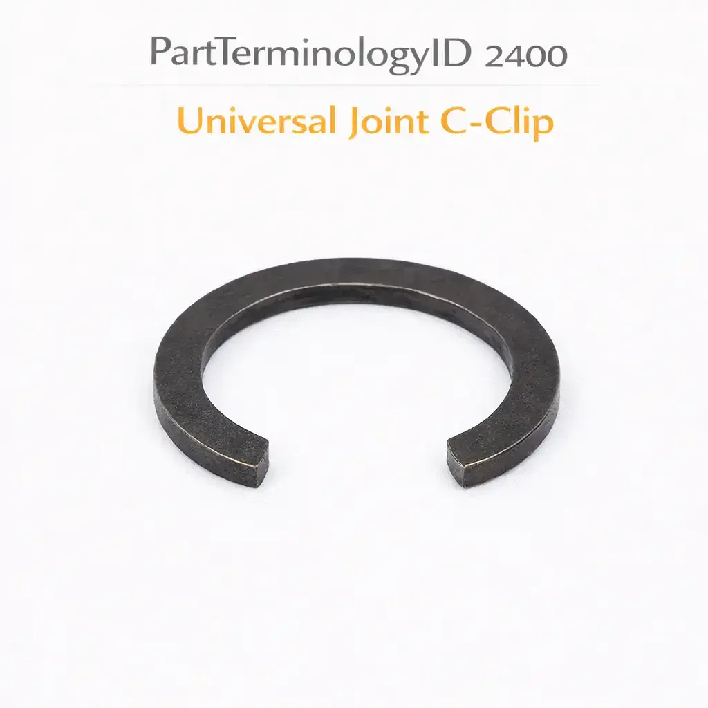
Universal Joint C-Clip (PartTerminologyID 2400): Where Series Designation, Clip Dimensions, and Material Specification Determine Whether the Bearing Cup Stays in the Yoke
Written by Arthur Simitian | PartsAdvisory
PartTerminologyID 2400, Universal Joint C-Clip, is the retaining clip that secures the bearing cup of a universal joint within the yoke ear bore after the cup has been pressed to its correct installation depth. That definition locates the clip correctly at the bearing cup retention point. It does not specify the U-joint series designation the clip is designed for, the clip inner diameter, the clip wire diameter, the clip material, the clip thickness at the retention groove contact surface, whether the clip is an inside snap ring that seats in a groove in the yoke ear bore or an outside snap ring that seats in a groove on the bearing cup outer surface, what the groove width specification is that the clip must fit without rocking or binding, what the retention force specification is, whether the clip is pre-formed to its installed geometry or requires spreading before installation, what the correct installation tool is, or whether the clip is sold individually or in a set of four covering all four bearing cup positions on one U-joint assembly. A listing under PartTerminologyID 2400 that specifies a U-joint series without the clip inner diameter, the wire diameter, and whether the clip is inside or outside retention cannot be evaluated by a technician who has a set of U-joint clips in hand and is verifying the replacement specification before pressing the bearing cups.
For sellers, PartTerminologyID 2400 is a hardware listing that is almost never the primary purchase. The Universal Joint C-Clip is sourced when a new U-joint is being installed and the clips that came with the U-joint are the wrong size for the yoke, or when a U-joint is being reused after inspection and the original clips are distorted or corroded beyond reuse, or when a yoke is being reused with new U-joints and the original clips were lost or damaged during disassembly. In all three cases, the buyer has a specific yoke and a specific U-joint already in hand, which means they know the series designation, the yoke ear bore diameter, and the snap ring groove dimensions before they search. The listing must confirm the clip specification matches those known dimensions.
The consequence of an incorrect C-clip on a U-joint installation is not a dimensional mismatch discovered before installation: it is a retention failure discovered under load. A clip that is too thin in wire diameter will seat in the groove but will not provide the lateral retention force required to prevent the bearing cup from walking out of the yoke ear bore under the cyclic axial loads imposed by driveshaft articulation. A clip that is too thick will not seat in the groove at all and the technician will know immediately. A clip that is the correct wire diameter but the wrong inner diameter will either not reach the groove bottom or will be over-compressed in the groove, both of which compromise retention. All three dimensional errors produce either an installation failure or a delayed retention failure, and the delayed retention failure is the more dangerous outcome because it occurs at speed on the highway when the bearing cup walks out of the yoke and the propshaft separates from the drivetrain.
For sellers, the listing under this PartTerminologyID is only useful if it specifies the U-joint series designation, the clip type, the clip inner diameter, the wire diameter, the groove width compatibility, the material, and whether the clip is sold individually or in a set. Without those six attributes, the listing cannot prevent the retention failure that a dimensionally incorrect clip produces.
What the Universal Joint C-Clip Does
Retaining the bearing cup after it is pressed to installation depth
When a U-joint bearing cup is pressed into a yoke ear bore, it is driven to a specific depth at which the clip groove in the bore aligns with the clip groove on the cup or at which the cup face is flush with the bore opening for outside clip designs. At this depth, the C-clip is installed to lock the cup in position and prevent it from moving axially out of the bore under the loads of driveshaft operation.
The C-clip works by spanning the groove opening and bearing against both groove walls simultaneously. The clip's spring tension holds it in the groove and the groove walls provide the mechanical stop that prevents axial cup movement. The retention force is the product of the clip material's spring tension, the groove depth, and the bearing contact area between the clip face and the groove walls.
During driveshaft operation, the bearing cup experiences axial loads from the U-joint articulation angle. Every revolution of the driveshaft at an operating angle produces one load cycle on each clip, alternating between a push force that drives the cup deeper into the bore and a pull force that pulls the cup toward the bore opening. The pull cycle is the critical load direction for clip retention: the clip must resist the pull force over the full service life of the U-joint without fatigue or relaxation.
Inside versus outside clip retention
An inside clip seats in a groove machined inside the yoke ear bore, typically near the bore opening. The cup is pressed into the bore until it clears the groove, then the clip is snapped into the groove to retain the cup. The inside clip contacts the cup face or a shoulder on the cup outer surface when the cup tries to move outward. This is the most common retention arrangement on domestic passenger vehicle and light truck propshafts.
An outside clip seats in a groove machined on the outer surface of the bearing cup, near the cup mouth. The cup is pressed into the bore until the groove on the cup aligns with the bore opening or with a matching groove in the bore wall. The outside clip is then installed in the cup groove rather than the bore groove. Outside clips are common on some foreign vehicle propshafts and on some aftermarket yoke designs. They are also used on some OE applications where the yoke bore does not have sufficient wall thickness for a machined groove.
The inside and outside clip types have the same function but different installation geometry and different dimensional specifications. An inside clip specified by the yoke bore groove dimensions and an outside clip specified by the bearing cup groove dimensions will have different inner diameters even for the same U-joint series because the groove locations are at different diameters on the bore wall versus the cup outer surface.
The clip as a safety-critical retention component
The U-joint C-clip is not a component where a close approximation is adequate. A propshaft that loses a bearing cup at highway speed because an undersized clip walked out of its groove during the pull cycle of driveshaft articulation becomes an uncontrolled projectile capable of penetrating the vehicle floor, contacting the road surface and vaulting the vehicle, or striking other vehicles. Propshaft separation events from U-joint retention failures are among the most consequential drivetrain failures in terms of vehicle control loss and secondary collision risk.
The safety-critical nature of this component means the listing cannot rely on the buyer's judgment about whether a close-dimension clip is adequate. The clip specification must be exact, the tolerance must be stated, and the listing must note that clips outside the specified dimension range are not acceptable substitutes regardless of how close they appear.
Clip material and fatigue resistance
U-joint C-clips are typically manufactured from spring steel, which provides the elastic properties required for snap-in installation and the fatigue resistance required for the cyclic load environment of the driveshaft operating angle. The spring steel must be hardened to a specific Rockwell hardness range to maintain its spring tension and groove contact force over the full U-joint service life.
A clip that is too soft will take a set over time: it will compress slightly in the groove and the effective retention force will decrease below the designed value before the U-joint reaches its expected service interval. A clip that is too hard will be brittle and may fracture at the snap-in installation step when it is spread to clear the bore wall before seating in the groove. The correct hardness range is stated in the U-joint manufacturer's specification for the series and the clip position.
Stainless steel clips are available for some applications where corrosion resistance is a priority, such as marine propshaft applications or vehicles operated in severe road salt environments. Stainless steel has lower spring tension than hardened carbon spring steel at the same wire diameter, which means a stainless clip must have a larger wire diameter than a carbon steel clip to achieve the same retention force. A stainless clip specified by its wire diameter for a carbon steel groove may not achieve adequate retention force even if it seats correctly in the groove.
The Specifications That Determine Correct Clip Fitment
U-joint series designation
The U-joint series designation narrows the clip specification to the known groove dimensions for that series. As established in the Universal Joint post (PartTerminologyID 2392), the series designation encodes the cross dimensions and bearing cup outer diameter. The clip groove in the yoke bore or on the cup outer surface is dimensioned to match the bearing cup for that series. The series designation is the first fitment attribute.
Clip type: inside or outside
Inside clips seat in the yoke bore groove. Outside clips seat in the cup outer surface groove. The clip type determines which groove dimensions apply.
Clip inner diameter
The inner diameter of the clip in its installed, compressed state. For inside clips, this is the diameter of the circle described by the clip inside edge when seated in the groove. For outside clips, this is the diameter at the cup groove bottom. State in millimeters to two decimal places.
Wire diameter
The wire diameter in millimeters to two decimal places. The wire diameter determines the groove width required to seat the clip without binding and the clip's spring tension and retention force.
Groove width compatibility
State the groove width range the clip is designed for, in millimeters. A groove that is wider than the clip wire diameter allows the clip to rock in the groove rather than seating stably against both groove walls. A groove that is narrower than the clip wire diameter will not accept the clip.
Material and hardness
Spring steel with hardness range stated in Rockwell scale. Note if stainless steel is available and state the wire diameter increase required for equivalent retention force.
Quantity
State whether the listing covers one clip or a set of four. A single U-joint assembly uses four clips, one per bearing cup. Selling four clips as a set matches the quantity to the installation requirement and prevents the buyer from discovering mid-installation that they purchased only one clip.
Why This Part Generates Returns
Buyers order the wrong U-joint C-clip because:
the U-joint series is specified but the inside versus outside clip type is not, and the buyer receives inside clips for an outside clip yoke application
the wire diameter is not stated and the replacement clips are too thick to seat in the groove or too thin to provide adequate retention force
the inner diameter is not stated and the clips are too large to contact the groove bottom or too small to spread over the bore wall during installation
the listing covers one clip and the buyer needed four, discovering the shortage mid-installation
the clip material is not stated and a soft clip takes a permanent set in the groove within one service interval, reducing the retention force below the design value
the installation tool requirement is not noted and the clips are damaged during installation with an improvised tool that deforms the wire at the installation contact point
Status in New Databases
PIES/PCdb: PartTerminologyID 2400, Universal Joint C-Clip
PIES 8.0 / PCdb 2.0: No change
Top Return Scenarios
Scenario 1: "Inside clips sent for outside clip yoke, clips do not reach the cup groove on the outer surface"
The listing specified a U-joint C-clip by series designation without stating the clip type. The yoke uses outside clip retention where the clip seats in a groove on the outer surface of the bearing cup. The inside clips that arrived have a larger inner diameter matched to the yoke bore groove, not the cup outer surface groove. When the technician attempts to install the inside clips in the cup outer surface groove, the clips are too large to seat in the smaller-diameter cup groove and rattle on the cup surface without providing any retention.
Prevention language: "Clip type: [inside snap ring, seats in yoke bore groove / outside snap ring, seats in bearing cup outer surface groove]. Verify your yoke's clip retention type before ordering. Inside clips and outside clips for the same U-joint series have different inner diameters because the bore groove and the cup outer surface groove are at different diameters. They are not interchangeable."
Scenario 2: "Wire diameter too thin, clip seated in groove but walked out under driveshaft articulation load at highway speed"
The replacement clips have the correct inner diameter but a wire diameter that is 0.2mm smaller than the original specification. The thinner wire seated in the groove without difficulty and appeared correctly installed. Under the cyclic pull load of driveshaft articulation at highway speed, the thinner wire provided insufficient lateral retention force against the groove wall. The clip walked progressively out of the groove over 3,000 miles. The bearing cup then moved axially out of the bore. The propshaft contacted the tunnel floor at highway speed before the driver noticed the vibration and stopped the vehicle.
Prevention language: "Wire diameter: [X.XX]mm. Tolerance: [+0.00 / -0.00]mm. Do not substitute a clip with a smaller wire diameter than specified. A thinner wire provides less bearing contact area against the groove wall and less retention force under the cyclic axial loads of driveshaft articulation. A clip that appears correctly installed but has an undersized wire diameter can walk out of the groove progressively under highway operating loads. Use only clips within the specified wire diameter tolerance."
Scenario 3: "Set of one clip purchased, installation stopped mid-process with three cups unsecured"
The listing did not state the quantity and the product image showed a single clip. The buyer purchased one unit assuming it was a set of four. After pressing all four bearing cups into the yoke bores and installing the first clip, the buyer discovered only one clip in the packaging. The propshaft was left with three unsecured bearing cups while the buyer sourced additional clips. During this interval, two of the unsecured cups moved slightly in their bores from handling and required repositioning before the remaining clips could be installed.
Prevention language: "Quantity: [1 clip / set of 4 clips]. A single U-joint assembly uses four clips, one per bearing cup position. Verify the quantity in this listing before purchasing. A U-joint installation that is stopped mid-process with unsecured bearing cups risks cup movement in the bores that may require repositioning before the remaining clips can be correctly installed."
Scenario 4: "Clip inner diameter too large, clip does not contact groove bottom, retention force zero"
The replacement clips have an inner diameter 1.5mm larger than the groove diameter in the yoke bore. When the technician installs the clips, they drop into the groove opening but float on the groove walls rather than bearing against the groove bottom. The clip provides no spring tension against the groove bottom and no retention force against the bearing cup face. The first engagement from drive to reverse causes an audible clunk from the bearing cup moving axially within the yoke bore. On inspection, all four clips are found to have the same loose fit in their respective grooves.
Prevention language: "Clip inner diameter: [X.XX]mm. Groove diameter in yoke bore: [X.XX]mm. The clip inner diameter must be smaller than the groove bottom diameter so the clip bears against the groove bottom with spring tension when installed. A clip with an inner diameter larger than the groove diameter cannot contact the groove bottom and provides no retention force. Measure the groove bottom diameter before ordering if the original clip specification is unknown."
Scenario 5: "Correct dimensions, improvised installation tool, clip wire kinked at installation contact point, retention force compromised"
The correct clips were ordered and received. The technician did not have a snap ring pliers sized for the clip inner diameter and used a pair of standard pliers with smooth jaws to spread and install the clips. The smooth jaws contacted the clip wire at two small points rather than distributing the spreading load along the clip arc, kinking the wire at both contact points. The kinked clips seated in the groove but the kink reduced the spring tension in the kinked sections. The retention force was non-uniform around the groove circumference and two of the four cups worked loose within 8,000 miles.
Prevention language: "Installation tool required: internal snap ring pliers sized for [X.XX]mm inner diameter clips. Do not install U-joint clips with standard pliers or improvised tools. A tool that contacts the clip wire at two small points rather than distributing the load along the clip arc will kink the wire and reduce the spring tension at the kink points. A kinked clip has a non-uniform retention force distribution and may allow the bearing cup to move under cyclic load at the kink location."
What to Include in the Listing
Core essentials
PartTerminologyID: 2400
component: Universal Joint C-Clip
U-joint series designation the clip is designed for (mandatory)
clip type: inside snap ring or outside snap ring (mandatory)
clip inner diameter in mm to two decimal places (mandatory)
wire diameter in mm to two decimal places with tolerance (mandatory)
groove width compatibility range in mm (mandatory)
material: spring steel with hardness range in Rockwell, or stainless steel (mandatory)
retention force specification in the axial direction at the groove engagement depth (mandatory for safety-critical disclosure)
quantity: 1 or set of 4 (mandatory)
installation tool specification: internal snap ring pliers inner diameter range (mandatory)
safety note on dimensional substitution: not acceptable (mandatory)
Fitment essentials
U-joint series designation (primary fitment attribute)
inside or outside clip type
yoke type: propshaft yoke, transfer case output yoke, differential companion flange, or other
vehicle application if known: confirms which combination of series and retention type applies
Dimensional essentials
clip inner diameter in mm to two decimal places
wire diameter in mm to two decimal places with tolerance
clip outer diameter in mm (relaxed, uninstalled state)
groove width compatibility in mm
groove depth minimum and maximum in mm
clip installed gap width in mm (the opening in the C shape that allows installation over the bore wall)
Image essentials
single clip in isolation with inner diameter and wire diameter callouts
set of four clips shown together for set listings
clip seated correctly in inside groove shown in cross-section with bearing cup face against clip
clip seated correctly in outside cup groove shown in cross-section
internal snap ring pliers shown engaging the clip for installation
kinked clip shown alongside correctly installed clip to illustrate installation tool consequence
groove cross-section showing wire diameter versus groove width relationship
Catalog Checklist for ACES/PIES Teams
PartTerminologyID = 2400
require U-joint series designation (mandatory)
require clip type: inside or outside (mandatory)
require clip inner diameter in mm to two decimal places (mandatory)
require wire diameter in mm with tolerance (mandatory)
require groove width compatibility range (mandatory)
require material with hardness specification (mandatory)
require quantity: 1 or set of 4 (mandatory)
require installation tool specification (mandatory)
require safety note on dimensional substitution (mandatory)
differentiate from universal joint (PartTerminologyID 2392): the U-joint is the complete cross-and-bearing assembly; the C-clip is the retention hardware that secures the bearing cups of that assembly in the yoke; both are associated with the same installation event but are separate PartTerminologyIDs; confirm clip inclusion status in the U-joint listing and cross-reference 2400 if clips are not included
differentiate from U-joint strap kit and U-bolt kit: strap and U-bolt retention hardware cover non-clip retention methods; 2400 covers snap ring and C-clip retention only; verify the retention method before selecting the correct hardware PartTerminologyID
flag inside versus outside clip type as mandatory: the two types have different inner diameters for the same U-joint series and are not interchangeable; this is the most common single-attribute error for this PartTerminologyID
flag wire diameter tolerance as mandatory: a wire diameter that is within visual inspection tolerance of the specification may be outside the functional retention force tolerance; the tolerance must be stated to prevent substitution with a visually similar clip of different wire gauge
flag quantity as mandatory: a single-clip listing for a four-clip installation requirement is the most common purchasing error for this PartTerminologyID; it is fully preventable by stating the quantity prominently
flag safety note as mandatory: the C-clip is a safety-critical retention component for a propshaft that rotates at high speed under the vehicle; the listing must note that dimensional substitutions are not acceptable and must state the consequence of a retention failure explicitly
FAQ (Buyer Language)
How do I measure the groove in my yoke to confirm the clip specification?
Remove the bearing cup from one yoke ear bore. Use a caliper to measure the bore inner diameter at the groove bottom for inside clips, or measure the cup outer surface at the groove bottom for outside clips. That measurement is the clip inner diameter specification. Then measure the groove width with a feeler gauge or a set of gauge pins: the groove width must match the wire diameter of the replacement clip within the specified tolerance. If the original clip is available and undamaged, measuring the original clip's inner diameter and wire diameter directly is the most reliable confirmation of the correct replacement specification.
My U-joint came with clips but they do not fit my yoke. What went wrong?
Two scenarios produce this situation. The first is a U-joint sold for a different retention type than your yoke: if your yoke uses outside clips and the U-joint came with inside clips, the clips will not seat in the cup groove regardless of their dimensions. The second is a U-joint from a different series than your yoke: even if both are inside clip designs, a 1310 series clip will not fit a 1350 series groove because the groove diameter is different. Identify your yoke series and retention type before ordering replacement clips.
Can I reuse the original clips if they look undamaged?
If the original clips show no corrosion pitting, no visible kinks or flat spots on the wire, and spring back to their original shape after being removed from the groove, they can be reused. Clips that show any deformation at the installation contact points from the original installation tool, any corrosion that has pitted the wire surface, or any permanent set that prevents them from returning to their design inner diameter after removal should be replaced. Given the safety-critical function of the clip and the low cost of a replacement set, replacing the clips at every U-joint service event is the safer practice regardless of visible condition.
What grease do I apply to the clip groove before installation?
No grease is applied to the clip groove. The clip must seat in a clean, dry groove to achieve its designed contact force against the groove walls. Grease in the groove reduces the friction between the clip wire and the groove walls that contributes to the clip's resistance to walking out of the groove under cyclic load. Wipe the bore groove clean with a lint-free cloth before installing the clip.
Cross-Sell Logic
Universal Joint (PartTerminologyID 2392: the C-clip is installed as part of a U-joint replacement; cross-reference the correct U-joint series alongside every C-clip listing)
Internal Snap Ring Pliers (the installation tool for C-clips; the clip listing should note the correct pliers inner diameter range)
U-Joint Strap Kit or U-Bolt Kit (for yokes that use strap or U-bolt retention rather than clip retention; the retention hardware PartTerminologyID cross-reference confirms which retention type the buyer's yoke uses)
Drive Shaft Assembly (PartTerminologyID 2308: if the propshaft yoke ears are worn or the bore surface is corroded beyond the clip groove, the yoke or the complete propshaft assembly requires replacement)
Frame as "the C-clip retains the bearing cup in the yoke bore. The bearing cup contains the needle rollers that carry the torque load. The U-joint cross is what the bearing cup rotates around. The yoke is what the bearing cup is pressed into. The clip is the last component installed and the one that determines whether everything else stays together at speed."
Final Take for PartTerminologyID 2400
Universal Joint C-Clip (PartTerminologyID 2400) is the smallest component in the drivetrain series by physical dimension and one of the most consequential by failure outcome. A C-clip that is dimensionally correct and correctly installed is invisible in operation: it performs its retention function without any feedback to the driver or the technician for the full service life of the U-joint. A C-clip that is dimensionally incorrect or incorrectly installed produces no immediate symptom at low speed, produces a progressive clunk as the cup begins to move in the bore at moderate speed, and produces a propshaft separation event at highway speed that has consequences far beyond the drivetrain.
The inside versus outside clip type distinction resolves which groove the clip seats in and therefore which diameter specification applies. The wire diameter with tolerance resolves the retention force question that inner diameter alone cannot answer. The quantity statement resolves the mid-installation shortage that is the most common purchasing error for this PartTerminologyID. The safety note on dimensional substitution resolves the impulse to use a visually similar clip from a hardware assortment when the correct specification is not immediately available.
State the series designation. State the clip type. State the inner diameter and wire diameter with tolerance. State the groove width compatibility. State the material and hardness. State the quantity. State the installation tool. State that dimensional substitutions are not acceptable and explain why. That is the same listing strategy as every other PartTerminologyID in this series: specific attributes at every level to become a listing buyers can act on without guessing. For PartTerminologyID 2400, the wire diameter tolerance is the attribute that separates a clip that retains the bearing cup for the full U-joint service life from one that walks out of the groove on the highway, and no listing that omits it has communicated the specification adequately.