Universal Joint (PartTerminologyID 2392): Where Series Designation, Cross Dimensions, and Bearing Cup Retention Determine Whether the Driveshaft Survives Highway Speed
Written by Arthur Simitian | PartsAdvisory
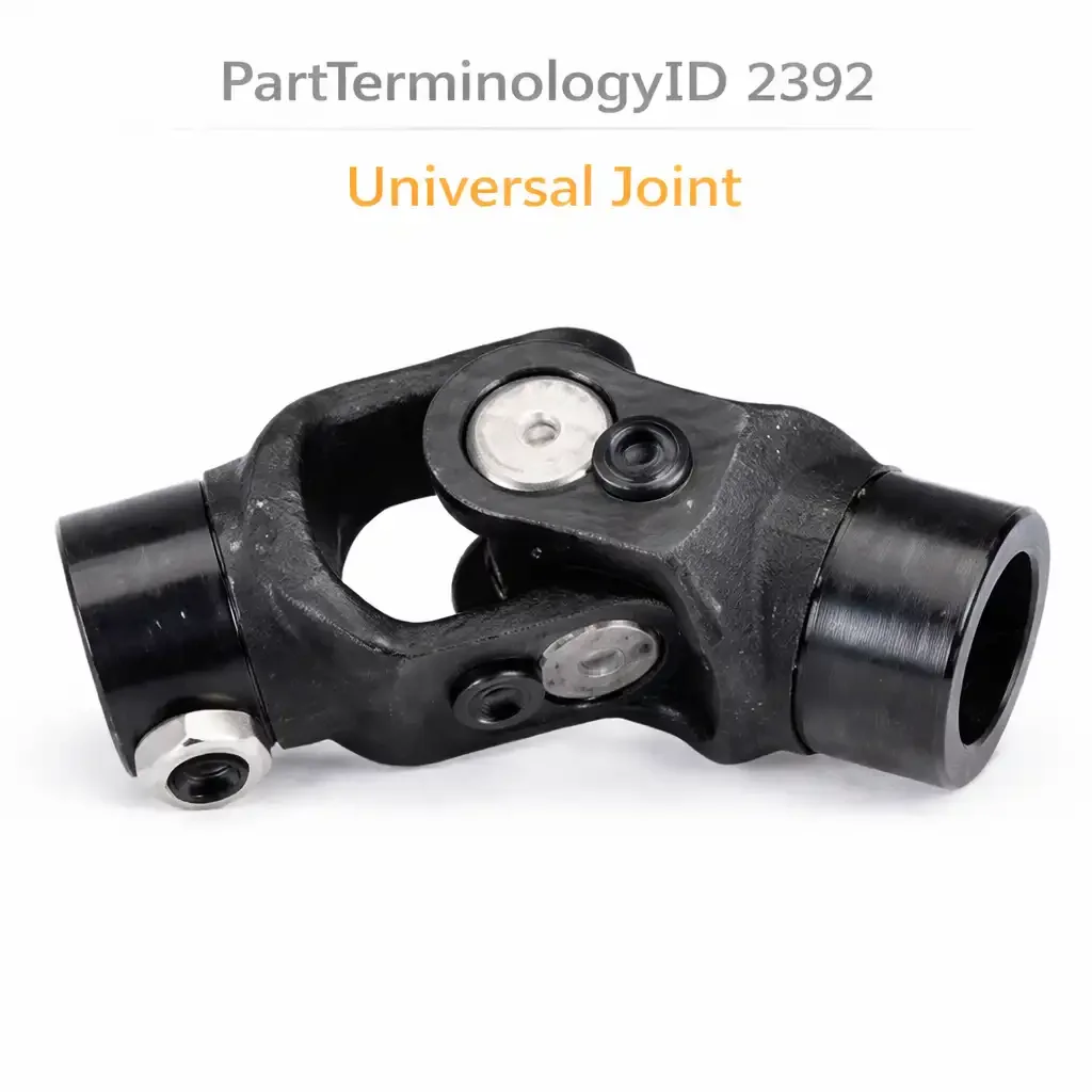
PartTerminologyID 2392, Universal Joint, is the cross-and-bearing assembly that allows a driveshaft to transmit torque through an angle between two shafts whose centerlines are not aligned. That definition covers the function in one sentence. It does not specify the U-joint series designation, the cross outer diameter, the bearing cup outer diameter, the bearing cup length, the snap ring groove configuration, the bearing cup retention method, whether the U-joint uses inside snap rings, outside snap rings, U-bolts, straps, or a combination retention system, the bearing cup material specification, the needle roller count and diameter, the grease fitting location and thread specification, whether the U-joint is a solid cross or a full-round cross, whether it is pre-greased or requires field lubrication before installation, what the working angle rating is, what the torque capacity is, whether the U-joint is a conversion joint that adapts between two different series yokes, or whether the bearing cups include the grease seal and how the seal is retained in the cup mouth. A listing under PartTerminologyID 2392 that provides vehicle year, make, and model without the series designation, the cross dimensions, and the bearing cup retention method cannot be evaluated by any technician who has the worn U-joint in hand and is matching the replacement before beginning disassembly.
For sellers, PartTerminologyID 2392 is one of the highest-volume individual driveline component listings in the drivetrain category because it applies to every rear-wheel-drive vehicle, every four-wheel-drive vehicle, and every front-wheel-drive vehicle that uses a propshaft for any portion of its torque delivery. Universal joints are wear components that have a defined service life determined by their working angle, their operating speed, their grease condition, and their torque exposure. A U-joint that has been in service for 80,000 to 150,000 miles at highway speeds and towing loads will typically show needle roller fatigue at the cross trunnion surface, bearing cup brace wear, or grease seal failure that allows contamination into the bearing cavity. The replacement buyer population is correspondingly broad: it includes professional driveshaft shops rebuilding propshafts, four-wheel-drive technicians replacing worn U-joints at transfer case yokes and differential flanges, fleet maintenance technicians replacing U-joints on a scheduled basis across a large commercial vehicle population, and do-it-yourself buyers replacing a clunking U-joint on a personal vehicle before a long trip.
The breadth of that buyer population and the volume of this listing make the series designation the attribute that most consistently prevents incorrect orders. The U-joint series system, which assigns a series number to each combination of cross outer diameter and bearing cup outer diameter within the most widely used standard, organizes the catalog space for this PartTerminologyID more efficiently than dimensional lookup for the majority of applications. A buyer who knows they need a 1310 series U-joint for a GM truck application and a seller who states 1310 in the listing have resolved the core fitment question before a single dimension is checked. A buyer who does not know the series number and a seller who does not state it must rely entirely on dimensional cross-reference, which is accurate but slower and more error-prone for the general buyer population.
For sellers, the listing under this PartTerminologyID is only useful if it specifies the series designation, the cross outer diameter, the bearing cup outer diameter, the bearing cup length, the bearing cup retention method, the grease fitting specification, and the working angle rating. Without those seven attributes, the listing cannot be evaluated by either the experienced driveshaft shop technician or the first-time U-joint replacement buyer.
What the Universal Joint Does
Transmitting torque through an operating angle
A conventional Cardan universal joint consists of a cross-shaped center piece, the spider, with four trunnions extending from it at 90-degree intervals in two perpendicular planes. Each pair of opposing trunnions fits into a bearing cup that is retained in a yoke ear. The two bearing cups in one plane engage one yoke, and the two bearing cups in the perpendicular plane engage the other yoke. When the two yokes are at an angle to each other, the cross pivots on all four bearing cups simultaneously to allow the angle while transmitting the rotary motion from the driving shaft to the driven shaft.
The torque is transmitted through the needle rollers between the trunnion surface and the bearing cup inner wall. The needle rollers roll along the trunnion as the joint articulates through its working angle. The quality of the needle roller surface, the trunnion surface, and the lubrication maintained between them determines the service life of the U-joint.
The velocity variation inherent in a single Cardan joint
A single Cardan universal joint does not transmit uniform velocity through an angle. When the two shafts are at an angle to each other, the driven shaft accelerates and decelerates twice per revolution relative to the driving shaft. The magnitude of this velocity variation increases with the operating angle. At small angles of two to three degrees, the variation is minor and produces no perceptible vibration. At angles above eight to ten degrees, the velocity variation is large enough to produce a second-order vibration that is felt in the driveshaft and transmitted to the vehicle body.
On a two-joint propshaft, this velocity variation is cancelled by phasing the two U-joints so that the second joint's deceleration phase coincides with the first joint's acceleration phase. This cancellation requires that both U-joints operate at equal angles and that their yokes are in the correct phase relationship, typically with both yoke ears in the same plane. When a U-joint is replaced and the propshaft is reinstalled at the wrong phase angle, the velocity variation from the two joints adds rather than cancels, producing a vibration that is directly attributable to the incorrect phasing of the replacement installation.
The listing must note the phase angle requirement for propshaft reinstallation: align the yoke ears in the same plane before tightening the retention hardware.
The grease seal and its role in U-joint service life
The grease seal at the mouth of each bearing cup retains the grease pack inside the cup and prevents road contamination from entering the needle roller bearing cavity. Most U-joint grease seals are a lip seal retained by a groove or a press fit in the cup mouth. When the grease seal fails, water, mud, and abrasive grit enter the bearing cavity and contaminate the grease, producing accelerated needle roller wear at the trunnion contact zone. A U-joint failure that is preceded by a grease seal failure typically develops from the outside in: the rust and pitting that appears on the trunnion surface near the cross center after a seal failure is evidence of contamination-driven wear rather than fatigue wear.
The grease fitting on a serviceable U-joint allows periodic regrease of the bearing cavities that extends the U-joint service life. A properly regrease cycle purges the old grease and any contamination that has entered past a marginal seal and replaces it with fresh grease, restoring the bearing film and extending the service life. U-joints without a grease fitting, which are common on many factory-installed propshafts, are intended to be replaced rather than regreased and have a defined service life that is shorter than a serviceable U-joint on an equivalent application.
The working angle and the torque capacity
The working angle is the angle between the centerlines of the two shafts connected by the U-joint. The U-joint's torque capacity decreases as the working angle increases because the needle rollers at the trunnion tips must travel a greater arc per revolution at higher angles, increasing the contact stress at the roller ends. The rated torque capacity stated in the U-joint specification assumes a specific working angle, typically three degrees for most catalog ratings. A U-joint operating at a higher angle than the rating basis carries proportionally less torque before fatigue failure, and a U-joint subjected to torque loads that exceed its rating at its operating angle will fail before its expected service interval.
On lifted four-wheel-drive vehicles where the suspension lift has increased the driveshaft operating angles beyond the factory design range, U-joint replacement intervals should be shortened or heavy-duty U-joints with higher torque ratings should be specified. The listing should note the working angle rating explicitly and should include a note for lifted vehicle applications.
The U-Joint Series System
How the series designation works
The U-joint series system assigns a number to each combination of cross outer diameter and bearing cup outer diameter. The most widely used series in North American passenger vehicles and light trucks are the 1310, 1330, 1350, 1410, and 1480 series, which cover the range from compact car propshafts to heavy-duty truck propshafts.
The series number encodes the approximate cross outer diameter and bearing cup outer diameter for each series. Within each series, all U-joints have the same cross outer diameter and bearing cup outer diameter and are mechanically interchangeable in terms of yoke fit. Differences within a series exist in the bearing cup length, the grease fitting style, the bearing cup retention method, and the seal design, but the fundamental yoke fit is consistent across all U-joints in the same series.
The series system allows a buyer who knows their series designation to narrow the catalog to a small subset of relevant listings without measuring the cross or bearing cup dimensions. It is the most efficient single attribute for this PartTerminologyID from the buyer's perspective and should be the first attribute in every listing under PartTerminologyID 2392.
Common series and their primary applications
The 1310 series is the most common series in North American passenger vehicles and light trucks. It uses a cross outer diameter of approximately 1.062 inches (27.0mm) and a bearing cup outer diameter of 1.062 inches (27.0mm). It is found on GM, Ford, and Chrysler passenger cars and light trucks from the 1960s through the present on applications with moderate torque requirements.
The 1330 series uses the same bearing cup outer diameter as the 1310 but a slightly longer bearing cup. It is common on larger GM trucks and some Ford applications where the additional cup length provides greater working angle capacity.
The 1350 series uses a larger cross outer diameter than the 1310 and 1330. It is found on three-quarter-ton and one-ton trucks from all domestic manufacturers where the higher torque capacity of the larger series is required.
The 1410 series uses an even larger cross and is found on heavy one-ton trucks, commercial vehicles, and high-torque applications including some aftermarket performance driveshafts on high-horsepower vehicles.
The 1480 series is used on heavy-duty commercial vehicles and is the largest commonly cataloged series in the domestic light commercial vehicle market.
The conversion U-joint
A conversion U-joint, also called a mismatched U-joint, connects two yokes of different series. The most common conversion U-joint in the domestic market connects a 1310-series flange yoke to a 1330-series tube yoke, or a 1350-series differential flange to a 1310-series propshaft tube. Conversion U-joints have two pairs of bearing cups of different outer diameters, one pair for each yoke in the connection.
A listing that specifies a conversion U-joint must state both series designations in the listing, both bearing cup outer diameters, and which end of the cross corresponds to which series. A buyer who receives a standard 1310 U-joint when they needed a 1310-to-1350 conversion joint discovers the mismatch at the differential flange when one pair of cups is too small for the flange yoke ears.
The bearing cup retention systems
The bearing cup retention method is the second most critical specification after the series designation because it determines whether the replacement U-joint is compatible with the existing yoke without modification.
Inside snap rings sit in grooves machined inside the yoke bore and retain the bearing cup from inside the yoke ear. This is the most common retention method on domestic passenger vehicle propshafts and yoke assemblies. The snap ring is removed before pressing the old cup out and the new cup in, and a new snap ring is installed in the groove after the new cup is seated.
Outside snap rings sit in grooves machined on the outside of the bearing cup rather than inside the yoke bore. Outside snap rings are common on some foreign vehicle applications and on some aftermarket yoke designs. A yoke designed for inside snap rings cannot use a U-joint with outside snap rings without machining new grooves, and vice versa.
U-bolts and round straps clamp the bearing cup into the yoke without a snap ring groove. U-bolt retention is common on some truck driveshafts and on transfer case yokes. Strap retention is common on some propshaft-to-differential flange connections. A U-joint designed for snap ring retention cannot be installed in a U-bolt or strap yoke without modification.
Some OE propshafts use a spicer-style wing bearing retention where the bearing cup flange catches on the yoke face rather than being retained by a snap ring. This design requires a U-joint with the matching flange geometry on the bearing cup.
The listing must state the retention method and must note whether the snap rings are included with the U-joint.
The Grease Fitting Specification
Location and thread specification
The grease fitting on a serviceable U-joint is located on the cross center body between the four trunnions. The fitting thread is typically a standard taper pipe thread (NPT) or a straight thread with a specific diameter and pitch. On some U-joints, the grease fitting is located on the side of the cross rather than the center, and the grease channel within the cross routes grease from the fitting to all four trunnion cavities.
The grease fitting thread specification must match the grease gun fitting the technician is using. A 1/4-28 straight thread fitting requires a different grease gun adapter than a 1/8 NPT fitting. A U-joint ordered without confirming the grease fitting thread specification may arrive with a fitting that does not accept the standard grease gun adapter, preventing the pre-installation lubrication and the first service lubrication.
Pre-greased versus field-lubrication required
Some replacement U-joints are shipped pre-greased from the factory with the grease pack already installed in the bearing cavities. Others are shipped dry and require field lubrication before installation. A dry U-joint installed without initial lubrication will fail at the first needle roller contact under load because the bearing surfaces will run metal-to-metal until the first grease service introduces lubrication.
The listing must state whether the U-joint is pre-greased or requires field lubrication, and must provide the grease specification for the initial lubrication and for subsequent service intervals.
The Needle Roller Specification
Needle roller count and diameter
The needle rollers in each bearing cup carry the load between the trunnion surface and the cup inner wall. The roller count and diameter determine the load distribution across the bearing contact area. A cup with more rollers of smaller diameter distributes the load more evenly and has a higher fatigue life at a given load, but is more expensive to manufacture. A cup with fewer rollers of larger diameter has a higher load per roller and a shorter fatigue life at the same load but is less expensive.
Performance and heavy-duty U-joint replacements often use a higher roller count than the OE specification, which is reflected in a higher torque rating at the same working angle. A listing for a heavy-duty U-joint must state the roller count and compare it to the OE specification to explain the torque rating improvement.
Full-round cross versus solid cross
A standard cross is a single-piece casting or forging with four integral trunnions. A full-round cross, also called a combination cross or a conversion cross, is machined to allow different bearing cup outer diameters at opposite ends of each trunnion pair. Full-round cross designs are used in conversion U-joints and in some performance applications where the cross material is upgraded for higher torque capacity.
The cross material specification is relevant for high-torque performance applications: a cross machined from alloy steel with a higher case hardening depth has a higher fatigue strength at the trunnion contact zone than a standard carbon steel cross. The listing should state the cross material specification for U-joints marketed for high-performance or high-torque applications.
Specifications That Determine Correct Fitment
Series designation
The mandatory first attribute. State the series number in the listing title and in the first specification line of the listing body.
Cross outer diameter and bearing cup outer diameter
State in both inches and millimeters. The series designation implies these dimensions for standard series but stating them explicitly allows a buyer who is cross-referencing from a dimensional measurement rather than a known series number to confirm the match.
Bearing cup length
State in millimeters. Within the same series, bearing cup length may vary between applications. A longer cup provides a greater needle roller contact length and higher torque capacity but requires a yoke with sufficient ear depth to accept the longer cup.
Bearing cup retention method
Inside snap ring, outside snap ring, U-bolt, strap, or spicer wing. State the retention method explicitly and note whether snap rings are included.
Grease fitting thread and location
Thread specification and location on the cross. State whether the U-joint is pre-greased or requires field lubrication.
Working angle rating
In degrees. The maximum continuous working angle at rated torque. Note the relationship between working angle and torque capacity for buyers on lifted vehicles.
Torque rating
In foot-pounds or Newton-meters at the rated working angle. For heavy-duty or performance U-joints, compare to the OE torque rating.
Snap ring inclusion
Yes or no. If no, state the snap ring specification for the buyer to source separately.
Why This Part Generates Returns
Buyers order the wrong universal joint because:
the series designation is not specified and the cross outer diameter or bearing cup outer diameter does not match the yoke bores
the bearing cup retention method is not specified and a snap ring U-joint is sent for a U-bolt yoke or vice versa
the conversion U-joint requirement is not identified and a standard same-series U-joint is sent for a mismatched yoke application
the bearing cup length is not stated and a longer cup bottoms out in a shallow yoke ear or a shorter cup does not reach the snap ring groove
the grease fitting thread does not match the buyer's grease gun adapter and the U-joint cannot be lubricated on installation
snap rings are not included and the buyer discovers mid-installation that no snap rings came with the U-joint
the U-joint is shipped dry and the buyer installs it without initial lubrication, producing an immediate needle roller failure under first load
the working angle on a lifted vehicle exceeds the U-joint's rated working angle and the U-joint fails before the expected service interval
Status in New Databases
PIES/PCdb: PartTerminologyID 2392, Universal Joint
PIES 8.0 / PCdb 2.0: No change
Top Return Scenarios
Scenario 1: "Series designation not stated, cross diameter matched visually, bearing cup too short for yoke ear depth"
The buyer measured the cross outer diameter and the bearing cup outer diameter from the original U-joint and found a replacement that matched both measurements. The listing did not state the bearing cup length. The replacement bearing cup is 2mm shorter than the original. The yoke ear bore is machined with the snap ring groove at a depth that corresponds to the original cup length. The shorter replacement cup seats 2mm short of the snap ring groove and the snap ring cannot engage the groove. The cup is retained only by interference with the yoke bore wall rather than by the snap ring, and it works out of the bore under the first load cycle.
Prevention language: "Bearing cup length: [X]mm. Verify the bearing cup length matches your yoke ear bore depth before ordering. A bearing cup that is shorter than the yoke ear bore depth will not reach the snap ring groove and cannot be correctly retained. The snap ring must engage the groove for the U-joint to be safely retained in the yoke."
Scenario 2: "Standard 1310 received, application requires 1310-to-1350 conversion, flange yoke cups too small"
The differential flange yoke on this application is a 1350-series flange. The propshaft tube yoke is 1310 series. The listing specified a 1310 series U-joint by vehicle year, make, and model without noting the conversion requirement. The replacement 1310 U-joint has 1310 bearing cups at both ends. The 1350-series flange yoke ear bores are larger than the 1310 bearing cup outer diameter. The 1310 cups rattle in the 1350 flange yoke bores and the U-bolt clamp cannot retain them against the loose fit.
Prevention language: "U-joint configuration: [standard 1310 / 1310-to-1350 conversion]. Differential flange yoke series: [1350]. Propshaft tube yoke series: [1310]. This application uses a conversion U-joint with 1310 cups at the tube yoke end and 1350 cups at the differential flange end. A standard 1310 U-joint is not correct for this application. Verify both yoke series designations before ordering."
Scenario 3: "U-bolt retention yoke, snap ring U-joint received, cups have no flat for U-bolt clamp"
The transfer case yoke on this application uses U-bolt retention. The U-bolt clamps a flat-bottomed bearing cup into a saddle in the yoke. The replacement U-joint has snap ring style cups with a circular cross-section and a snap ring groove rather than a flat bottom. The U-bolt clamp bears against the rounded cup surface rather than the flat, and the cup rotates within the clamp under the first torque application, destroying the yoke saddle.
Prevention language: "Bearing cup retention method: [U-bolt / inside snap ring / outside snap ring / strap]. This yoke uses U-bolt retention. The U-bolt clamps a flat-bottom bearing cup into the yoke saddle. A snap ring style bearing cup with a circular cross-section is not compatible with U-bolt retention. Verify the retention method of your yoke before ordering."
Scenario 4: "U-joint shipped dry, installed without pre-lubrication, needle rollers failed under first load"
The replacement U-joint was shipped dry without a pre-grease pack. The listing did not state that field lubrication was required before installation. The buyer installed the U-joint without introducing grease to the bearing cavities. Under the first torque load, the needle rollers contacted the trunnion and cup surfaces without a lubricating film. The metal-to-metal contact scored the trunnion surface within the first drive cycle. The U-joint produced a clunk on the first reverse-to-drive transition and was found to be seized at one trunnion on inspection.
Prevention language: "Pre-greased: [yes / no, field lubrication required before installation]. This U-joint requires field lubrication before installation. Pump grease through the grease fitting until fresh grease emerges from all four bearing cup seals before installing the U-joint. Do not install this U-joint dry. A dry U-joint under its first torque load will score the needle roller and trunnion surfaces within the first operating cycle."
Scenario 5: "Incorrect phase angle on reinstallation, second-order driveshaft vibration at highway speed"
The propshaft was removed for U-joint replacement. The front and rear yoke orientation was not marked before removal. The propshaft was reinstalled with the front and rear yoke ears 90 degrees out of phase from the correct orientation. The velocity variation from the two U-joints adds rather than cancels at the incorrect phase relationship. A distinct second-order vibration appeared at highway speed that was not present before the U-joint replacement.
Prevention language: "Phase angle note: before removing the propshaft for U-joint replacement, mark the orientation of the front and rear yokes relative to each other with a paint pen or scribe. The front and rear yoke ears must be in the same plane when the propshaft is reinstalled. An incorrect phase relationship between the two U-joints produces a second-order vibration at highway speed that is directly caused by the incorrect reinstallation."
Scenario 6: "Snap rings not included, buyer discovered mid-installation with differential fluid drained and U-joint pressed in"
The listing did not state whether snap rings were included. The buyer assumed they were included because the previous U-joints always came with snap rings. The replacement U-joint arrived without snap rings. The buyer had already drained the rear differential, removed the propshaft, and pressed the new U-joint into the yoke before discovering that no snap rings were in the packaging. The correct snap ring specification was not stated in the listing and the buyer had to identify and source the snap rings separately before the installation could be completed.
Prevention language: "Snap rings: [included / not included]. Snap ring specification if not included: [X]mm inside diameter, [X]mm wire diameter. Verify snap ring inclusion before beginning installation. If snap rings are not included, source the correct specification before removing the propshaft."
Scenario 7: "Lifted truck, increased driveshaft angle, standard U-joint failed at 15,000 miles"
The truck has a 4-inch suspension lift that increased the rear driveshaft operating angle from the factory 3.5 degrees to approximately 9 degrees. The replacement U-joint is the standard OE-equivalent 1350 series rated for continuous operation at 3 to 4 degrees. At 9 degrees operating angle, the needle rollers travel a significantly greater arc per revolution and the contact stress at the roller tips is substantially higher than at the rated angle. The U-joint showed needle roller fatigue and cross trunnion pitting at 15,000 miles, far short of the 80,000-mile service life expected on the factory suspension geometry.
Prevention language: "Working angle rating: [X] degrees continuous at rated torque. Note for lifted vehicles: a suspension lift that increases the driveshaft operating angle above the factory design range reduces the U-joint torque capacity and service life in proportion to the angle increase. For vehicles with suspension lifts greater than 2 inches, specify a heavy-duty U-joint rated for higher continuous working angles, or install a driveshaft with a double-Cardan constant velocity joint at the transfer case output to reduce the operating angle at the rear U-joint."
Scenario 8: "Grease fitting thread mismatch, could not lubricate at installation, cross-drilled channel blocked by manufacturing burr"
The replacement U-joint has a 1/8-27 NPT grease fitting. The buyer's grease gun has a standard hydraulic-thread fitting that engages a 1/4-28 straight thread. The NPT and straight thread fittings are not compatible. The buyer could not deliver grease to the bearing cavities at installation. Additionally, a manufacturing burr in the cross-drilled grease channel partially blocked the grease passage to one trunnion. The blocked trunnion ran without lubrication and the grease seal at that position failed from the elevated temperature of the dry contact within 5,000 miles.
Prevention language: "Grease fitting thread: [1/4-28 straight / 1/8-27 NPT / other]. Verify the grease fitting thread matches your grease gun before installing. After pressing the U-joint into the yoke and installing the snap rings, pump grease through the fitting and confirm that fresh grease emerges from all four bearing cup seals. A cup that does not purge grease indicates a blocked grease passage in the cross and the U-joint should be replaced before the vehicle is returned to service."
What to Include in the Listing
Core essentials
PartTerminologyID: 2392
component: Universal Joint
series designation: 1310, 1330, 1350, 1410, 1480, or other (mandatory)
conversion designation for mismatched yoke applications: both series at each end (mandatory for conversion joints)
cross outer diameter in both inches and millimeters (mandatory)
bearing cup outer diameter in both inches and millimeters (mandatory)
bearing cup length in millimeters (mandatory)
bearing cup retention method: inside snap ring, outside snap ring, U-bolt, strap, or spicer wing (mandatory)
snap rings included: yes or no (mandatory)
snap ring specification if not included: inner diameter and wire diameter in mm (mandatory if not included)
grease fitting thread: 1/4-28 straight, 1/8-27 NPT, or other (mandatory)
grease fitting location: cross center or cross side (mandatory)
pre-greased: yes or no, with field lubrication instruction if no (mandatory)
grease specification: NLGI grade and type for initial and service lubrication (mandatory)
working angle rating in degrees (mandatory)
torque rating in foot-pounds at rated working angle (mandatory)
cross material: carbon steel or alloy steel (mandatory for performance listings)
needle roller count per cup (mandatory for heavy-duty and performance listings)
seal type at bearing cup mouth: lip seal or labyrinth (mandatory)
phase angle reinstallation note (mandatory)
quantity: 1 U-joint assembly (4 bearing cups, 1 cross, snap rings if included)
Fitment essentials
year/make/model/submodel
driveshaft position: front propshaft, rear propshaft, front propshaft at transfer case end, rear propshaft at differential end, or other
series designation at each yoke for conversion joint applications
suspension lift note for four-wheel-drive applications where lift affects working angle
transmission type when series designation varies by transmission option
Dimensional essentials
cross outer diameter in inches and millimeters
bearing cup outer diameter in inches and millimeters
bearing cup length in millimeters
snap ring groove depth and width in millimeters
grease fitting thread and projection height above cross surface
overall cross assembly width across opposing cups
Image essentials
U-joint assembly in isolation showing all four bearing cups, the cross center, and the grease fitting location
cross-section of one bearing cup showing the needle rollers, grease seal, and retention groove or flat
inside snap ring shown installed in yoke ear for snap ring retention listings
U-bolt clamp shown against cup flat for U-bolt retention listings
conversion U-joint shown with both cup diameters identified and labeled
phase angle illustration showing correct yoke ear alignment on a two-joint propshaft
grease purge confirmation image showing fresh grease emerging from a bearing cup seal
working angle diagram showing the relationship between shaft angle and U-joint articulation
Catalog Checklist for ACES/PIES Teams
PartTerminologyID = 2392
require series designation as first attribute (mandatory)
require both series designations for conversion joint applications (mandatory)
require cross outer diameter in inches and millimeters (mandatory)
require bearing cup outer diameter in inches and millimeters (mandatory)
require bearing cup length in millimeters (mandatory)
require bearing cup retention method (mandatory)
require snap ring inclusion status and specification if not included (mandatory)
require grease fitting thread specification (mandatory)
require pre-greased status with field lubrication note if not pre-greased (mandatory)
require working angle rating (mandatory)
require torque rating (mandatory)
require phase angle reinstallation note (mandatory)
differentiate from CV joint (PartTerminologyID 2268): a CV joint transmits constant velocity through an angle using a ball-and-groove design; a U-joint transmits torque through an angle using a cross-and-bearing design; CV joints are used on halfshafts for smooth torque delivery at steering angles; U-joints are used on propshafts for lower-angle torque delivery between transmission, transfer case, and differential
differentiate from CV axle shaft (PartTerminologyID 2280): the CV axle shaft is the complete halfshaft assembly including the CV joints; PartTerminologyID 2392 covers the U-joint as an individual replacement component for propshaft service
differentiate from drive shaft (PartTerminologyID 2308): the drive shaft is the complete propshaft assembly; the universal joint is the individual cross-and-bearing assembly that is replaced within the drive shaft during service
differentiate from U-joint strap kit or U-joint U-bolt kit: the strap and U-bolt retention hardware are separate PartTerminologyIDs in some catalog implementations; note in the U-joint listing whether the retention hardware is included and cross-reference the hardware PartTerminologyID if it is sold separately
flag series designation as mandatory first attribute: the series designation resolves the cross dimensions and the bearing cup fit for the majority of domestic applications more efficiently than dimensional lookup alone
flag retention method as mandatory: a snap ring U-joint in a U-bolt yoke or a U-bolt U-joint in a snap ring yoke produces an installation failure at the yoke that cannot be resolved without ordering the correct retention type
flag conversion joint requirement as mandatory: a standard same-series U-joint in a mismatched yoke application produces a cup-in-bore fit failure at the larger-series yoke that cannot be resolved by tightening the retention hardware
flag snap ring inclusion as mandatory: snap rings not included and not disclosed is the most common installation interruption for this PartTerminologyID
flag phase angle note as mandatory: incorrect phasing at reinstallation is the most common cause of post-replacement driveshaft vibration and is fully preventable by marking the yoke orientation before removal
flag pre-greased status as mandatory: a dry U-joint installed without lubrication fails within the first operating cycle in a way that is indistinguishable from a defective U-joint on inspection, generating a warranty return that could have been prevented by a single sentence in the listing
FAQ (Buyer Language)
How do I identify the series designation of my existing U-joint without a parts reference?
Measure the bearing cup outer diameter with a caliper. Match the measurement to the known series bearing cup diameters: 1.062 inches indicates a 1310 or 1330, 1.188 inches indicates a 1350, 1.250 inches indicates a 1410, and 1.375 inches indicates a 1480. Then measure the overall cross width across two opposing cups to confirm the cross outer diameter for the series. If both measurements match a known series, you have the series designation. If the two opposing pairs of cups have different diameters, you have a conversion joint and need to identify both series designations. Cross-referencing the vehicle's production axle ratio code and transmission option code through the VIN decoder will confirm the series for most domestic applications without any measurement.
My propshaft has two U-joints. Do I need to replace both at the same time?
The two U-joints on a propshaft accumulate the same operating hours and are exposed to the same service conditions. If one has failed from normal fatigue wear, the other is at a similar point in its service life and will likely fail within a short interval of the first. Replacing both U-joints at the same service event costs less in total labor than two separate removal and reinstallation events for individual U-joint failures. The only exception is a U-joint that failed prematurely from a specific event, such as a grease seal failure from road contamination, where the other joint was inspected and found to have a serviceable grease seal and clean bearing cavity.
I replaced the U-joint and now there is a vibration at highway speed that was not there before. What did I cause?
The most likely cause is an incorrect phase angle at reinstallation. If the yoke ear orientations were not marked before the propshaft was removed and the propshaft was reinstalled without verifying the original phase relationship, the front and rear yokes may be 90 degrees out of phase from the correct orientation. Remove the propshaft, rotate one yoke 90 degrees relative to the other to restore the correct phase, and reinstall. The vibration should disappear immediately if incorrect phasing was the cause. If the vibration persists after confirming correct phasing, inspect the propshaft for a bent tube from installation handling, inspect the U-joint for a seized bearing cup from dry installation, and verify that all snap rings are fully seated in their grooves.
The grease fitting on my new U-joint will not accept my standard grease gun. What is happening?
The U-joint may have an NPT taper thread fitting while your grease gun has a straight thread hydraulic fitting, or vice versa. The two thread types are not compatible. A standard hydraulic grease gun fitting engages a 1/4-28 straight thread. If the U-joint has a 1/8-27 NPT fitting, you need an NPT-to-hydraulic adapter on your grease gun, which is available at most auto parts stores. Alternatively, the U-joint grease fitting may be metric if the U-joint is from a foreign vehicle application. Identify the thread specification from the U-joint packaging or the manufacturer's catalog before purchasing the adapter.
How often should I regrease my serviceable U-joints?
The grease interval depends on the operating environment and the load cycle. For passenger vehicles and light trucks in normal road use, a grease interval at every oil change, approximately every 5,000 to 7,500 miles, is adequate. For vehicles used in off-road service, towing, or commercial duty, a shorter interval of every 3,000 miles or every off-road event is appropriate because the operating conditions accelerate grease degradation and increase the risk of contamination ingress. Pump grease until fresh grease emerges from all four bearing cup seals at each service interval. A cup that does not purge grease indicates either a blocked grease passage in the cross or a grease seal that has hardened and is preventing grease flow. Inspect the cup for seal condition if it does not purge.
Can I use any grease in a U-joint or does it have to be a specific type?
Use an NLGI Grade 2 grease with extreme pressure (EP) additives and a moly or lithium complex base for U-joint applications. The EP additives protect the needle roller and trunnion surfaces during the metal-to-metal contact that occurs at the roller ends under articulation at the working angle. Standard automotive wheel bearing grease without EP additives is not adequate for U-joint service and will allow roller end wear under articulation load. Avoid mixing different grease types in the bearing cavities: incompatible grease bases can separate and lose their film strength when mixed. Purge the old grease completely during each service interval rather than topping off over degraded grease.
My truck has a 6-inch lift. The driveshaft angle is steep and I keep breaking U-joints. What are my options?
Three approaches address the problem. The first is to install a heavy-duty U-joint with a higher torque rating and a higher working angle rating than the standard U-joint, which extends the service life at the increased angle but does not eliminate the angle as the root cause of the accelerated wear. The second is to install a transfer case drop bracket that lowers the transfer case output to reduce the front driveshaft angle, which addresses the root cause for the front driveshaft but may increase the rear driveshaft angle if the geometry is not carefully calculated. The third, and most effective, is to replace the front driveshaft with a custom double-Cardan constant velocity driveshaft that uses a centering ball and socket design to cancel the velocity variation at the steep working angle. The double-Cardan driveshaft eliminates the vibration and the accelerated U-joint wear by converting the high-angle single-Cardan joint connection into a constant-velocity connection at the transfer case output. This is the correct long-term solution for any lifted vehicle with a persistent front driveshaft U-joint wear problem.
Cross-Sell Logic
Drive Shaft Assembly (PartTerminologyID 2308: if the propshaft tube is bent, corroded, or out of balance, replace the complete assembly rather than the U-joint alone)
U-Joint Strap Kit or U-Bolt Kit (the retention hardware for strap and U-bolt yokes is a separate purchase on most applications; cross-reference the hardware specification alongside the U-joint listing)
Driveshaft Center Support Bearing (PartTerminologyID varies: on two-piece propshafts, the center bearing is inspected when the propshaft is removed for U-joint replacement; replace if it shows roughness or rubber deterioration)
Companion Flange (the differential companion flange is inspected for worn U-joint bearing bore seats when the U-joint is removed; replace if the bore seat is worn or spalled)
Transfer Case Output Yoke (the transfer case output yoke bearing bores are inspected for wear when the front propshaft U-joint is replaced; replace the yoke if the bores are worn or if the retention hardware thread is damaged)
EP Grease (NLGI Grade 2 EP grease is required for initial lubrication if the U-joint is shipped dry and for all subsequent service intervals)
Differential Gear Oil (the rear differential fluid is replaced if the differential companion flange is removed for U-joint access)
Frame as "the U-joint allows the propshaft to transmit torque through the angle between the transmission or transfer case and the differential. The propshaft is what the U-joint is installed in. The companion flange is what one end of the U-joint connects to. The yoke is what the other end connects to. The grease is what keeps the needle rollers between them alive. All are in the same service path when the U-joint is removed."
Final Take for PartTerminologyID 2392
Universal Joint (PartTerminologyID 2392) is the highest-volume individual driveline component listing in the series and the one with the widest range of failure modes attributable to listing omissions. A U-joint that arrives with the wrong series delivers a cross that does not fit the yoke bores. A U-joint that arrives with the wrong retention type is physically incompatible with the yoke's retention hardware. A U-joint that arrives as a standard same-series joint for a conversion application fits one yoke and rattles in the other. A U-joint that arrives without snap rings stops the installation mid-process. A U-joint that arrives dry and is installed without lubrication fails within the first drive cycle in a way that looks like a defective part. A U-joint that is correctly installed but at an incorrect phase angle produces a highway vibration that the buyer connects to a defective part before they connect it to the reinstallation procedure. Every one of those failures is traceable to a specific attribute that the listing could have stated and did not.
The series designation resolves the dimensional fit efficiently for the majority of domestic applications. The conversion designation resolves the mismatched yoke application that the vehicle fitment line cannot resolve. The retention method resolves the yoke compatibility question that the series designation alone cannot answer. The snap ring inclusion statement resolves the installation interruption. The pre-greased status resolves the dry installation failure. The phase angle note resolves the post-replacement vibration. The working angle rating note for lifted vehicles resolves the premature wear failure that no standard U-joint can prevent at a steep operating angle.
State the series designation first. State the conversion designation if applicable. State the bearing cup outer diameter and length. State the retention method. State whether snap rings are included and their specification if not. State the grease fitting thread. State whether the joint is pre-greased. State the working angle rating. State the torque rating. Include the phase angle note. Include the lifted vehicle note. That is the same listing strategy as every other PartTerminologyID in this series: specific attributes at every level to become a listing buyers can act on without guessing. For PartTerminologyID 2392, the series designation is the attribute that resolves the dimensional space most efficiently, and the phase angle note is the attribute that prevents the most common post-replacement complaint from reaching the returns queue as a product defect when it is actually an installation procedure omission.