Power Take Off (PTO) Output Shaft Seal (PartTerminologyID 2372): Where PTO Designation, Output Shaft Configuration, and Lip Material Determine Whether the Housing Stays Sealed Under Load
Written by Arthur Simitian | PartsAdvisory
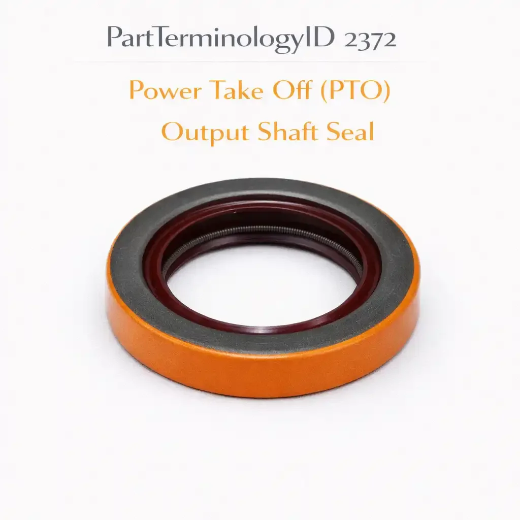
PartTerminologyID 2372, Power Take Off (PTO) Output Shaft Seal, is a rotary lip seal that prevents gear oil from escaping the PTO housing at the point where the output shaft exits the housing toward the driven equipment. That definition places the seal at the final shaft exit in the PTO torque path. It does not specify the PTO unit manufacturer and model designation, the compatible transmission model, the output shaft diameter at the seal contact zone, the housing bore diameter at the seal installation point, the seal width, the lip material, the gear oil compatibility, whether the output shaft is a keyed shaft, a splined shaft, a threaded shaft, or a flanged output, whether the output shaft rotates continuously when the PTO is engaged or only when the driven equipment demands torque through a secondary clutch, what the output shaft surface speed is at the seal contact zone, whether the seal is a single-lip or double-lip design, what the operating environment is at the PTO output end, or whether the seal is accessible with the PTO mounted on the transmission or requires PTO removal. A listing under PartTerminologyID 2372 that specifies fitment without the PTO designation, the output shaft diameter, the bore diameter, and the lip material cannot be evaluated by any technician who has identified an output shaft seal leak and is matching the replacement before beginning the repair.
For sellers, PartTerminologyID 2372 is the terminal seal PartTerminologyID in the PTO torque path. PartTerminologyID 2356 covers the input shaft seal where torque enters the PTO from the transmission. PartTerminologyID 2364 covers the intermediate shaft seal where torque passes between stages within the PTO housing. PartTerminologyID 2372 covers the output shaft seal where torque exits the PTO to the driven equipment. Together, the three PTO shaft seal PartTerminologyIDs cover every rotating shaft exit point in the PTO housing in the sequence of the torque path, and a complete PTO seal replacement service sources from all three in the correct combination for the specific PTO model.
The output shaft position is the most demanding seal position in the PTO for two reasons that do not apply to the input or intermediate positions. First, the output shaft is the shaft that connects directly to the driven equipment, which means the output shaft experiences the full torque reaction of the driven load transmitted back through the shaft to the housing exit. The seal at this position must maintain its contact geometry against the shaft under the vibration and the axial and radial loads that the driven equipment imposes on the output shaft, which are higher and more varied than the loads at the input or intermediate positions. Second, the output shaft exit is the most exposed position on the PTO exterior: it faces the driven equipment, which on a truck-mounted PTO may be a hydraulic pump, an air compressor, a winch drive, or a concrete mixer drum drive, any of which generates vibration and heat that propagates back along the output shaft to the seal contact zone.
For sellers, the listing under this PartTerminologyID is only useful if it specifies the PTO unit designation, the output shaft configuration, the shaft diameter, the bore diameter, the seal width, the lip material, the gear oil compatibility, and the maximum continuous temperature rating. Without those eight attributes, the listing cannot prevent the dimensional mismatch and the fluid or temperature incompatibility failures that drive returns for this PartTerminologyID.
What the PTO Output Shaft Seal Does
Sealing the highest-load shaft exit in the PTO
The output shaft of a PTO is the shaft that delivers the torque from the PTO gear set to the driven equipment. When the driven equipment demands torque, the reaction force is transmitted through the output shaft back to the PTO housing. The seal at the output shaft exit is compressed between the rotating shaft and the stationary housing bore under this reaction force. Unlike the input shaft seal, which experiences a relatively consistent load from the transmission drive gear engagement, the output shaft seal experiences load variations that correspond to the demand cycle of the driven equipment. A concrete mixer that cycles between no-load and full-load torque demand produces a corresponding cycle of low and high reaction force at the output shaft bearing and at the output shaft seal position.
The seal must maintain its lip contact geometry under these variable loads. A seal with a lip that is too stiff will not conform to minor shaft deflections under full load, producing a leak on the side of the bore where the shaft deflects away from the lip. A seal with a lip that is too compliant will extrude under the centrifugal force at the output shaft surface speed and lose its contact interference at high speed. The correct lip design for a PTO output shaft seal is a calibrated balance between contact force, lip stiffness, and surface speed that is specific to the output shaft diameter, the output shaft speed range, and the driven equipment load cycle.
The output shaft configuration and its effect on seal selection
PTO output shafts are produced in several configurations that connect to different driven equipment couplings. The most common configurations are the keyed shaft, the splined shaft, and the flanged output.
A keyed shaft has a flat-bottom keyway machined along the shaft for a portion of its length. The driven equipment coupling slides over the shaft and a key inserted in the keyway transmits the torque. The shaft at the seal contact zone is a cylindrical surface outboard of the keyway end. The seal contacts the full cylindrical surface and the keyway does not extend to the seal contact zone on most designs. However, on some PTO designs where the keyway extends close to or through the seal contact zone, the keyway groove interrupts the continuous cylindrical surface that the seal lip requires, and the seal must be positioned to contact the shaft at a location where the keyway has ended and the full cylindrical surface is restored.
A splined shaft has external splines that engage the internal splines of the driven equipment coupling. The splined section is outboard of the seal contact zone on most PTO designs, and the seal contacts the shaft at the smooth cylindrical section inboard of the spline start. On some compact PTO designs, the splined section begins close to the housing exit, and the seal must be positioned to contact the shaft at the smooth journal between the housing bore and the spline start. The listing must state the position of the smooth journal relative to the housing exit for splined output shaft applications.
A flanged output has a companion flange or a SAE bolt pattern output flange integral to or bolted to the output shaft end. The seal contacts the shaft between the housing bore and the flange. The shaft surface at the seal contact zone is the cylindrical journal of the output shaft between the bearing land and the flange face.
The output shaft surface speed and its relationship to the gear oil pressure at the seal
The output shaft of a PTO rotates at the speed determined by the PTO gear ratio and the transmission output speed. On a direct-drive single-stage PTO, the output shaft rotates at the same speed as the input shaft. On a reduction PTO, the output shaft rotates more slowly than the input shaft. On a step-up PTO used to drive high-speed equipment such as air compressors, the output shaft may rotate faster than the input shaft.
The gear oil pressure at the output shaft bearing cavity is affected by the output shaft speed and the oil throw-off from the PTO gears. At high output shaft speeds, the rotating gears create an oil mist and a centrifugal oil flow toward the outer walls of the housing. The output shaft exit bore at the housing outer wall receives this centrifugal oil flow and the seal at this bore must resist a higher effective oil pressure than the static head pressure that acts on the seal at low shaft speeds. A seal with an inadequate garter spring contact force for the output shaft speed will be overwhelmed by the centrifugal oil pressure and leak at the shaft contact zone.
The listing must state the output shaft speed range at the seal contact zone and confirm the seal is rated for the maximum output shaft speed at the PTO's rated operating speed.
The driven equipment environment and the double-lip seal requirement
The PTO output shaft exits the housing toward the driven equipment, which means the outboard face of the output shaft seal is exposed to whatever environment surrounds the driven equipment. On a truck-mounted hydraulic pump driven by the PTO, the output shaft seal outboard face is adjacent to the hydraulic pump's suction port area, which is subject to hydraulic oil mist and the heat from the hydraulic system. On a concrete mixer drive, the output shaft seal outboard face is exposed to concrete dust, water, and vibration from the mixer mechanism. On an agricultural implement drive, the output shaft seal outboard face may be exposed to mud, crop debris, water, and fertilizer spray.
A single-lip seal at the PTO output shaft position seals the gear oil inside the PTO against the driven equipment environment. It does not prevent contamination from the driven equipment environment from entering the PTO housing along the output shaft. A double-lip seal with an exclusion lip prevents both gear oil escape and contamination ingress simultaneously. For any PTO application where the driven equipment environment contains significant contamination, a double-lip seal is the correct specification regardless of the cleanliness of the PTO gear oil circuit.
The output shaft seal and the SAE output flange standard
Some PTO output connections use an SAE bolt pattern output flange rather than a keyed or splined shaft. The SAE output flange standard defines the bolt circle diameter, the bolt count, and the pilot bore diameter for each SAE output size class. On flanged output PTOs, the output shaft seal is at the shaft journal between the housing bore and the flange face, and the seal must be installed and the flange seated against the housing before the driven equipment is connected.
The seal specification for a flanged output PTO must state the shaft journal diameter at the seal contact zone and the bore diameter in the housing, because the SAE flange size does not uniquely determine the shaft journal dimensions. Two PTOs with the same SAE flange size may have different shaft journal diameters if the flange is bolted to different output shaft designs.
The Specifications That Determine Correct Seal Fitment
PTO unit designation and transmission model
The PTO unit designation is the primary fitment attribute. It determines the output shaft configuration, the output shaft speed range, and the gear oil specification. The compatible transmission model confirms the input speed to the PTO, which determines the output shaft speed at rated PTO operating conditions.
Output shaft configuration
Keyed, splined, or flanged. For keyed and splined outputs, state the keyway or spline position relative to the seal contact zone. For flanged outputs, state the SAE flange class alongside the shaft journal diameter.
Shaft diameter and bore diameter
State in millimeters to two decimal places. The output shaft diameter at the seal contact zone is typically the largest shaft diameter in the PTO housing because the output shaft must carry the full torque output of the unit and is sized accordingly.
Seal width
In millimeters. The available bore depth at the output shaft housing wall determines the maximum usable seal width. The output shaft bore is typically in the main housing casting opposite the PTO mounting face, which is the most accessible face of the PTO for seal replacement.
Lip material and gear oil compatibility
Nitrile for conventional GL-4 and GL-5 mineral gear oil. HNBR for synthetic gear oil or high-temperature driven equipment environments. Polyacrylate for full-synthetic gear oil on extended commercial service intervals. State the API GL rating and mineral or synthetic specification.
Maximum continuous temperature rating
State in degrees Celsius. The driven equipment heat contribution to the output shaft seal environment requires an explicit temperature rating alongside the lip material, because the same lip material may be adequate at the input shaft position and inadequate at the output shaft position on the same PTO if the driven equipment runs hot.
Output shaft speed range
State the output shaft speed range from zero to rated PTO speed in RPM. Confirm the seal is rated for the maximum output shaft speed in terms of both lip surface speed in m/s and garter spring contact force at maximum centrifugal loading.
Single-lip versus double-lip with exclusion
Single-lip for clean indoor or protected driven equipment environments. Double-lip with exclusion for contaminated driven equipment environments including concrete, agricultural, municipal, and off-road applications.
Why This Part Generates Returns
Buyers order the wrong PTO output shaft seal because:
the PTO unit designation is not specified and the output shaft diameter does not match the replacement seal inner diameter
the output shaft configuration is not stated and the keyway interrupts the seal contact zone on the replacement shaft but not on the original, or the spline start position is different
the lip material is not rated for the driven equipment heat contribution at the output shaft position and hardens at the combined PTO operating temperature plus driven equipment ambient temperature
the seal is a single-lip design used in a contaminated driven equipment environment that requires the exclusion lip of a double-lip design
the garter spring contact force is insufficient for the centrifugal oil pressure at the rated output shaft speed and the seal leaks at high PTO speed but seals at idle
the seal width exceeds the bore depth at the output shaft housing wall and the driven equipment coupling flange cannot seat against the housing face
Status in New Databases
PIES/PCdb: PartTerminologyID 2372, Power Take Off (PTO) Output Shaft Seal
PIES 8.0 / PCdb 2.0: No change
Top Return Scenarios
Scenario 1: "Keyway extends through seal contact zone, lip torn on installation over keyway edge"
The PTO output shaft has a keyway that extends from the shaft end to within 5mm of the housing bore. The replacement seal is pressed onto the shaft from the driven equipment side, passing over the keyway edge before reaching the seal contact zone. The keyway edge catches the seal lip during installation and tears a section of the lip. The torn lip cannot maintain contact circumferentially and the seal leaks immediately.
Prevention language: "Output shaft keyway position: [keyway ends [X]mm from housing bore face / keyway does not extend into seal contact zone]. Seal installation requires pressing the seal over the keyed section of the shaft. Use a seal installation tool with a tapered lead-in that bridges the keyway opening and prevents the seal lip from catching the keyway edge during installation. A torn seal lip cannot be detected until the seal leaks under operating pressure."
Scenario 2: "Seal leaks at rated PTO speed, seals at idle, garter spring insufficient for centrifugal oil pressure"
The PTO output shaft runs at 1,800 RPM at rated PTO operating speed. The output shaft diameter is 38mm. The lip surface speed at rated speed is approximately 3.6 m/s. At rated speed, the centrifugal oil throw from the PTO gears pressurizes the output shaft bore above the static head pressure. The replacement seal's garter spring contact force is calibrated for static head pressure only and is insufficient to maintain lip contact against the centrifugal oil pressure at 1,800 RPM. The seal seals correctly at PTO idle and begins leaking above approximately 1,200 RPM.
Prevention language: "Output shaft rated speed: [X] RPM. Lip surface speed at rated speed: [X] m/s. Garter spring contact force specification: rated for centrifugal oil pressure at [X] RPM maximum. Verify the replacement seal is rated for the output shaft's maximum operating speed, not only for static oil head pressure. A seal with insufficient garter spring contact force for the centrifugal oil pressure at rated speed will seal at low speed and leak above the speed at which the centrifugal pressure exceeds the spring contact force."
Scenario 3: "Single-lip seal, concrete plant PTO, concrete dust contamination destroyed gear oil within 3,000 miles"
The PTO drives a concrete mixer drum on a transit mixer truck. The output shaft is exposed to concrete dust, water, and cement slurry during every mixing cycle. The replacement seal is a single-lip design that retains the gear oil but does not exclude contamination. Concrete dust entered the PTO housing along the output shaft from the driven equipment side. The concrete dust contaminated the gear oil, increased its abrasiveness, and accelerated the bearing and gear wear to the point of PTO failure within 3,000 miles of replacement.
Prevention language: "Seal lip configuration: [single-lip / double-lip with exclusion lip]. Application environment: [concrete plant / construction / agricultural / municipal]. This PTO is used in a contaminated driven equipment environment. A single-lip seal retains gear oil but does not prevent contamination from entering the PTO along the output shaft. For concrete, construction, agricultural, or municipal applications, specify a double-lip seal with an exclusion lip at the output shaft position."
Scenario 4: "Driven equipment heat contribution, nitrile limit exceeded, lip hardened at output position while input seal intact"
A hydraulic pump driven by the PTO generates significant heat during sustained full-load operation. The ambient temperature at the PTO output shaft position, which is adjacent to the hydraulic pump body, reaches 125 degrees Celsius during sustained hydraulic work cycles. The input shaft position, which faces the transmission, remains at 90 degrees Celsius. Both seals were replaced with standard nitrile. The input seal remains serviceable. The output seal hardened and lost contact interference within 15,000 miles because the output position ambient temperature exceeded the 110 degree nitrile limit.
Prevention language: "Maximum continuous temperature at output shaft position: [X] degrees Celsius. Note: the output shaft position is adjacent to the driven equipment and is subject to heat contribution from the driven equipment in addition to the PTO operating temperature. Verify the ambient temperature at the output shaft position under your specific driven equipment's full-load operating conditions. If the temperature exceeds 110 degrees Celsius, specify an HNBR seal rated to 150 degrees Celsius for the output shaft position even if the input shaft position uses a standard nitrile seal."
Scenario 5: "Seal too wide, driven equipment coupling flange cannot seat against PTO housing"
The replacement seal is 6mm wider than the original. The seal protrudes 6mm beyond the output shaft housing wall face. The driven equipment coupling flange that bolts to the PTO output face cannot seat flat against the housing face with the protruding seal. The coupling flange is torqued against the protruding seal and the seal is compressed beyond its design range. The over-compressed seal lip geometry is distorted and the seal leaks within the first operating cycle.
Prevention language: "Seal width: [X]mm. Available bore depth at output shaft position: [X]mm. Verify the seal width does not exceed the bore depth. A seal wider than the bore depth protrudes from the housing face and prevents the driven equipment coupling flange from seating correctly. Over-compression from a forced coupling installation distorts the seal lip geometry and produces an immediate leak."
What to Include in the Listing
Core essentials
PartTerminologyID: 2372
component: PTO Output Shaft Seal
PTO unit manufacturer and model designation (mandatory)
compatible transmission model (mandatory)
output shaft configuration: keyed, splined, or flanged (mandatory)
keyway or spline position relative to seal contact zone for keyed and splined shafts (mandatory)
SAE flange class for flanged outputs (mandatory)
shaft diameter at seal contact zone in mm to two decimal places (mandatory)
housing bore diameter in mm to two decimal places (mandatory)
seal width in mm (mandatory)
available bore depth in mm (mandatory)
lip material: nitrile, HNBR, or polyacrylate (mandatory)
gear oil compatibility: API GL rating and mineral or synthetic (mandatory)
maximum continuous temperature rating in degrees Celsius (mandatory)
output shaft speed range in RPM (mandatory)
lip surface speed at rated speed in m/s (mandatory)
garter spring contact force specification: static head only or centrifugal rated (mandatory)
lip configuration: single-lip or double-lip with exclusion lip (mandatory)
driven equipment environment: clean, hydraulic oil mist, concrete, agricultural, municipal (mandatory for double-lip specification guidance)
shaft surface finish requirement in Ra micrometers (mandatory)
access for replacement: PTO mounted or PTO removal required (mandatory)
quantity: 1
Fitment essentials
commercial vehicle year/make/model or equipment designation
PTO unit designation (primary fitment attribute)
compatible transmission model
driven equipment type for lip configuration selection
output shaft configuration for keyway and spline position verification
Dimensional essentials
shaft diameter at seal contact zone in mm to two decimal places
seal inner diameter before installation in mm
housing bore diameter in mm
seal outer diameter in mm
seal width in mm
available bore depth in mm
press fit interference in mm
lip contact band width in mm
garter spring inner diameter in mm
keyway width and depth if keyway is present at or near seal contact zone
Image essentials
seal in isolation showing lip configuration: single-lip or double-lip with exclusion
cross-section showing inner lip, garter spring, and exclusion lip arrangement
output shaft shown with keyway position, spline start position, or flange configuration visible
smooth journal section of the output shaft identified as the seal contact zone
housing output bore shown with available bore depth callout
driven equipment coupling shown alongside the PTO output for context on the seal position relative to the coupling interface
installation tool shown for keyed shaft applications demonstrating the tapered lead-in that bridges the keyway
Catalog Checklist for ACES/PIES Teams
PartTerminologyID = 2372
require PTO unit designation (mandatory)
require compatible transmission model (mandatory)
require output shaft configuration: keyed, splined, or flanged (mandatory)
require keyway or spline position relative to seal contact zone (mandatory)
require shaft diameter in mm to two decimal places (mandatory)
require housing bore diameter in mm (mandatory)
require seal width and bore depth (mandatory)
require lip material with temperature rating (mandatory)
require gear oil compatibility (mandatory)
require output shaft speed range and lip surface speed at rated speed (mandatory)
require garter spring rating: static head only or centrifugal rated (mandatory)
require lip configuration with driven equipment environment note (mandatory)
require access requirement (mandatory)
complete the PTO torque path seal series: PartTerminologyID 2356 covers the input shaft seal; PartTerminologyID 2364 covers the intermediate shaft seal; PartTerminologyID 2372 covers the output shaft seal; a complete PTO seal replacement service sources all three PartTerminologyIDs in the correct specifications for the PTO model; the cross-reference between the three PartTerminologyIDs in each listing helps the buyer who is doing a complete seal service source all three positions in one purchase decision
differentiate from PTO intermediate shaft seal (PartTerminologyID 2364): the intermediate shaft seal is at an internal shaft within the PTO housing between the input and output stages; the output shaft seal is at the final shaft exit toward the driven equipment; the output shaft is typically the largest-diameter shaft in the PTO and has the highest torque loading
differentiate from PTO mounting gasket (PartTerminologyID 2324): the mounting gasket is at the transmission-side face; the output shaft seal is at the driven equipment-side face; both contain gear oil within the PTO but from different interface types at opposite ends of the housing
differentiate from PTO countershaft seal (PartTerminologyID 2340): the countershaft is an intermediate shaft within the housing; the output shaft exits the housing toward the driven equipment; both are rotating shaft seals within the PTO but the output shaft seal is the terminal seal in the torque path
flag driven equipment heat contribution as mandatory for temperature rating: the output shaft position is the only PTO seal position exposed to driven equipment heat, which can elevate the ambient temperature above the nitrile limit; this attribute does not exist at the input or intermediate positions and is unique to the output shaft listing
flag garter spring centrifugal rating as mandatory: a seal with static-only garter spring contact force leaks above a specific PTO output shaft speed; this failure mode is specific to the output shaft position where shaft speed and centrifugal oil pressure are highest in the PTO
flag keyway position as mandatory: a keyway that extends through the seal contact zone tears the seal lip during installation without any warning; this failure is invisible until the PTO is operated and leaks
flag double-lip requirement for contaminated driven equipment environments: the output shaft seal is the only PTO seal position exposed to the driven equipment environment from the outside; contamination exclusion at this position protects the entire PTO gear oil circuit from external contamination ingress
FAQ (Buyer Language)
How do I determine the output shaft speed on my PTO?
The output shaft speed depends on the PTO gear ratio and the transmission output shaft speed at your typical operating condition. The PTO gear ratio is published in the PTO specification sheet or the parts catalog. A typical direct-drive PTO ratio is 1.0, meaning the output speed equals the transmission output speed. A reduction PTO may have a ratio of 0.65 to 0.85, producing an output speed that is 65 to 85 percent of the transmission output speed. A step-up PTO may have a ratio above 1.0. Multiply the transmission output speed at your typical PTO engagement RPM by the PTO ratio to get the output shaft speed. For a vehicle with a 6-speed automatic transmission typically running at 1,500 engine RPM in the PTO engagement gear, the transmission output speed at that condition is the engine RPM divided by the torque converter ratio and the gear ratio. Your truck's operating manual or the transmission service data will give you the transmission output speed at the operating condition.
My PTO output shaft has a keyway. Do I need a special tool to install the seal over the keyway?
Yes. A seal lip that is pressed directly over a keyway edge during installation will catch the keyway corner and either tear the lip or fold it under as the seal advances over the shaft. A seal installation tool with a tapered sleeve or a thin-walled installation cone that covers the keyway opening allows the seal to pass over the keyed section without lip contact with the keyway edge. Some seal manufacturers include a plastic installation sleeve with the seal for keyed shaft applications. If a sleeve is not provided, fabricate a thin sheet metal cone that covers the keyway and allows the seal to slide over the shaft smoothly. Remove the installation sleeve or cone before the seal reaches its final position.
My PTO output seal leaks only under full hydraulic pump load and seals when the pump is at low pressure. What is causing this?
A leak that appears under full driven equipment load and stops at low load is consistent with one of two mechanisms. First, the output shaft may be deflecting radially under the full torque reaction of the hydraulic pump, causing the shaft to contact the seal lip eccentrically and open a leak path on the opposite side. This is a bearing wear or output shaft support issue that a seal replacement alone will not address. Second, the gear oil pressure in the PTO output shaft bearing cavity may rise under full PTO load from the gear oil throw-off at high output shaft speed, exceeding the garter spring contact force of the seal. In that case, the seal requires a higher garter spring contact force specification or an HNBR lip material with higher stiffness at operating temperature. Both possibilities must be investigated before ordering the replacement seal.
The PTO service manual specifies replacing all three shaft seals at every major service. Does that mean I should replace the input and intermediate seals when I replace the output seal?
Yes, if the PTO is being opened for output shaft seal replacement, the input shaft seal and any intermediate shaft seals should be replaced at the same service event. The three seals were installed at the same time and have accumulated the same operating hours. A seal that is close to its service limit at the time of an adjacent seal replacement will fail shortly after the PTO is returned to service, requiring another removal and disassembly for what could have been addressed at the same event. The labor cost of a complete three-seal service at a single disassembly event is significantly less than three separate removal events for individual seal failures.
What is the correct press-fit procedure for the PTO output shaft seal in the housing bore?
Clean the housing bore thoroughly and remove any remnants of the original seal, including any sealant applied to the outer diameter of the original seal. Lightly coat the new seal outer diameter with the same gear oil used in the PTO. Do not apply RTV or gasket sealant to the seal outer diameter unless the PTO service manual specifically requires it: most press-fit seals achieve their outer diameter sealing through the interference fit alone and sealant on the outer diameter can prevent the seal from achieving the full press-fit contact. Use a seal driver that contacts only the outer rim of the seal face and drive the seal squarely into the bore to the correct depth. Verify with a depth gauge that the seal face is at the specified installation depth before assembling the driven equipment coupling.
Cross-Sell Logic
PTO Input Shaft Seal (PartTerminologyID 2356: replace concurrently with the output seal at every complete PTO seal service)
PTO Intermediate Shaft Seal (PartTerminologyID 2364: replace concurrently for multi-stage PTOs at every complete seal service)
PTO Output Shaft Bearing (the output shaft bearing is adjacent to the output shaft seal and is the component most likely to have been damaged if the output seal failed and allowed gear oil to escape from the output shaft cavity; inspect and replace concurrently)
PTO Mounting Gasket (PartTerminologyID 2324: inspect and replace at every PTO removal event)
PTO Gear Oil (drained and replaced at every PTO opening; confirm the correct API GL rating, viscosity, and synthetic or mineral specification)
PTO Gasket Set (if all seals and gaskets are being replaced at a complete service event, a full gasket set is more efficient than ordering individual components)
Driven Equipment Coupling (the coupling that connects the driven equipment to the PTO output shaft is inspected for wear at the shaft contact surfaces when the seal is replaced; worn coupling bore surfaces allow the shaft to wobble and defeat the new seal)
Frame as "the output shaft seal retains the gear oil at the last shaft exit before the driven equipment. The output shaft bearing supports the shaft the seal contacts. The gear oil lubricates the bearing and gears the seal protects. The input shaft seal and the intermediate shaft seal are at the other two seal positions in the same housing. All are replaced together at a complete seal service."
Final Take for PartTerminologyID 2372
PTO Output Shaft Seal (PartTerminologyID 2372) completes the three-PartTerminologyID PTO shaft seal sequence that begins at the transmission with the input shaft seal (2356) and passes through the intermediate shaft with the intermediate shaft seal (2364). The output shaft seal is the terminal seal in that sequence and the most demanding position of the three for two reasons that are unique to the output shaft: the driven equipment heat contribution and the centrifugal oil pressure at rated output shaft speed.
The driven equipment heat contribution makes the temperature rating mandatory in a way that does not exist at the input or intermediate positions. The same PTO can have a serviceable nitrile input seal and a failed HNBR output seal at the same mileage if the driven equipment runs hot enough to elevate the output shaft ambient temperature above the nitrile limit while the input shaft ambient temperature stays within it. A listing that states only the lip material without the temperature rating cannot communicate this position-specific temperature requirement.
The centrifugal oil pressure at rated output shaft speed makes the garter spring contact force rating mandatory in a way that also does not exist at the input or intermediate positions, because the output shaft is the fastest rotating shaft in a reduction PTO and generates the highest centrifugal oil pressure at the housing exit. A seal that seals at idle and leaks at rated speed is a seal with a static-head-only garter spring at a centrifugal-pressure position, and the listing that does not specify the garter spring rating cannot prevent that failure.
State the PTO unit designation and output shaft configuration. State the shaft diameter and bore diameter. State the seal width and bore depth. State the lip material with the temperature rating. State the gear oil compatibility. State the output shaft speed and lip surface speed. State the garter spring rating. State the lip configuration with the driven equipment environment note. State the access requirement. That is the same listing strategy as every other PartTerminologyID in this series: specific attributes at every level to become a listing the commercial vehicle technician can evaluate and act on. For PartTerminologyID 2372, the temperature rating and the garter spring rating are the two attributes that distinguish the output shaft seal from the other two PTO shaft seals in the torque path series and that cannot be omitted without leaving the listing unable to prevent the two failure modes unique to this position.