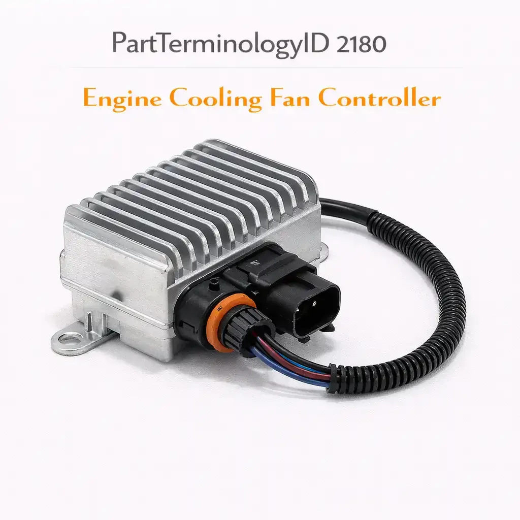
Engine Cooling Fan Controller (PartTerminologyID 2180): The Module Where Control Strategy and Connector Configuration Both Determine Whether the Replacement Works
Written by Arthur Simitian | PartsAdvisory
PartTerminologyID 2180, Engine Cooling Fan Controller, is a module or device that controls the operation of the engine cooling fan. That definition identifies the function without specifying the control strategy the module uses, the input signals it requires to operate, the output it sends to the fan motor, the connector pin count and configuration, whether the module is a standalone unit or integrated into the body control module, whether the replacement requires programming after installation, or which vehicle and engine the module is calibrated for. A listing under PartTerminologyID 2180 that does not specify the control strategy, the connector configuration, and whether programming is required is asking the buyer to guess whether the replacement module will communicate correctly with the vehicle's other control modules and whether the fan will operate at the speeds the thermal management system requires.
For sellers, the engine cooling fan controller is an electronic component where a fitment error produces a failure mode that is harder to diagnose than most mechanical cooling failures. A wrong thermostat produces overheating. A wrong fan motor produces a blown fuse or reversed airflow. A wrong fan controller may produce a fan that runs at only one speed on a multi-speed system, a fan that does not respond to air conditioning activation, a fan that triggers a fault code in the engine control module, or a fan that runs continuously at full speed regardless of coolant temperature. Each of those symptoms sends the buyer back into a diagnostic process, because the fault is not obviously the replacement module. The buyer may replace the coolant temperature sensor, the fan motor relay, and the fan motor before identifying the controller as the root cause.
For sellers, the listing under this PartTerminologyID is only useful if it includes the vehicle fitment by engine code, the control strategy, the connector pin count and configuration, the input signal types the module requires, the output signal or voltage it sends to the fan motor, and whether programming or initialization is required after installation. Without those six attributes, the listing ships a module that may not be compatible with the vehicle's thermal management system even when it physically installs in the correct location.
What the Engine Cooling Fan Controller Does
Managing fan speed relative to thermal load
The cooling fan controller's primary function is to vary the fan motor speed in response to thermal inputs from the vehicle's sensor network. On the simplest systems, the controller receives a signal from the coolant temperature sensor and switches the fan relay on at a threshold temperature and off below it. On more sophisticated systems, the controller receives inputs from the coolant temperature sensor, the air conditioning pressure transducer, the intake air temperature sensor, and in some cases the transmission fluid temperature sensor, and modulates the fan speed continuously across a range rather than switching between on and off.
A controller that can only switch between on and off installed on a system that was designed for continuous speed modulation will run the fan at full speed whenever the coolant temperature exceeds the activation threshold, regardless of whether full-speed operation is needed. The result is reduced fuel economy from the fan's parasitic load, increased fan motor wear from continuous high-speed operation, and potential overcooling of the coolant in moderate ambient temperatures.
The relay-based controller versus the solid-state module
The simplest fan controllers are relay-based: an electromechanical relay switches the fan circuit on and off in response to a control signal from the engine control module or directly from a temperature switch. The relay is the controller in this architecture. When the relay fails, the fan does not operate. Relay-based fan controllers are the most common design on vehicles produced before approximately 2005 and on many current-production vehicles with simple single-speed fan systems.
Solid-state fan control modules use transistor or MOSFET switching rather than electromechanical relays to control fan speed. They can operate the fan at variable speeds, respond to PWM signals from the engine control module, and provide fault detection feedback to the control network. Solid-state modules are the dominant design on vehicles produced after 2008 and are standard on all vehicles with multi-speed or PWM-controlled fan systems.
The listing must specify whether the replacement is a relay-based or solid-state design. A solid-state replacement on a relay-based circuit will not receive the correct control signals. A relay replacement on a solid-state circuit will not provide variable speed control.
The PWM fan control module
The most current fan control architecture uses pulse-width modulation. The engine control module sends a PWM signal to the fan control module specifying the desired fan speed as a percentage of maximum speed. The fan control module converts that signal into the appropriate voltage or current to drive the fan motor at the commanded speed. The fan tachometer signal from the motor feeds back to the control module, which adjusts the output to maintain the commanded speed against varying resistance from blade loading and airflow conditions.
A replacement PWM fan control module must respond to the same PWM signal frequency and duty cycle range that the vehicle's ECM produces. A module calibrated for a different PWM frequency will not operate the fan at the commanded speed. A module that does not support the tachometer feedback circuit will not provide speed confirmation to the ECM, which will generate a fan speed fault code.
Programming and initialization requirements
On vehicles where the fan control module communicates on the CAN bus or the LIN bus with the engine control module, body control module, and climate control module, a replacement module may require initialization or programming after installation. The initialization process writes the vehicle's VIN, the calibration data for the specific fan motor and thermal management system, and the communication parameters into the replacement module. Without initialization, the replacement module may communicate on the bus with incorrect parameters, generate fault codes, or operate in a default mode that does not match the vehicle's thermal management strategy.
Programming requirements are not uniformly disclosed in aftermarket listings. A buyer who purchases a module expecting a plug-and-play replacement and discovers on installation that the module requires dealer-level programming tools to complete the installation has a return and a diagnostic appointment ahead of them. The programming requirement must be disclosed in the listing.
The Controller Specifications This Part Must Match
Control strategy and signal type
The control strategy determines what input the module accepts and what output it produces. Input types include a direct coolant temperature switch signal, an analog voltage from the ECM, a PWM signal from the ECM, and a digital command over the CAN bus. Output types include direct relay switching, a PWM output to the fan motor, and an analog voltage output. The replacement module must accept the same input type and produce the same output type as the original. Mismatched signal types produce a module that physically installs but does not communicate.
Connector pin count and pin layout
The fan control module connects to the vehicle wiring harness through a multi-pin connector. The pin count and pin layout must match the harness connector exactly. Common pin counts for fan control modules range from 4 pins on simple relay-based designs to 12 or more pins on PWM-controlled modules with tachometer feedback, fault signal output, and multiple motor output channels. A module with the correct pin count but a different pin layout will connect to the harness but will apply signals to the wrong circuits, which can damage the module, the fan motor, or the wiring harness.
Operating voltage and current capacity
The module must be rated for the vehicle's operating voltage, which is 12V DC on passenger vehicles and 24V DC on heavy-duty applications. The current capacity of the module's output stage must equal or exceed the fan motor's maximum current draw. A module with insufficient current capacity will overheat its output stage under sustained high-speed fan operation, producing a gradual performance degradation that manifests as progressively slower fan speeds until the module fails.
Mounting location and thermal management
Fan control modules generate heat during operation and must be mounted in a location that provides adequate thermal dissipation. Most OE modules are mounted on the fan shroud or the radiator support where they receive airflow when the vehicle is in motion. A replacement module that cannot be mounted in the same location as the original, or that has a different mounting configuration, may operate at higher temperatures than designed and fail prematurely.
Why This Part Generates Returns
Buyers order the wrong engine cooling fan controller because:
the control strategy is not stated and the replacement is a relay-based module on a PWM-controlled system, producing a fan that operates at one speed only
the connector pin count matches but the pin layout is different, causing incorrect signal routing and fan or module damage
the programming requirement is not disclosed and the buyer discovers after installation that the module requires dealer programming tools to initialize
the vehicle and engine code are not specified and the same vehicle platform uses different fan control modules on different engine variants or different production years
the replacement module is not compatible with the vehicle's CAN bus communication protocol and generates persistent fault codes after installation
the current capacity is insufficient for the fan motor and the output stage fails under sustained operation
the listing does not distinguish between a cooling fan relay and a cooling fan controller module, and the buyer receives a relay when they need a solid-state control module
Status in New Databases
PIES/PCdb: PartTerminologyID 2180, Engine Cooling Fan Controller
PIES 8.0 / PCdb 2.0: No change
Top Return Scenarios
Scenario 1: "Fan only runs at full speed, no variable control"
The replacement module is a relay-based on/off design. The vehicle's original module was a PWM-controlled variable-speed design. The fan operates at full speed whenever the activation threshold is reached and does not modulate. The buyer returns the module after a scan tool shows a fan speed control fault code.
Prevention language: "Control strategy: [relay on/off / multi-speed / PWM variable speed]. This module provides [relay on/off / PWM variable speed] fan control. Verify your vehicle's fan control system requires [this control strategy] before ordering. A relay-based module installed on a PWM-controlled system will not provide variable fan speed."
Scenario 2: "Module installed correctly but requires dealer programming"
The replacement module requires initialization through a dealer-level programming interface. The buyer was not informed of this requirement in the listing. The fan does not operate correctly after installation and the module generates fault codes until programmed.
Prevention language: "Programming required after installation: [yes / no]. This module requires initialization using [dealer-level programming tools / a compatible scan tool with module programming capability] before the fan will operate correctly. Verify you have access to the required programming tools before ordering."
Scenario 3: "Wrong connector layout, signals routed to wrong pins"
The pin count matches. The pin layout does not. The PWM signal wire is connected to the motor output pin on the replacement module and the motor output wire is connected to the PWM input pin. The module does not respond to the ECM's control signal and the fan does not operate.
Prevention language: "Connector: [X]-pin [connector description]. Pin layout must match your vehicle harness connector exactly. A connector with the correct pin count but a different pin layout will apply signals to incorrect circuits. Verify the pin layout using the vehicle wiring diagram before connecting."
Scenario 4: "Persistent fault codes after installation"
The replacement module communicates on a different CAN bus address or uses a different communication protocol than the original. The ECM receives unexpected messages from the replacement module and generates communication fault codes that cannot be cleared without restoring the original module.
Prevention language: "CAN bus compatibility: verified for [year range, make, model, engine code]. This module is pre-programmed for [these applications]. Installing this module on a vehicle outside the listed application range may produce CAN bus communication faults that require dealer diagnostic equipment to resolve."
Scenario 5: "Module failed within 6 weeks of installation"
The replacement module's output current capacity was insufficient for the fan motor's peak current draw on a hot day with the air conditioning active. The output stage overheated on sustained full-speed operation and failed.
Prevention language: "Output current capacity: [X] amperes continuous, [X] amperes peak. Verify the output current capacity meets or exceeds the maximum current draw of your fan motor under the highest-load conditions the vehicle will experience."
What to Include in the Listing
Core essentials
PartTerminologyID: 2180
component: Engine Cooling Fan Controller
control strategy: relay on/off, multi-speed, or PWM variable speed (mandatory)
module type: relay, solid-state transistor, or solid-state PWM (mandatory)
programming required after installation: yes or no (mandatory)
connector pin count (mandatory)
input signal type: temperature switch, analog ECM signal, PWM, or CAN bus command (mandatory)
output signal type: relay switching, PWM to motor, or analog voltage to motor (mandatory)
operating voltage: 12V or 24V DC
output current capacity in amperes
mounting configuration: shroud mount, bracket mount, or chassis mount
quantity: 1
Fitment essentials
year/make/model/submodel
engine code (mandatory when fan control module specification varies by engine within the same model)
production date range when the module changed during the model year
OE part number cross-reference when available
compatible ECM or BCM part number for bus-communicating modules
Dimensional essentials
module body dimensions in mm
mounting bracket hole spacing in mm
connector body dimensions for harness connector fitment verification
Image essentials
module in isolation showing body, connector, and mounting bracket
connector close-up showing pin count and pin layout
mounting bracket detail showing hole pattern
label or nameplate showing part number and any programming codes
installed context showing the module in position on the fan shroud or radiator support
Catalog Checklist for ACES/PIES Teams
PartTerminologyID = 2180
require control strategy: relay, multi-speed, or PWM (mandatory)
require module type: relay or solid-state
require programming requirement disclosure: yes or no (mandatory)
require connector pin count (mandatory)
require input and output signal types
require output current capacity in amperes
require engine code when specification varies by engine on the same platform
require production date range when module specification changed mid-model-year
differentiate from engine cooling fan motor (PartTerminologyID 2164): the motor is the load; the controller manages that load; both may need replacement when the fan system fails but they are separate parts
differentiate from engine cooling fan relay (PartTerminologyID varies): a relay is an electromechanical switch; a fan controller module may contain a relay or may use solid-state switching; when the failed component is the relay within the module, the entire module is replaced on integrated designs
differentiate from engine coolant temperature sensor (PartTerminologyID varies): the sensor provides the thermal input the controller responds to; a failed sensor may prevent the controller from activating the fan; verify the sensor before replacing the controller
differentiate from body control module or engine control module integration (PartTerminologyID varies): on some vehicles, fan control logic is integrated into the BCM or ECM; on those vehicles, there is no standalone fan control module under PartTerminologyID 2180
flag programming requirements: this is the most consequential undisclosed attribute for electronic modules because it requires tools most DIY buyers do not have
flag CAN bus compatibility: a module that communicates on the wrong bus address generates persistent fault codes that cannot be resolved without restoring the original module or reprogramming the replacement
FAQ (Buyer Language)
How do I know what type of fan controller my vehicle uses?
Consult the factory service manual's cooling system and electrical diagrams for your engine code and production year. The fan control section will specify whether the system uses a direct relay, a multi-speed resistor module, or a PWM-controlled solid-state module. A scan tool with live data capability can also show the fan speed command from the ECM and the actual fan speed from the tachometer feedback circuit, which tells you whether the system is capable of variable speed control.
What does it mean when a fan controller requires programming?
It means the module must have vehicle-specific data written into its memory by a programming tool before it will operate correctly. This data typically includes the vehicle identification number, the calibration parameters for the fan motor and the thermal management system, and the communication addresses the module uses on the CAN bus. Without programming, the module may default to a fixed operating mode, fail to communicate with other modules, or generate fault codes. Programming is typically performed with a dealer-level scan tool or a compatible aftermarket programming interface.
My fan runs continuously at full speed. Is the controller the problem?
Not necessarily. A fan that runs continuously at full speed can be caused by a stuck-closed relay in the fan circuit, a failed temperature sensor sending a constant high-temperature signal, a short in the fan circuit wiring, or a failed controller that is outputting maximum drive signal continuously. Before replacing the controller, check the coolant temperature sensor live data on a scan tool to verify it is reading correctly, check the fan relay for stuck contacts, and check for fault codes that point to the controller specifically. A controller that outputs continuous full speed may be responding to a constant maximum-temperature signal from a failed sensor rather than failing internally.
Can I use a relay instead of the original solid-state fan controller module to simplify the system?
On older vehicles with simple wiring, this is sometimes done as a modification. On current-production vehicles with CAN bus integration and fault monitoring, bypassing the original solid-state controller with a relay will produce persistent fault codes from the ECM for missing fan speed feedback, missing fan controller communication, and fan speed out-of-range. The ECM may also reduce engine power or activate a limp mode to protect the engine from potential overheating if it cannot confirm fan operation through the expected feedback circuit. This is not a recommended repair on any vehicle built after approximately 2010.
My fan controller has a part number from a different brand than the original. Does that matter?
Brand alone does not determine fitment. Verify the control strategy, the connector pin count and layout, and the programming requirements match your original. An aftermarket replacement from a different brand that matches all three specifications will function correctly. An aftermarket replacement that differs in any of those specifications will produce the failure modes described in this listing regardless of brand reputation.
Cross-Sell Logic
Engine Cooling Fan Motor (PartTerminologyID 2164: a failed controller may have operated the fan motor at incorrect voltages or current levels that damaged the motor windings; inspect the motor when the controller is replaced and replace both if the motor shows signs of thermal damage)
Engine Cooling Fan Relay (PartTerminologyID varies: on systems where the controller operates through a separate relay, the relay should be inspected and replaced if it shows signs of contact wear or thermal damage from overcurrent events that may have contributed to the controller failure)
Engine Coolant Temperature Sensor (PartTerminologyID varies: the temperature sensor is the primary input to the fan controller; a failed sensor that sent constant maximum-temperature signals may have driven the fan at full speed continuously and overheated the controller's output stage)
Radiator (PartTerminologyID 2172: if the fan controller failure resulted in extended periods of reduced or no fan operation, the radiator should be inspected for heat damage and the coolant should be tested for signs of an overheating event)
Scan Tool or Code Reader (diagnosing a fan controller failure and verifying the replacement operates correctly requires a scan tool with live data and fault code capability; recommend a compatible scan tool to buyers who do not have one)
Engine Coolant (if the controller failure caused an overheating event, the coolant should be tested and replaced if it shows signs of overheating degradation)
Frame as "the controller commands the motor. The relay switches the circuit the motor runs on. The temperature sensor sends the input the controller responds to. The motor moves the air the radiator needs. A failure anywhere in that chain produces an overheating event, and the chain must be inspected end to end when any one component is replaced."
Final Take for PartTerminologyID 2180
Engine Cooling Fan Controller (PartTerminologyID 2180) is an electronic module where a wrong fitment does not produce an obvious immediate failure. It produces a fan system that appears partially functional, generates diagnostic fault codes that point elsewhere, and may operate in a degraded mode for weeks before the root cause is identified. The control strategy mismatch, the programming requirement, and the CAN bus compatibility issue are the three failure modes most likely to produce that diagnostic confusion, and they are the three attributes most commonly absent from listings under this PartTerminologyID.
State the control strategy. State the module type. Disclose the programming requirement. State the connector pin count. State the input and output signal types. State the output current capacity. State the engine code. A listing that includes all seven of those attributes gives the buyer everything they need to determine whether the module will communicate correctly with their vehicle's thermal management system before the module is installed and the diagnostic process begins.
That is the same listing strategy as every other PartTerminologyID in this series: the generic PartTerminologyID requires specific attributes at every level to become a listing buyers can act on without guessing. For PartTerminologyID 2180, guessing on the programming requirement sends a buyer to an installation they cannot complete, and guessing on the control strategy sends them to a diagnostic process on a problem the listing created.