ABS Wheel Speed Sensor (PartTerminologyID 1912): The Input That Every Safety System Depends On and Every Listing Gets Wrong
Written by Arthur Simitian | PartsAdvisory
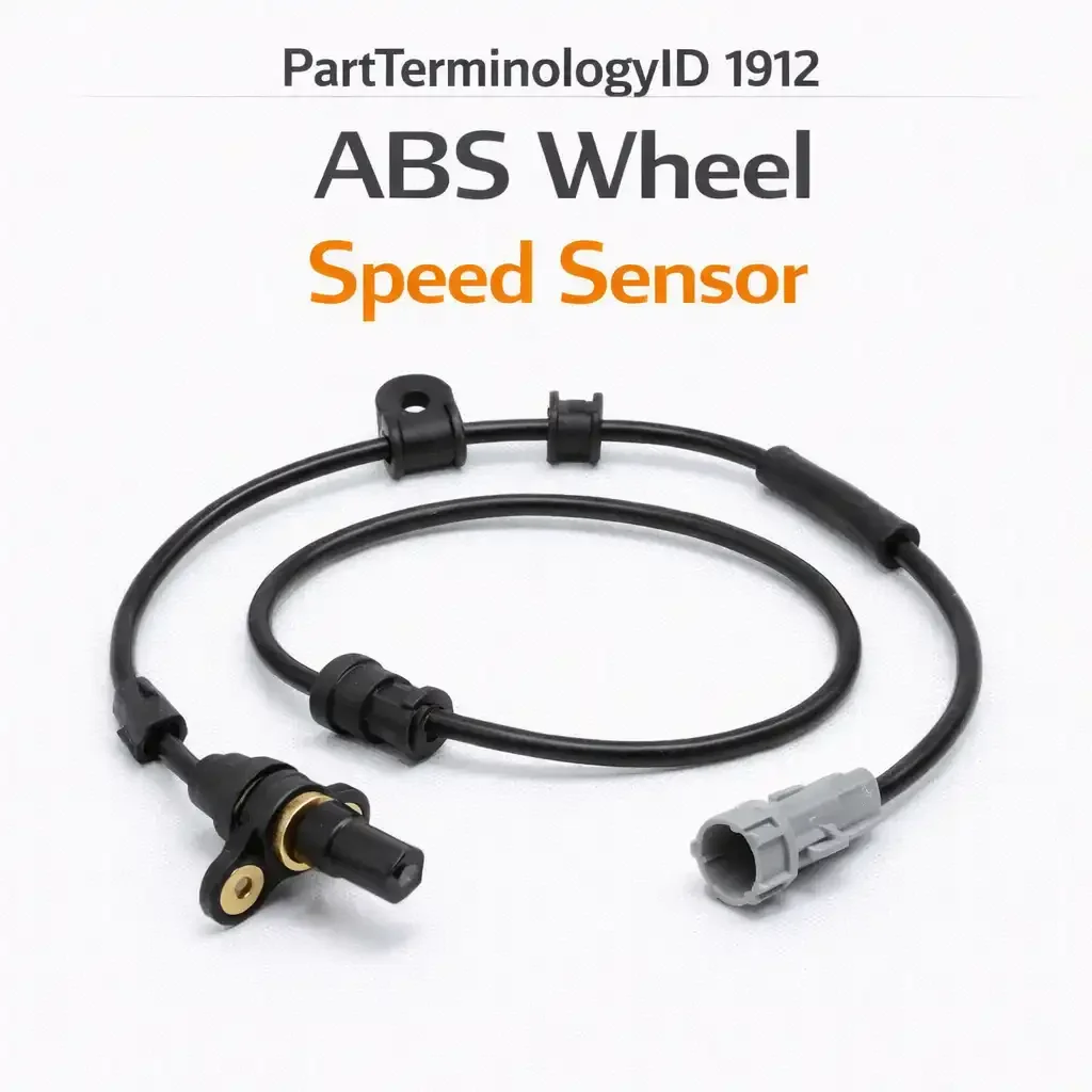
PartTerminologyID 1912, ABS Wheel Speed Sensor, is the electromagnetic or solid-state sensor mounted at each wheel that measures rotational speed and sends that data to the ABS control module (PartTerminologyID 1844). It is the primary input for anti-lock brakes. Without it, the ABS module has no way to determine whether a wheel is decelerating faster than the others, and the entire anti-lock function is disabled.
But the ABS wheel speed sensor has not been "just an ABS sensor" for over two decades. On any modern vehicle, the wheel speed data from these four sensors feeds not only the ABS, but also the traction control system, the electronic stability control system, the electronic brake force distribution system, the hill-start assist, the adaptive cruise control, the blind-spot monitoring radar calibration, the speedometer (on many vehicles, wheel speed sensors have replaced the traditional transmission-mounted vehicle speed sensor), and in some cases the transmission shift logic and the tire pressure monitoring system.
When one wheel speed sensor fails, the ABS control module loses the ability to compare that wheel's speed to the other three. The ABS disables itself. The traction control disables itself. The stability control disables itself. The dashboard lights up. And the buyer goes looking for a replacement sensor, entering an aftermarket category where the part looks simple but the fitment variables are anything but.
Why This Part Generates Returns at Scale
Buyers order the wrong ABS wheel speed sensor because:
they do not verify sensor technology type (passive inductive vs. active magneto-resistive), and the two types are not interchangeable
they do not verify whether the sensor is a standalone unit or integrated into the wheel hub/bearing assembly
they do not verify the connector type, pin count, and wiring harness length
they assume all four sensors on the vehicle are the same (front and rear sensors are almost always different, and on some vehicles left and right differ)
they do not verify the tone ring (reluctor ring) compatibility (passive sensors read a toothed ring, active sensors read a magnetic encoder ring, and the two ring types are not interchangeable with the wrong sensor type)
they miss ABS system manufacturer splits (Bosch, Continental/Teves, Delphi, Kelsey-Hayes) that determine sensor specifications within the same vehicle
they do not verify the mounting style (bolt-on, press-fit into knuckle bore, clip-mounted)
they confuse the ABS wheel speed sensor with the transmission vehicle speed sensor (VSS), which is a different component on vehicles that still use one
they order a sensor for a non-ABS vehicle that does not have wheel speed sensors (older vehicles without ABS have no sensors at this location)
they miss production date splits where the sensor type or connector changed mid-year
Sellers get caught because ABS wheel speed sensor listings commonly provide nothing more than a year/make/model fitment, a position (front or rear), and a photo. The sensor technology type, connector pinout, wiring length, and tone ring compatibility are omitted. The buyer orders, the sensor arrives, and it either has the wrong connector, the wrong mounting style, the wrong signal output for the ABS module, or the wrong relationship to the tone ring on the wheel hub.
Status in New Databases
PIES/PCdb: PartTerminologyID 1912, ABS Wheel Speed Sensor
PIES 8.0 / PCdb 2.0: No change
Sensor Technology: The Split That Matters Most
Passive (inductive) wheel speed sensors
The original ABS sensor technology, used from the introduction of ABS in the 1970s through the early 2000s on most vehicles, and still found on some applications today.
How they work: A passive sensor is a simple electromagnetic device consisting of a coil of wire wound around a permanent magnet. The sensor is mounted with its tip positioned near a toothed metal tone ring (reluctor ring) that rotates with the wheel. As each tooth passes the sensor tip, it creates a small change in the magnetic field, which induces an alternating current (AC) voltage in the coil. The frequency of the AC signal is proportional to the wheel's rotational speed. Faster rotation means more teeth passing per second, which means a higher frequency signal.
Signal characteristics: The output is a variable-amplitude, variable-frequency AC sine wave. At low wheel speeds, the signal amplitude is very low (millivolts), which makes it difficult for the ABS module to read accurately. At walking speed and below, passive sensors may not generate a usable signal at all. This is why early ABS systems could not function at very low speeds.
Tone ring compatibility: Passive sensors require a ferromagnetic (steel) toothed tone ring with a specific tooth count and tooth profile. The air gap between the sensor tip and the tone ring teeth is critical (typically 0.5 to 1.5mm). If the air gap is too large, the signal amplitude drops below the ABS module's detection threshold. If the gap is too small, the sensor tip can contact the spinning tone ring and be destroyed.
Physical characteristics: Passive sensors are typically larger than active sensors. They have a cylindrical body with a flange or mounting ear, and the sensing tip protrudes from the end. The connector is usually a two-pin connector (signal and ground), and the wiring harness is integrated into the sensor body.
Identification: Passive sensors typically have two wires (two-pin connector). They have no power supply requirement because they generate their own signal from the magnetic field interaction.
Active (magneto-resistive or Hall-effect) wheel speed sensors
The current standard on all modern vehicles, phasing in across the industry from the late 1990s through the 2000s.
How they work: An active sensor contains a semiconductor element (Hall-effect or magneto-resistive) that detects changes in a magnetic field. Unlike a passive sensor, the active sensor requires an external power supply (provided by the ABS module through the wiring harness). The sensor reads a magnetic encoder ring (a multi-pole magnetized ring, not a toothed steel ring) that rotates with the wheel. The encoder ring has alternating north and south magnetic poles embedded in a rubber or plastic carrier.
Signal characteristics: The output is a digital square wave signal with consistent amplitude regardless of wheel speed. This is the critical advantage over passive sensors. An active sensor produces a clean, readable signal even at very low speeds (essentially down to zero), which enables modern ABS, traction control, and stability control to function during parking maneuvers, low-speed creeping in traffic, and hill starts.
Additionally, active sensors can detect the direction of wheel rotation (forward vs. backward), not just speed. This capability is essential for hill-start assist and some stability control algorithms that need to know if the vehicle is rolling backward.
Tone ring compatibility: Active sensors require a magnetic encoder ring, not a ferromagnetic toothed ring. The encoder ring has a specific number of pole pairs and a specific pole pitch (the spacing between alternating north and south poles). The sensor and encoder ring must be matched. An active sensor pointed at a toothed steel ring will not generate a usable signal. A passive sensor pointed at a magnetic encoder ring will generate a distorted signal that the ABS module cannot interpret.
Physical characteristics: Active sensors are typically smaller and more compact than passive sensors. They may be flat (wafer-style) rather than cylindrical, because the sensing element does not need to protrude into the air gap the same way a passive sensor's magnetic tip does. Some active sensors are integrated directly into the wheel hub or bearing assembly (the sensing element is built into the bearing seal).
Identification: Active sensors typically have three wires (power, signal, ground) in a three-pin connector, though some use a two-wire current-mode interface where the digital signal is encoded as current pulses on the power supply wire. The wire count alone is not always a reliable identifier; the connector shape and pinout are more definitive.
Why this split is the most important fitment variable
A passive sensor installed in place of an active sensor will not work. It has no power input, it cannot read a magnetic encoder ring, and it produces an analog signal when the ABS module expects a digital one. The module will set fault codes and disable ABS.
An active sensor installed in place of a passive sensor will not work correctly either. It needs a power supply that the passive sensor wiring does not provide (unless the harness was designed for active sensors), and it will try to read a toothed steel ring instead of a magnetic encoder, producing garbage data.
On vehicles built during the transition period (roughly 1998 to 2008), the same model may have shipped with passive sensors in early production and active sensors in later production, sometimes within the same model year. The production date split is the only way to determine which sensor type the vehicle uses.
For sellers, this means that sensor technology type (passive or active) must be a required listing attribute. A listing that says "ABS wheel speed sensor, 2003 to 2008 [vehicle], front left" without specifying passive or active is covering a year range that likely spans the transition. Half the buyers will receive the wrong sensor type.
Standalone Sensors vs. Integrated Hub/Bearing Sensors
Standalone (serviceable) sensors
On many vehicles, the ABS wheel speed sensor is a separate component that mounts to the steering knuckle, axle housing, or backing plate and can be removed and replaced independently. The sensor's tip is positioned near the tone ring on the wheel hub, axle shaft, or CV joint.
Standalone sensors are the traditional configuration and the one that PartTerminologyID 1912 most directly describes. They are the sensor that the buyer removes, replaces, and plugs in.
Integrated sensors (built into the hub/bearing assembly)
On many modern vehicles, the ABS wheel speed sensor is integrated into the wheel hub and bearing assembly. The sensing element is embedded in the bearing seal or pressed into the hub body. The tone ring is built into the bearing inner race or a ring on the CV joint.
When an integrated sensor fails, the entire hub/bearing assembly must be replaced. There is no separately serviceable sensor to order. A buyer who searches for "ABS wheel speed sensor" for a vehicle with an integrated sensor will find listings for the standalone type, order one, and discover that their vehicle has no mounting point for a standalone sensor because the sensor is inside the bearing.
Conversely, a buyer whose vehicle uses a standalone sensor may accidentally order a complete hub/bearing assembly (which includes the sensor) when they only need the sensor itself. The hub assembly costs five to ten times more than the sensor.
For sellers, the listing must clarify whether the product is a standalone sensor or a hub/bearing assembly with an integrated sensor. And the catalog must flag applications where no standalone sensor exists, to prevent listing a PartTerminologyID 1912 product for a vehicle that requires a hub assembly instead.
Position: Front vs. Rear, Left vs. Right
Front vs. rear
Front and rear ABS wheel speed sensors are almost never the same part. The mounting location, mounting style, wiring harness length, and connector type differ between front and rear positions. Front sensors mount to the steering knuckle and must route their wiring through the suspension travel zone without snagging on steering components. Rear sensors mount to the axle housing, rear knuckle, or backing plate and have a different routing path.
The sensor's electrical specifications may also differ front to rear if the front and rear tone rings have different tooth counts or pole pair counts (which can happen on vehicles with different front and rear hub designs).
Left vs. right
On many vehicles, the left and right sensors at the same axle position are the same part number (the sensor is symmetrical and the wiring harness length is the same on both sides). But on some vehicles, the left and right sensors differ. The wiring harness may be longer on one side to account for asymmetric harness routing. The connector position may differ. The mounting angle may be mirrored on vehicles with asymmetric knuckle designs.
A listing that says "front" without specifying "left" or "right" works for vehicles where both sides are the same. It fails for vehicles where they differ. The listing should state the position explicitly (front left, front right, rear left, rear right) or note "fits both left and right" when applicable.
The Tone Ring Relationship
The sensor and the tone ring are a matched pair. The sensor type (passive or active) must match the tone ring type (toothed steel or magnetic encoder). But beyond that basic match, there are additional fitment considerations.
Tooth count / pole pair count
The ABS module is calibrated for a specific number of pulses per wheel revolution. If the sensor reads a tone ring with a different tooth count or pole pair count than the ABS module expects, the calculated wheel speed will be wrong. The ABS module may not set a fault code (the signal looks valid), but the speed value will be incorrect, which can cause the ABS to activate prematurely, the speedometer to read incorrectly, or the stability control to miscalculate yaw rate.
Tone ring tooth count changes when the vehicle manufacturer changes the hub or bearing design, which can happen across model years or between front and rear axles. The sensor listing should reference the tone ring tooth count or pole pair count it is designed to read.
Tone ring condition
A damaged, cracked, or corroded tone ring will produce erratic signals regardless of sensor quality. On vehicles with a toothed steel ring, rust and debris can fill the gaps between teeth, reducing the signal amplitude. On vehicles with a magnetic encoder ring (usually bonded to the bearing seal), damage to the rubber carrier or demagnetization of the poles will produce signal errors.
This matters for sellers because a significant percentage of ABS sensor returns are not sensor failures. The sensor is working correctly, but the tone ring it is reading is damaged. The buyer replaces the sensor, the ABS light stays on, and the buyer returns the "defective" sensor. A listing note about tone ring inspection can reduce these returns.
Connector and Wiring Harness
Connector type
ABS sensor connectors vary by vehicle manufacturer, ABS system supplier, model year, and production date. The connector may be a two-pin (passive) or three-pin (active) configuration, and the connector housing shape, lock tab design, and terminal arrangement are specific to the application.
An aftermarket sensor with the correct mounting style, correct sensing technology, and correct wiring length but the wrong connector will not plug into the vehicle's harness. The buyer must either return the sensor or splice the wiring, which is not recommended on a safety-critical circuit.
Wiring harness length
The sensor wiring harness is integrated into the sensor body (it is not a separate harness). The length of this integrated harness determines where the connector reaches relative to the vehicle's ABS wiring harness. Too short, and the connector does not reach the vehicle's mating connector. Too long, and the excess wiring must be secured to prevent it from snagging on suspension components.
Wiring length varies by vehicle position (front vs. rear), side (left vs. right on some vehicles), and model year (harness routing may change with body revisions).
Shielded vs. unshielded wiring
Some ABS sensor wiring is shielded (wrapped in a braided or foil shield to protect the signal from electromagnetic interference). This is more common on passive sensors, where the low-amplitude AC signal is susceptible to noise from ignition systems, electric motors, and other electromagnetic sources. Active sensors with digital outputs are less sensitive to interference, but some applications still use shielded wiring.
If the OE sensor uses shielded wiring and the replacement uses unshielded wiring, the sensor may produce intermittent signal errors, particularly in vehicles with high electromagnetic noise environments (diesel engines with high-output alternators, vehicles with aftermarket electronics).
Mounting Style
Bolt-on
The sensor has a flange with a bolt hole and is secured to the steering knuckle or backing plate with a bolt. The sensor tip protrudes through a bore in the knuckle to reach the tone ring.
Press-fit
The sensor body is pressed into a precision bore in the steering knuckle. There is no bolt. The sensor is retained by friction fit, sometimes with a small retaining clip. Press-fit sensors can be difficult to remove due to corrosion in the bore, and the bore diameter is critical to both sensor retention and air gap.
Clip-mounted
Some sensors are held in place by a spring clip or snap ring rather than a bolt or press fit. The clip style and dimensions must match the mounting boss on the knuckle or backing plate.
The mounting style is determined by the vehicle's knuckle or backing plate design. A bolt-on sensor will not mount in a press-fit bore (it has no friction surface to retain it). A press-fit sensor in a bolt-on application will fall out (it has no flange for a bolt).
Diagnostic Returns: The Sensor That Works But Gets Blamed
A substantial percentage of ABS wheel speed sensor returns are diagnostic errors. The buyer replaces the sensor, the ABS light stays on, and the buyer returns the sensor as defective. In reality, the ABS fault was caused by:
Damaged tone ring: Cracked, corroded, or missing teeth/poles. The new sensor reads the damaged ring and produces the same error signal as the old sensor.
Wiring harness damage: A chafed, corroded, or broken wire between the sensor connector and the ABS module. The new sensor's signal never reaches the module.
ABS module fault: The module itself has failed (internal relay, driver circuit, or processor failure). No sensor replacement will fix a module problem.
Air gap out of specification: On passive sensor applications, the gap between the sensor tip and the tone ring is too large (worn bearing, loose sensor mount) or too small (debris between sensor and ring).
Corrosion in the connector: The sensor-to-harness connector has corroded terminals that create high resistance or intermittent contact. The new sensor plugs into the same corroded connector and inherits the same fault.
Sellers cannot prevent diagnostic errors, but they can reduce return-the-sensor behavior with listing language:
"Before replacing the ABS wheel speed sensor, verify that the tone ring is undamaged, the sensor wiring harness is intact from the sensor to the ABS module connector, and the sensor connector terminals are clean and corrosion-free. A new sensor will not correct faults caused by tone ring damage, wiring breaks, or connector corrosion."
Top Return Scenarios
Scenario 1: "Sensor has the wrong number of pins"
Passive sensor (2-pin) shipped for an active sensor (3-pin) application, or vice versa.
Prevention language: "Sensor type: [passive (inductive) / active (Hall-effect / magneto-resistive)]. Connector: [2-pin / 3-pin]. Verify your original sensor's connector pin count and type before ordering."
Scenario 2: "My sensor is built into the hub bearing"
Vehicle has an integrated sensor in the hub assembly. No standalone sensor mounting point exists.
Prevention language: "Standalone ABS wheel speed sensor. Mounts to [steering knuckle / axle housing / backing plate]. Not for vehicles with ABS sensor integrated into the wheel hub/bearing assembly. If your vehicle has no external sensor mounting point, the sensor is integrated into the hub bearing and requires hub assembly replacement."
Scenario 3: "Connector doesn't match my harness"
Connector shape, lock tab, or terminal arrangement does not match the vehicle's ABS wiring harness connector.
Prevention language: "Connector type: [description, pin count, color, shape]. Verify connector matches your vehicle's ABS harness. Production date splits may change connector type within the same model year."
Scenario 4: "Wire isn't long enough to reach the plug"
Wiring harness length does not reach the vehicle's ABS harness mating connector.
Prevention language: "Wiring harness length (sensor to connector): [X inches / X mm]. Position: [front left / front right / rear left / rear right]. Verify wiring length matches your vehicle's harness routing."
Scenario 5: "ABS light is still on after replacing the sensor"
Tone ring, wiring, or ABS module fault causing the same symptom.
Prevention language: "If the ABS warning light remains illuminated after sensor replacement, inspect the tone ring for damage or corrosion, check the wiring harness for breaks or chafing, and verify the connector terminals are clean. A new sensor will not correct faults in other ABS system components."
Scenario 6: "I got a front sensor but I need a rear"
Position mismatch.
Prevention language: "Position: [front left / front right / rear left / rear right]. Front and rear sensors are different parts. Left and right sensors [are the same / differ by wiring length]. Verify position before ordering."
Scenario 7: "Sensor doesn't fit in the knuckle bore"
Mounting style mismatch (bolt-on vs. press-fit) or press-fit diameter mismatch.
Prevention language: "Mounting type: [bolt-on, M6 bolt / press-fit, X mm body diameter / clip-mounted]. Verify mounting style matches your steering knuckle or axle housing."
What to Include in the Listing
Core essentials
PartTerminologyID: 1912
component: ABS Wheel Speed Sensor
sensor type: passive (inductive) or active (Hall-effect / magneto-resistive)
standalone or integrated into hub/bearing (if standalone, state explicitly)
condition: new
quantity: 1
Fitment essentials
year/make/model/submodel
position: front left, front right, rear left, rear right (or "front, fits left and right")
ABS system manufacturer (Bosch, Continental, Delphi, Kelsey-Hayes)
drivetrain type (FWD, RWD, AWD, 4WD) if sensor differs
production date split (if sensor type or connector changed mid-year)
hub/bearing type (serviceable standalone or integrated sensor)
Electrical essentials
connector pin count (2-pin or 3-pin)
connector type/shape description
wiring harness length (sensor body to connector end)
shielded or unshielded wiring
output signal type (AC analog for passive, digital square wave for active)
Dimensional and mechanical essentials
mounting type (bolt-on, press-fit, clip)
sensor body diameter (for press-fit applications)
bolt thread size (for bolt-on applications)
air gap specification (for passive sensors)
compatible tone ring tooth count or pole pair count
Image essentials
full sensor with wiring harness laid out showing total length
connector close-up showing pin count and housing shape
mounting end close-up showing bolt flange or press-fit body
sensor tip detail
scale reference or dimensional callouts
Catalog Checklist for ACES/PIES Teams
PartTerminologyID = 1912
require sensor technology type (passive or active) as a mandatory attribute
require position attribute (front left, front right, rear left, rear right)
require connector pin count and type
require wiring harness length
require mounting type (bolt-on, press-fit, clip)
enforce production date splits where sensor type or connector changed mid-year
flag applications where the sensor is integrated into the hub/bearing assembly (no standalone sensor exists)
flag applications where left and right sensors differ (different wiring length or connector)
differentiate from transmission vehicle speed sensor (VSS)
require tone ring compatibility note (tooth count or pole pair count)
flag vehicles where the ABS system manufacturer changed within the model year range
FAQ (Buyer Language)
How do I know if my sensor is passive or active?
Check the connector at the sensor. Passive sensors typically have a two-pin connector and no power supply wire. Active sensors typically have a three-pin connector (power, signal, ground), though some use a two-wire current-mode interface. If uncertain, check your vehicle's service manual or contact the vehicle manufacturer. You can also check the tone ring: a toothed steel ring indicates a passive system, and a smooth rubber ring with embedded magnets indicates an active system.
Can I test the sensor before replacing it?
Passive sensors can be tested with a multimeter. Measure resistance across the two pins (typically 800 to 2,000 ohms, depending on the sensor). Then spin the wheel by hand and measure AC voltage across the pins. You should see a small AC signal (millivolts to a few hundred millivolts) that increases with spin speed. Active sensors require an oscilloscope or a scan tool that can read live wheel speed data, because they need a power supply to function.
My ABS light came on after a wheel bearing replacement. Do I need a new sensor?
If your vehicle has an integrated sensor in the hub/bearing assembly, the sensor was replaced when the bearing was replaced. If the ABS light is on, check the connector (it may not be fully seated) and the wiring harness (it may have been damaged during bearing installation). If your vehicle has a standalone sensor, verify that the sensor was reinstalled correctly and that the air gap to the tone ring is within specification. The tone ring may also have been damaged during the bearing press operation.
Is the front sensor the same as the rear sensor?
Almost never. Front and rear sensors differ in mounting style, wiring length, connector type, and sometimes sensor technology. Always verify your exact position (front left, front right, rear left, rear right) when ordering.
My speedometer is wrong after replacing the sensor. What happened?
On vehicles that derive speedometer readings from wheel speed sensors, an incorrect sensor (wrong tooth count/pole pair compatibility) will produce a wheel speed value that the instrument cluster converts to an incorrect vehicle speed. Verify that the replacement sensor is compatible with your vehicle's tone ring tooth count or encoder pole pair count.
Can I use a passive sensor with an active tone ring (or vice versa)?
No. Passive sensors require a ferromagnetic toothed tone ring. Active sensors require a magnetic encoder ring. The two technologies are not cross-compatible. Using the wrong combination will produce either no signal or an unreadable signal, and the ABS module will set a fault code.
Cross-Sell Logic
ABS Wheel Speed Sensor Wiring Harness / Connector Pigtail (if the harness or connector is damaged)
Wheel Hub/Bearing Assembly (for vehicles with integrated sensors, or if the tone ring is damaged)
ABS Tone Ring (if sold separately and the tone ring is the root cause)
ABS Control Module (PartTerminologyID 1844, if the module is the fault source)
Brake Caliper Mounting Bolt Kit (sensors are often accessed during brake service)
Scan Tool / Code Reader (for diagnosing ABS fault codes)
Frame as "diagnose before replacing: verify sensor, tone ring, and wiring before ordering. When the sensor is confirmed as the fault, these related components are commonly inspected or replaced at the same time."
The Bigger Picture: Why Wheel Speed Sensor Data Quality Matters Beyond ABS
The wheel speed sensor is the most consequential sensor in the modern chassis electronics suite. Its data feeds every system that needs to know how fast each wheel is turning, whether a wheel is slipping, and in which direction the wheels are rotating.
On a modern vehicle, incorrect wheel speed data caused by a faulty sensor, a damaged tone ring, or a mismatched replacement sensor can cause:
ABS to activate prematurely or not at all
traction control to cut engine power when it should not
stability control to apply braking to the wrong wheel
electronic brake force distribution to miscalculate front/rear pressure ratio
adaptive cruise control to misread closing speed
hill-start assist to release the brakes too early or too late
the speedometer to read high or low
the odometer to accumulate mileage incorrectly
transmission shift points to be wrong (on vehicles where wheel speed informs shift logic)
tire pressure monitoring to report false warnings (on indirect TPMS systems that use wheel speed data to infer tire pressure)
This is why the ABS wheel speed sensor listing must be specific. This is not a part where "close enough" works. The wrong sensor type, the wrong tooth count compatibility, or the wrong connector will cascade errors across half the electronic systems in the vehicle. And the buyer will blame the sensor, return it, order another one, and repeat the cycle until someone gets the listing right.
Final Take for PartTerminologyID 1912
ABS Wheel Speed Sensor (PartTerminologyID 1912) is the most interconnected sensor in the chassis. Its data touches more systems than any other single input in the vehicle. And its fitment is defined by a technology split (passive vs. active) that occurred at different times on different vehicles, creating a transition zone where the same model year can require either type.
Five attributes prevent the majority of returns: sensor technology type (passive or active), position (specific corner, not just "front"), connector pin count and type, wiring harness length, and mounting style. Those five fields resolve the ambiguity that causes a buyer to receive a two-pin passive sensor when their vehicle needs a three-pin active sensor, or a front-left sensor with a 24-inch harness when the front-right requires a 32-inch harness.
State the technology. State the position. State the connector. State the wire length. State the mounting type. That is the return prevention stack for the sensor that every safety system on the vehicle depends on.